EP0291966A1 - Verfahren und Gerät zum Steuern eines Robotersystems - Google Patents
Verfahren und Gerät zum Steuern eines Robotersystems Download PDFInfo
- Publication number
- EP0291966A1 EP0291966A1 EP88107983A EP88107983A EP0291966A1 EP 0291966 A1 EP0291966 A1 EP 0291966A1 EP 88107983 A EP88107983 A EP 88107983A EP 88107983 A EP88107983 A EP 88107983A EP 0291966 A1 EP0291966 A1 EP 0291966A1
- Authority
- EP
- European Patent Office
- Prior art keywords
- module
- message
- name
- transmit
- accordance
- Prior art date
- Legal status (The legal status is an assumption and is not a legal conclusion. Google has not performed a legal analysis and makes no representation as to the accuracy of the status listed.)
- Granted
Links
Images
Classifications
-
- G—PHYSICS
- G05—CONTROLLING; REGULATING
- G05B—CONTROL OR REGULATING SYSTEMS IN GENERAL; FUNCTIONAL ELEMENTS OF SUCH SYSTEMS; MONITORING OR TESTING ARRANGEMENTS FOR SUCH SYSTEMS OR ELEMENTS
- G05B19/00—Program-control systems
- G05B19/02—Program-control systems electric
- G05B19/18—Numerical control [NC], i.e. automatically operating machines, in particular machine tools, e.g. in a manufacturing environment, so as to execute positioning, movement or co-ordinated operations by means of program data in numerical form
- G05B19/402—Numerical control [NC], i.e. automatically operating machines, in particular machine tools, e.g. in a manufacturing environment, so as to execute positioning, movement or co-ordinated operations by means of program data in numerical form characterised by control arrangements for positioning, e.g. centring a tool relative to a hole in the workpiece, additional detection means to correct position
-
- G—PHYSICS
- G05—CONTROLLING; REGULATING
- G05B—CONTROL OR REGULATING SYSTEMS IN GENERAL; FUNCTIONAL ELEMENTS OF SUCH SYSTEMS; MONITORING OR TESTING ARRANGEMENTS FOR SUCH SYSTEMS OR ELEMENTS
- G05B19/00—Program-control systems
- G05B19/02—Program-control systems electric
- G05B19/18—Numerical control [NC], i.e. automatically operating machines, in particular machine tools, e.g. in a manufacturing environment, so as to execute positioning, movement or co-ordinated operations by means of program data in numerical form
- G05B19/414—Structure of the control system, e.g. common controller or multiprocessor systems, interface to servo, programmable interface controller
-
- G—PHYSICS
- G05—CONTROLLING; REGULATING
- G05B—CONTROL OR REGULATING SYSTEMS IN GENERAL; FUNCTIONAL ELEMENTS OF SUCH SYSTEMS; MONITORING OR TESTING ARRANGEMENTS FOR SUCH SYSTEMS OR ELEMENTS
- G05B2219/00—Program-control systems
- G05B2219/10—Plc systems
- G05B2219/11—Plc I-O input output
- G05B2219/1114—Address by module name
-
- Y—GENERAL TAGGING OF NEW TECHNOLOGICAL DEVELOPMENTS; GENERAL TAGGING OF CROSS-SECTIONAL TECHNOLOGIES SPANNING OVER SEVERAL SECTIONS OF THE IPC; TECHNICAL SUBJECTS COVERED BY FORMER USPC CROSS-REFERENCE ART COLLECTIONS [XRACs] AND DIGESTS
- Y02—TECHNOLOGIES OR APPLICATIONS FOR MITIGATION OR ADAPTATION AGAINST CLIMATE CHANGE
- Y02P—CLIMATE CHANGE MITIGATION TECHNOLOGIES IN THE PRODUCTION OR PROCESSING OF GOODS
- Y02P90/00—Enabling technologies with a potential contribution to greenhouse gas [GHG] emissions mitigation
- Y02P90/02—Total factory control, e.g. smart factories, flexible manufacturing systems [FMS] or integrated manufacturing systems [IMS]
Definitions
- the present invention relates to a robot system having a central control unit for managing the entire operation of the robot system and a plurality of peripheral control modules for controlling the operations of the respective portions of the robot. More particularly, the present invention relates to a communication control method of transmitting operation information among program modules of the central control unit, among control modules, and between the program modules and the control modules; and an apparatus for realizing the method.
- control system it is divided into peripheral control modules for controlling the respective portions of the mechanism and signal processing and a central control unit for managing and controlling the entire operation.
- the peripheral equipment such as a sensor belongs to the robot controller and performs input/output of a simple signal in response to a communication instruction incorporated in the robot language.
- the robot system In the conventional robot system, no serious problems occur when the robot performs a comparatively simple operation.
- the robot system when it is a so-called multifunction system, it has a plurality of peripheral control modules for independently controlling the respective portions of the robot. It also includes in the central control unit a plurality of program modules, which can concurrently be performed to exchange instruction signals between any two of the control modules and the program modules.
- the following problems arise.
- Each peripheral control module and each program module of the central control unit must have a work program that can cope with any possible situations. As a result, when the operation of the robot system is changed, or when the operation sequence of each control module is changed, a new work program must be created.
- the central control unit and each program module When a certain operation is instructed to a robot section and completion of the instructed operation is waited, the central control unit and each program module must monitor a signal transmitted from the corresponding robot section in a program manner, and other program processes cannot be performed during this monitoring.
- each program processing module of the central control unit independently and parallelly processes the program, it cannot control a corresponding control module immediately based on the processing result if other processing modules use the communication line.
- the present invention has been made in view of the above situation and has as its object to provide a communication control method of a robot system wherein when the arrangement of control modules is changed, a communication control can be performed without changing the program of each program module, when a new function is added to the robot, the method can sufficiently cope with it, and the operation of the respective portions of the robot can appropriately reflect the processing state and a request of each module; and an apparatus for realizing the method.
- the robot system comprises a plurality of program modules each for independently performing required program processing in the central control unit, a robot mechanism, and a plurality of control modules for controlling associated portions of the robot mechanism.
- communication is performed among program modules, among the control modules, and between the program modules and the peripheral control modules.
- a communication module is provided for performing communication management.
- Each module includes a data base on the connection style for communication with other module, a status buffers and a queue buffer for the modules.
- the status buffer stores the current status information of the each module, and the queue buffer sequentially stores the names of source modules, each of which has sent a message to a destination module, and the message itself.
- the destination module name and the message are transmitted to the communication module.
- the communication module alternately monitors messages transmitted from modules within the system, and the state of the queue buffer.
- the destination module name and the message are read in accordance with a reception procedure of the source module described in the connection style data base.
- the source module name and the message are stored in the queue buffer of the destination module.
- the stored message is monitored and found in the queue buffer.
- the source module name and the message are transmitted to the destination module in accordance with the transfer procedure described in the connection style data base.
- the control method can cope with it by altering the communication transfer status data base of the communication module.
- the message arrival order to a specific module is maintained at the reception order of the communication module by the queue. Therefore, even when a new function is added to the robot, the control method can sufficiently cope with it, and the respective portions of the robot can appropriately reflect the program processing state and request of each module.
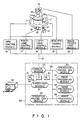
- Fig. 1 shows the arrangement of a robot system according to an embodiment of the present invention.
- the robot system has, e.g., 7-degree-of-freedom arms 11 and 11′, 6-degree-of-freedom dynamic amount measuring sensors 12 and 12′, and 4-degree-of-freedom hands 13 and 13′.
- Stereo camera 15 for obtaining visual information is provided above robot main body 10 through neck 14.
- Arm control module 16 controls arms 11 and 11′ in accordance with an arm control instruction.
- Right and left hand control modules 17 and 18 control hands 13 and 13′ in accordance with right and left hand control instructions, respectively.
- Head-eye control module 19 controls swing of neck 14 in accordance with input control instructions.
- Image proccesing hardware module 20 fetches image data in accordance with an input control instruction and transmits it.
- These peripheral control modules 16 to 20 respectively have a function to transmit and receive data.
- Central control unit 30 for managing the operation of the overall robot system is connected to terminal 40 and control modules 16 to 20 through external communication line 21.
- Terminal 40 displays the processing results of respective control modules 16 to 20 and the processing results of the respective program modules 31 to 37 of control unit 30. Necessary information is entered as required from terminal 40 by an operator.
- Central control unit 30 has supervisor module 31, work procedure generation modules 32 and 33, image processing modules 34 to 36, and communication module 37.
- Module 31 sends various control instructions to modules 16 to 20 and 32 and 33 to progress the overall operations.
- Work procedure generation modules 32 and 33 and image processing modules 34 to 36 serve as follows.
- Module 32 generates the parts assembly sequence from the structure of an assembly sample.
- Module 33 determines the operation sequences and operation amounts of the respective portions of the robot based on the parts assembly sequence.
- Module 34 fetches images of the assembly sample and estimates its structure.
- Module 35 detects a correction amount of a hand when a part is to be gripped.
- Module 36 detects relative positions of parts when they are to be assembled.
- Communication module 37 is connected to program modules 31 to 36 through internal communication system 38, and enables bidirectional communication among modules 31 to 36 in central control unit 30, among control modules 16 to 20, and between modules 31 to 36 and modules 16 to 20.
- Communication program module 37 is connected to transmission request list 41, queue buffer 39, and queue list 42.
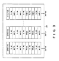
- Buffer 39 has queue areas 39-16, 39-17,..., and 39-36 corresponding to respective modules 16 to 36, as shown in Fig. 3. Each area sequentially stores a source module name (S.M.) and a message (MES.). The status of the module is also stored.
- S.M. source module name
- MES. message
- the status of the module is also stored.
- a transmission request is supplied, a number assigned to the module that has generated the transmission request is written in list 41.
- the number can be an identifier such as a module name.
- List 42 indicates whether a message is stored in each area of buffer 39 by means of 1 bit, i.e., 1 or 0.
- the number of messages stored in each area can be written in list 42 instead of 1 or 0 to indicate the presence of messages.
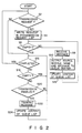
- step S2 module 37 monitors a transmission request from modules 16 to 20 and 31 to 36. If no transmission request is supplied, i.e., if NO in step S2, step S16 is executed. However, if YES in step S2, i.e., if a transmission request is supplied from e.g., module 16 to module 32 and from module 32 to module 17, numbers assigned to modules 16 and 32 are written in transmission request list 41 in step S4.
- step S6 it is checked whether transmission request list 41 is empty. If NO in step S6, step S8 is executed, and the numbers stored in list 41 are read out starting from the head of list 41.
- step S10 data is output from a module identified by its number, i.e., module 16 in this example.
- the data includes a destination module name and a message.
- a source module name is discriminated from the assigned number.
- the source module name and received message are written in area 39-32 of queue buffer 39 in accordance with the destination module name. In this case, when a message to be transmitted is already written in area 39-32, the source module name and message are written after it. Therefore, necessary data can be stored in buffer 39 while designating an appropriate destination module among modules 16 to 20 and 31 to 36.
- queue list 42 is updated to include a message corresponding to module 32 in step S12.
- step S6 is executed again. Since a transmission request supplied from module 32 is present in transmission request list 41, steps S8 to S12 are repeated in the same manner as described above.
- step S16 is executed, and it is checked from queue list 42 whether a message to be transmitted is present in queue buffer 39. If a message to be transmitted is present in buffer 39, it is output from buffer 39 to a corresponding module in a predetermined order. In this example, the order is module 16-20 and then module 31-36.
- step S18 it is first checked from queue list 41 whether a message destined to module 16 is present. If there is no such message, the same check is performed for module 17. If there is such a message, it is checked in step S20 whether destination module 17 is in an enabled state from the status written in area 39-17 of queue buffer 39. If NO in step S20, the flow returns to step S16.
- step S18 Assume that the processing for each destination module has progressed and that checking is to be performed for module 32 in step S18.
- a message destined to module 32 has been received in advance and written in queue buffer 39.
- NO is obtained in step S18 and it is checked in step S20 whether module 32 is in the enabled state. If YES in step S20, the message and the source module name that are read out from buffer 39 are transmitted to module 32 together with a destination module name in step S22. Then, queue list 42 is updated in step S24 and step S16 is executed. In this manner, a message is transmitted only once to each destination module.
- the enable/disable state of a corresponding one of modules 16 to 20 and 31 to 36 is updated by transmitting the changed module state to the status of queue buffer 39 through module 37.
- steps S16 to S24 are executed and a message is transmitted only once to each destination module.
- the transmission and reception sequences of each module can be kept unchanged. Since mutual communication among the respective modules is performed through module 37, the physical state of a destination module need not be considered, the entire arrangement can be simplified, and the flexibility of each module can be improved. Even when the system arrangement or the operating state is changed, only the program of module 37 need be modified and the information transmission path need not be modified. Modules 16 to 20 and 31 to 36 need not monitor the communication line, resulting in a simplified program.
- the same or different operation instructions can be supplied to a plurality of modules at once, and thus the parallel operations of the respective portions of the robot can be executed.
Landscapes
- Engineering & Computer Science (AREA)
- Human Computer Interaction (AREA)
- Manufacturing & Machinery (AREA)
- Physics & Mathematics (AREA)
- General Physics & Mathematics (AREA)
- Automation & Control Theory (AREA)
- Manipulator (AREA)
- Numerical Control (AREA)
- Computer And Data Communications (AREA)
- Selective Calling Equipment (AREA)
Applications Claiming Priority (2)
| Application Number | Priority Date | Filing Date | Title |
|---|---|---|---|
| JP62124604A JPS63289607A (ja) | 1987-05-21 | 1987-05-21 | 知能ロボットのモジュ−ル間通信制御方式 |
| JP124604/87 | 1987-05-21 |
Publications (2)
| Publication Number | Publication Date |
|---|---|
| EP0291966A1 true EP0291966A1 (de) | 1988-11-23 |
| EP0291966B1 EP0291966B1 (de) | 1992-08-05 |
Family
ID=14889550
Family Applications (1)
| Application Number | Title | Priority Date | Filing Date |
|---|---|---|---|
| EP88107983A Expired - Lifetime EP0291966B1 (de) | 1987-05-21 | 1988-05-18 | Verfahren und Gerät zum Steuern eines Robotersystems |
Country Status (5)
| Country | Link |
|---|---|
| US (1) | US4942512A (de) |
| EP (1) | EP0291966B1 (de) |
| JP (1) | JPS63289607A (de) |
| KR (1) | KR910000872B1 (de) |
| DE (1) | DE3873411T2 (de) |
Cited By (3)
| Publication number | Priority date | Publication date | Assignee | Title |
|---|---|---|---|---|
| EP0372085A4 (en) * | 1988-05-10 | 1993-12-01 | Fanuc Ltd | Pmc apparatus |
| EP0400624B1 (de) * | 1989-05-31 | 1994-10-26 | Kabushiki Kaisha Toshiba | Verteilersteuergerät |
| EP0399032B1 (de) * | 1988-12-09 | 1995-07-05 | SCHONLAU, William J. | Baukastenrobotersystem |
Families Citing this family (56)
| Publication number | Priority date | Publication date | Assignee | Title |
|---|---|---|---|---|
| FR2624633B1 (fr) * | 1987-12-14 | 1992-09-11 | Sgs Thomson Microelectronics | Systeme de programmation d'un robot |
| US5300869A (en) * | 1992-07-30 | 1994-04-05 | Iowa State University Research Foundation, Inc. | Nonholonomic camera space manipulation |
| US6925357B2 (en) * | 2002-07-25 | 2005-08-02 | Intouch Health, Inc. | Medical tele-robotic system |
| US20040162637A1 (en) * | 2002-07-25 | 2004-08-19 | Yulun Wang | Medical tele-robotic system with a master remote station with an arbitrator |
| SE0301910L (sv) * | 2003-06-26 | 2004-12-27 | Abb Ab | Datorstyrd arbetsplats med robotar |
| US7813836B2 (en) | 2003-12-09 | 2010-10-12 | Intouch Technologies, Inc. | Protocol for a remotely controlled videoconferencing robot |
| US20050204438A1 (en) | 2004-02-26 | 2005-09-15 | Yulun Wang | Graphical interface for a remote presence system |
| US8077963B2 (en) | 2004-07-13 | 2011-12-13 | Yulun Wang | Mobile robot with a head-based movement mapping scheme |
| US8000837B2 (en) | 2004-10-05 | 2011-08-16 | J&L Group International, Llc | Programmable load forming system, components thereof, and methods of use |
| US9198728B2 (en) | 2005-09-30 | 2015-12-01 | Intouch Technologies, Inc. | Multi-camera mobile teleconferencing platform |
| US8849679B2 (en) | 2006-06-15 | 2014-09-30 | Intouch Technologies, Inc. | Remote controlled robot system that provides medical images |
| US20070291128A1 (en) * | 2006-06-15 | 2007-12-20 | Yulun Wang | Mobile teleconferencing system that projects an image provided by a mobile robot |
| US9160783B2 (en) | 2007-05-09 | 2015-10-13 | Intouch Technologies, Inc. | Robot system that operates through a network firewall |
| JP5098456B2 (ja) * | 2007-06-15 | 2012-12-12 | 村田機械株式会社 | プロセス状態監視装置 |
| US10875182B2 (en) | 2008-03-20 | 2020-12-29 | Teladoc Health, Inc. | Remote presence system mounted to operating room hardware |
| US8179418B2 (en) | 2008-04-14 | 2012-05-15 | Intouch Technologies, Inc. | Robotic based health care system |
| US8170241B2 (en) | 2008-04-17 | 2012-05-01 | Intouch Technologies, Inc. | Mobile tele-presence system with a microphone system |
| US9193065B2 (en) | 2008-07-10 | 2015-11-24 | Intouch Technologies, Inc. | Docking system for a tele-presence robot |
| US9842192B2 (en) | 2008-07-11 | 2017-12-12 | Intouch Technologies, Inc. | Tele-presence robot system with multi-cast features |
| JP4577422B2 (ja) * | 2008-07-14 | 2010-11-10 | ソニー株式会社 | 情報処理システム及び情報処理方法、ロボットの制御システム及び制御方法、並びコンピュータ・プログラム |
| US8340819B2 (en) | 2008-09-18 | 2012-12-25 | Intouch Technologies, Inc. | Mobile videoconferencing robot system with network adaptive driving |
| US8996165B2 (en) | 2008-10-21 | 2015-03-31 | Intouch Technologies, Inc. | Telepresence robot with a camera boom |
| US8463435B2 (en) | 2008-11-25 | 2013-06-11 | Intouch Technologies, Inc. | Server connectivity control for tele-presence robot |
| US9138891B2 (en) | 2008-11-25 | 2015-09-22 | Intouch Technologies, Inc. | Server connectivity control for tele-presence robot |
| US8849680B2 (en) * | 2009-01-29 | 2014-09-30 | Intouch Technologies, Inc. | Documentation through a remote presence robot |
| US8897920B2 (en) | 2009-04-17 | 2014-11-25 | Intouch Technologies, Inc. | Tele-presence robot system with software modularity, projector and laser pointer |
| US8384755B2 (en) | 2009-08-26 | 2013-02-26 | Intouch Technologies, Inc. | Portable remote presence robot |
| US11399153B2 (en) * | 2009-08-26 | 2022-07-26 | Teladoc Health, Inc. | Portable telepresence apparatus |
| US11154981B2 (en) | 2010-02-04 | 2021-10-26 | Teladoc Health, Inc. | Robot user interface for telepresence robot system |
| US8670017B2 (en) | 2010-03-04 | 2014-03-11 | Intouch Technologies, Inc. | Remote presence system including a cart that supports a robot face and an overhead camera |
| US10343283B2 (en) | 2010-05-24 | 2019-07-09 | Intouch Technologies, Inc. | Telepresence robot system that can be accessed by a cellular phone |
| US10808882B2 (en) | 2010-05-26 | 2020-10-20 | Intouch Technologies, Inc. | Tele-robotic system with a robot face placed on a chair |
| US9264664B2 (en) | 2010-12-03 | 2016-02-16 | Intouch Technologies, Inc. | Systems and methods for dynamic bandwidth allocation |
| US12093036B2 (en) | 2011-01-21 | 2024-09-17 | Teladoc Health, Inc. | Telerobotic system with a dual application screen presentation |
| US9323250B2 (en) | 2011-01-28 | 2016-04-26 | Intouch Technologies, Inc. | Time-dependent navigation of telepresence robots |
| JP5905031B2 (ja) | 2011-01-28 | 2016-04-20 | インタッチ テクノロジーズ インコーポレイテッド | モバイルテレプレゼンスロボットとのインタフェーシング |
| US11482326B2 (en) | 2011-02-16 | 2022-10-25 | Teladog Health, Inc. | Systems and methods for network-based counseling |
| US10769739B2 (en) | 2011-04-25 | 2020-09-08 | Intouch Technologies, Inc. | Systems and methods for management of information among medical providers and facilities |
| US20140139616A1 (en) | 2012-01-27 | 2014-05-22 | Intouch Technologies, Inc. | Enhanced Diagnostics for a Telepresence Robot |
| US9098611B2 (en) | 2012-11-26 | 2015-08-04 | Intouch Technologies, Inc. | Enhanced video interaction for a user interface of a telepresence network |
| US8836751B2 (en) | 2011-11-08 | 2014-09-16 | Intouch Technologies, Inc. | Tele-presence system with a user interface that displays different communication links |
| US9251313B2 (en) | 2012-04-11 | 2016-02-02 | Intouch Technologies, Inc. | Systems and methods for visualizing and managing telepresence devices in healthcare networks |
| US8902278B2 (en) | 2012-04-11 | 2014-12-02 | Intouch Technologies, Inc. | Systems and methods for visualizing and managing telepresence devices in healthcare networks |
| US8726255B2 (en) | 2012-05-01 | 2014-05-13 | Concurix Corporation | Recompiling with generic to specific replacement |
| US8650538B2 (en) | 2012-05-01 | 2014-02-11 | Concurix Corporation | Meta garbage collection for functional code |
| US9361021B2 (en) | 2012-05-22 | 2016-06-07 | Irobot Corporation | Graphical user interfaces including touchpad driving interfaces for telemedicine devices |
| WO2013176760A1 (en) | 2012-05-22 | 2013-11-28 | Intouch Technologies, Inc. | Graphical user interfaces including touchpad driving interfaces for telemedicine devices |
| US8793669B2 (en) | 2012-07-17 | 2014-07-29 | Concurix Corporation | Pattern extraction from executable code in message passing environments |
| US9575813B2 (en) | 2012-07-17 | 2017-02-21 | Microsoft Technology Licensing, Llc | Pattern matching process scheduler with upstream optimization |
| JP6046467B2 (ja) * | 2012-11-29 | 2016-12-14 | 株式会社ダイヘン | ロボットシステム |
| KR102235166B1 (ko) * | 2015-09-21 | 2021-04-02 | 주식회사 레인보우로보틱스 | 실시간 로봇 시스템, 로봇 시스템 제어 장치 및 로봇 시스템 제어 방법 |
| CN105488892B (zh) * | 2016-01-04 | 2018-03-30 | 杭州亚美利嘉科技有限公司 | 一种用于机器人排队管理的方法及服务器 |
| US11862302B2 (en) | 2017-04-24 | 2024-01-02 | Teladoc Health, Inc. | Automated transcription and documentation of tele-health encounters |
| US10483007B2 (en) | 2017-07-25 | 2019-11-19 | Intouch Technologies, Inc. | Modular telehealth cart with thermal imaging and touch screen user interface |
| US11636944B2 (en) | 2017-08-25 | 2023-04-25 | Teladoc Health, Inc. | Connectivity infrastructure for a telehealth platform |
| US10617299B2 (en) | 2018-04-27 | 2020-04-14 | Intouch Technologies, Inc. | Telehealth cart that supports a removable tablet with seamless audio/video switching |
Citations (5)
| Publication number | Priority date | Publication date | Assignee | Title |
|---|---|---|---|---|
| EP0022622A1 (de) * | 1979-06-19 | 1981-01-21 | Gould Inc. | Programmierbare Steuerung |
| WO1983001520A1 (en) * | 1981-10-26 | 1983-04-28 | Us Robots Inc | Robot arm controller with common bus memory |
| EP0090302A1 (de) * | 1982-03-30 | 1983-10-05 | Cincinnati Milacron Inc. | Programmierbares Steuergerät und Verfahren |
| EP0162670A2 (de) * | 1984-05-19 | 1985-11-27 | British Aerospace Public Limited Company | Industrielle Verarbeitungs- und Herstellungsverfahren |
| EP0201081A2 (de) * | 1985-05-10 | 1986-11-12 | Hitachi, Ltd. | Steuergerät |
Family Cites Families (7)
| Publication number | Priority date | Publication date | Assignee | Title |
|---|---|---|---|---|
| US4428043A (en) * | 1981-08-24 | 1984-01-24 | Burroughs Corporation | Data communications network |
| DE3236302A1 (de) * | 1982-09-30 | 1984-04-05 | Siemens AG, 1000 Berlin und 8000 München | Speicherprogrammierbare steuerung |
| US4607256A (en) * | 1983-10-07 | 1986-08-19 | Honeywell, Inc. | Plant management system |
| JPS60256875A (ja) * | 1984-06-01 | 1985-12-18 | Mitsubishi Electric Corp | 画像処理装置 |
| US4658351A (en) * | 1984-10-09 | 1987-04-14 | Wang Laboratories, Inc. | Task control means for a multi-tasking data processing system |
| JPS61117605A (ja) * | 1984-11-14 | 1986-06-05 | Hitachi Ltd | ロボツトの制御方法 |
| US4706120A (en) * | 1985-08-30 | 1987-11-10 | Texas Instruments Incorporated | Modular, vision system for automation of inspection and process control |
-
1987
- 1987-05-21 JP JP62124604A patent/JPS63289607A/ja active Pending
-
1988
- 1988-05-18 EP EP88107983A patent/EP0291966B1/de not_active Expired - Lifetime
- 1988-05-18 DE DE8888107983T patent/DE3873411T2/de not_active Expired - Fee Related
- 1988-05-19 US US07/196,063 patent/US4942512A/en not_active Expired - Fee Related
- 1988-05-21 KR KR1019880006068A patent/KR910000872B1/ko not_active Expired
Patent Citations (5)
| Publication number | Priority date | Publication date | Assignee | Title |
|---|---|---|---|---|
| EP0022622A1 (de) * | 1979-06-19 | 1981-01-21 | Gould Inc. | Programmierbare Steuerung |
| WO1983001520A1 (en) * | 1981-10-26 | 1983-04-28 | Us Robots Inc | Robot arm controller with common bus memory |
| EP0090302A1 (de) * | 1982-03-30 | 1983-10-05 | Cincinnati Milacron Inc. | Programmierbares Steuergerät und Verfahren |
| EP0162670A2 (de) * | 1984-05-19 | 1985-11-27 | British Aerospace Public Limited Company | Industrielle Verarbeitungs- und Herstellungsverfahren |
| EP0201081A2 (de) * | 1985-05-10 | 1986-11-12 | Hitachi, Ltd. | Steuergerät |
Cited By (3)
| Publication number | Priority date | Publication date | Assignee | Title |
|---|---|---|---|---|
| EP0372085A4 (en) * | 1988-05-10 | 1993-12-01 | Fanuc Ltd | Pmc apparatus |
| EP0399032B1 (de) * | 1988-12-09 | 1995-07-05 | SCHONLAU, William J. | Baukastenrobotersystem |
| EP0400624B1 (de) * | 1989-05-31 | 1994-10-26 | Kabushiki Kaisha Toshiba | Verteilersteuergerät |
Also Published As
| Publication number | Publication date |
|---|---|
| JPS63289607A (ja) | 1988-11-28 |
| DE3873411D1 (de) | 1992-09-10 |
| EP0291966B1 (de) | 1992-08-05 |
| DE3873411T2 (de) | 1993-02-25 |
| US4942512A (en) | 1990-07-17 |
| KR910000872B1 (ko) | 1991-02-11 |
| KR880014430A (ko) | 1988-12-23 |
Similar Documents
| Publication | Publication Date | Title |
|---|---|---|
| US4942512A (en) | Control method of robot system and apparatus for realizing the same | |
| US5928351A (en) | Parallel computer system with communications network for selecting computer nodes for barrier synchronization | |
| US4888726A (en) | Distributed processing in a cluster of industrial controls linked by a communications network | |
| JPH114279A (ja) | 先進的システム間送信方法および機構 | |
| US4628442A (en) | Centralized peripheral interface with a numerical control unit | |
| JPH0451662A (ja) | ファクシミリ制御方式 | |
| JP3566057B2 (ja) | 監視制御装置 | |
| JPS5936287B2 (ja) | デ−タ転送方式 | |
| KR0182707B1 (ko) | 교환기에 있어서 프로세서간통신 메세지에 대한 모니터장치 및 방법 | |
| KR950009570B1 (ko) | 데이타 링크 시스템 | |
| JPH01232852A (ja) | 通信制御システム | |
| JP2658129B2 (ja) | データ伝送装置 | |
| JP3217086B2 (ja) | 二重化システムにおける待機系制御装置とメッセージ装置間のメッセージ交信方式 | |
| JPH0793275A (ja) | 空き装置選択方法 | |
| EP0187420A1 (de) | Nachrichtenverarbeitungs- und -übertragungssystem und Netzwerk dafür | |
| JPH0326046A (ja) | 交換機端末の入出力制御方式 | |
| JPH08293919A (ja) | 集中保守管理システムの過負荷試験装置 | |
| JPH01171395A (ja) | 遠方監視制御装置の伝送異常処理方式 | |
| JPH08263457A (ja) | 代行処理システム | |
| JPH0447305A (ja) | セルコントローラ | |
| JPS58182749A (ja) | 分散形制御装置におけるデ−タ通信方式 | |
| JPS61165173A (ja) | システム間の状態情報管理方式 | |
| JPS62169544A (ja) | ル−プネツトワ−クにおけるマルチ接続方法 | |
| JPS63238741A (ja) | 伝送制御手順階層処理方式 | |
| JPH04293105A (ja) | 数値制御装置のリモート診断装置 |
Legal Events
| Date | Code | Title | Description |
|---|---|---|---|
| PUAI | Public reference made under article 153(3) epc to a published international application that has entered the european phase |
Free format text: ORIGINAL CODE: 0009012 |
|
| 17P | Request for examination filed |
Effective date: 19880615 |
|
| AK | Designated contracting states |
Kind code of ref document: A1 Designated state(s): DE GB IT NL |
|
| 17Q | First examination report despatched |
Effective date: 19900525 |
|
| GRAA | (expected) grant |
Free format text: ORIGINAL CODE: 0009210 |
|
| AK | Designated contracting states |
Kind code of ref document: B1 Designated state(s): DE GB IT NL |
|
| ITF | It: translation for a ep patent filed | ||
| REF | Corresponds to: |
Ref document number: 3873411 Country of ref document: DE Date of ref document: 19920910 |
|
| ITTA | It: last paid annual fee | ||
| PLBE | No opposition filed within time limit |
Free format text: ORIGINAL CODE: 0009261 |
|
| STAA | Information on the status of an ep patent application or granted ep patent |
Free format text: STATUS: NO OPPOSITION FILED WITHIN TIME LIMIT |
|
| 26N | No opposition filed | ||
| PGFP | Annual fee paid to national office [announced via postgrant information from national office to epo] |
Ref country code: GB Payment date: 19940511 Year of fee payment: 7 Ref country code: DE Payment date: 19940511 Year of fee payment: 7 |
|
| PGFP | Annual fee paid to national office [announced via postgrant information from national office to epo] |
Ref country code: NL Payment date: 19940531 Year of fee payment: 7 |
|
| PG25 | Lapsed in a contracting state [announced via postgrant information from national office to epo] |
Ref country code: GB Effective date: 19950518 |
|
| PG25 | Lapsed in a contracting state [announced via postgrant information from national office to epo] |
Ref country code: NL Effective date: 19951201 |
|
| GBPC | Gb: european patent ceased through non-payment of renewal fee |
Effective date: 19950518 |
|
| NLV4 | Nl: lapsed or anulled due to non-payment of the annual fee |
Effective date: 19951201 |
|
| PG25 | Lapsed in a contracting state [announced via postgrant information from national office to epo] |
Ref country code: DE Effective date: 19960201 |
|
| PG25 | Lapsed in a contracting state [announced via postgrant information from national office to epo] |
Ref country code: IT Free format text: LAPSE BECAUSE OF NON-PAYMENT OF DUE FEES;WARNING: LAPSES OF ITALIAN PATENTS WITH EFFECTIVE DATE BEFORE 2007 MAY HAVE OCCURRED AT ANY TIME BEFORE 2007. THE CORRECT EFFECTIVE DATE MAY BE DIFFERENT FROM THE ONE RECORDED. Effective date: 20050518 |