EP0295473A2 - Kühlmittelpumpe für einen Reaktor mit hydrostatischer Dichtungsanordnung mit hydraulischem Gleichgewicht - Google Patents
Kühlmittelpumpe für einen Reaktor mit hydrostatischer Dichtungsanordnung mit hydraulischem Gleichgewicht Download PDFInfo
- Publication number
- EP0295473A2 EP0295473A2 EP88108475A EP88108475A EP0295473A2 EP 0295473 A2 EP0295473 A2 EP 0295473A2 EP 88108475 A EP88108475 A EP 88108475A EP 88108475 A EP88108475 A EP 88108475A EP 0295473 A2 EP0295473 A2 EP 0295473A2
- Authority
- EP
- European Patent Office
- Prior art keywords
- seal ring
- sealing assembly
- pump
- pressure
- seal
- Prior art date
- Legal status (The legal status is an assumption and is not a legal conclusion. Google has not performed a legal analysis and makes no representation as to the accuracy of the status listed.)
- Granted
Links
Images


Classifications
-
- F—MECHANICAL ENGINEERING; LIGHTING; HEATING; WEAPONS; BLASTING
- F16—ENGINEERING ELEMENTS AND UNITS; GENERAL MEASURES FOR PRODUCING AND MAINTAINING EFFECTIVE FUNCTIONING OF MACHINES OR INSTALLATIONS; THERMAL INSULATION IN GENERAL
- F16J—PISTONS; CYLINDERS; SEALINGS
- F16J15/00—Sealings
- F16J15/16—Sealings between relatively-moving surfaces
- F16J15/34—Sealings between relatively-moving surfaces with slip-ring pressed against a more or less radial face on one member
- F16J15/3436—Pressing means
- F16J15/346—Pressing means the pressing force varying during operation
Definitions
- the present invention relates to a hydrostatic sealing assembly with improved hydraulic balance useful in sealing a shaft of a reactor coolant pump used in a nuclear power plant.
- a reactor coolant system In pressurized water nuclear power plants, a reactor coolant system is used to transport heat from the reactor core to steam generators for the production of steam. The steam is then used to drive a turbine generator.
- the reactor coolant system includes a plurality of separate cooling loops, each connected to the reactor core and containing a steam generator and a reactor coolant pump.
- the reactor coolant pump typically is a vertical, single stage, centrifugal pump designed to move large volumes of reactor coolant at high temperatures and pressures, for example 288°C (550°F) and 17.2 MPa (2500 psi).
- the pump basically includes three general sections from bottom to top -- hydraulic, shaft seal and motor sections.
- the lower hydraulic section includes an impeller mounted on the lower end of a pump shaft which is operable within the pump casing to pump reactor coolant about the respective loop.
- the upper motor section includes a motor which is coupled to drive the pump shaft.
- the middle shaft seal section includes three tandem sealing assemblies -- lower primary, middle secondary and upper tertiary sealing assemblies.
- the sealing assemblies are located concentric to, and near the top end of, the pump shaft and their combined purpose is to provide for zero reactor coolant leakage along the pump shaft to the containment atmosphere during normal operating condition.
- Representative examples of pump shaft sealing assemblies known in the prior art are the ones disclosed in U.S. Patents to MacCrum (3,522,948), Singleton (3,529,838), Villasor (3,632,117), Andrews et al. (3,720,222) and Boes (4,275,891) and in the first three patent applications cross-referenced above, all of which are assigned to the same assignee as the present invention.
- the lower primary sealing assembly is the main seal of the pump. It is typically a hydrostatic, radially tapered "film-riding", controlled leakage seal whose primary components are an annular runner which rotates with the pump shaft and a non-rotating seal ring which is attached to the housing of the lower sealing assembly.
- hydrostatic seals are the one disclosed hereinafter and the ones disclosed in the MacCrum, Singleton, Villasor and Andrews et al. patents.
- the pump shaft seals constitute the main problem area for the reactor coolant pumps and significantly contribute to the utilization factor in nuclear power plants.
- the seals must be capable of breaking down the high system pressure (about 17.2 MPa (2500 psi)) safely.
- the tandem arrangement of three seals is used to break down the pressure
- the lower main seal absorbs most of the pressure drop (approximately 15.5 MPa (2250 psi)).
- the lower seal Being a hydrostatic "film-riding" seal, the lower seal is designed to "lift off” (separate) at low system pressures without pump rotation.
- the lifting force is produced by a hydrostatic pressure force present in the gap between the stationary seal ring and the rotating runner.
- a closing or seating force which must balance the lifting force, is produced by the system pressure acting on surfaces opposite the film surfaces of the seal ring and runner.
- One of the potential problems associated with the lower seal stems from the preference to use a very pure grade of aluminum oxide as the faceplate material for the seal ring and runner.
- Use of such material is advantageous since it is harder than crud particles (usually iron oxide) which are small enough to enter the gap between the faces of the seal ring and runner, but large enough to lodge part way through the gap.
- crud particles usually iron oxide
- a major disadvantage of aluminum oxide is that it is basically incompatible in rubbing against itself. If the seal faces momentarily contact while in motion, then usually some damage can be expected. If the rub is heavy enough, the faces are very seriously damaged and in some cases the thermal shock can lead to cracking and breakup of the structure.
- a minimum differential pressure of about 1.4 MPa (200 psi) must be maintained to establish a stable film between the faces and prevent rubbing when starting the pump.
- a minimum leakrate of about 0.75 liter per minute (0.2 gpm) is required for cooling and, most importantly, as a means of determining that an adequate film thickness exists prior to starting.
- the seal is most vulnerable at plant startup since the available differential pressure is low and crud may be present. Once the film is established, however, there is practically no seal face wear and the seal has a very long life expectancy.
- the present invention resides in a pump having a shaft and a housing, said housing containing pressurized fluid variable in supply pressure between pump startup pump and pump operation, a hydrostatic sealing assembly for sealably and rotatably mounting said shaft within said housing, said sealing assembly characterized by: (a) an annular runner circumscribing and mounted around said shaft for rotation therewith; (b) an annular seal ring circumscribing and mounted within said housing in non-rotational relationship thereto but for translatory movement along said shaft; (c) said runner and seal ring having surfaces facing one another and between which the pressurized fluid within said housing creates a flowing film of low pressure fluid which prevents said facing surfaces of said respective runner and seal ring from coming into contact with one another so long as a predetermined minimum leakrate is maintained therebetween; (d) means defining first and second surfaces on said seal ring facing in a direction opposite to that of its facing surface and in sealingly isolated relationship from one another, said first surface being in communication with
- the first surface of the seal ring defines a substantially larger area than the second surface thereof.
- the means defining the first and second surfaces on the seal ring includes first and second spaced apart annular seal means disposed along the seal ring between the seal ring and the shaft, and defining first and second chambers disposed contiguous with the first and second isolated surfaces on the seal ring.
- the first annular seal means sealingly isolates the first chamber from the second chamber and in communication with the pressurized fluid at the supply pressure.
- the second annular seal means sealingly isolates the second chamber from the first chamber and the facing surfaces of the runner and the seal ring.
- control means disposed in the seal ring includes a flow control device movably disposed in the seal ring and being operable between first and second oppositely displaced positions, and a plurality of passages formed in the seal ring.
- a first of the passages communicates the device with the seal ring second surface
- a second of the passages communicates the device with a side of the seal ring at the supply pressure
- a third of the passages communicates the device with an opposite side of the seal ring at the lower pressure.
- the flow control device When the flow control device is displaced at its first position, communication is opened between the low pressure and the seal ring second surface, whereas when the flow control device is displaced at its second position, communication is opened between the supply (higher) pressure and the seal ring second surface.
- the flow control device is biased to automatically move to its first position when the supply pressure of the pressurized fluid is below a preset pressure at pump startup, and is movable to its second position when the supply pressure of the pressurized fluid rises above the preset pressure at pump operation.
- the flow control device can be a spool or poppet valve.
- the cooling loop 10 includes a steam generator 12 and a reactor coolant pump 14 serially connected in a closed coolant flow circuit with a nuclear reactor core 16.
- the steam generator 12 includes primary tubes 18 communicating with inlet and outlet plenums 20, 22 of the generator.
- the inlet plenum 20 of the steam generator 12 is connected in flow communication with the outlet of the reactor core 16 for receiving hot coolant therefrom along flow path 24 of the closed flow circuit.
- the outlet plenum 22 of the steam generator 12 is connected in flow communication with an inlet suction side of the reactor coolant pump 14 along flow path 26 of the closed flow circuit.
- the outlet pressure side of the reactor coolant pump 14 is connected in flow communication with the inlet of the reactor core 16 for feeding cold coolant thereto along flow path 28 of the closed flow circuit.
- the coolant pump 14 pumps the coolant under high pressure about the closed flow circuit.
- hot coolant emanating from the reactor core 16 is conducted to the inlet plenum 20 of the steam generator 12 and to the primary tubes 18 in communication therewith. While in the primary tubes 18, the hot coolant flows in heat exchange relationship with cool feedwater supplied to the steam generator 12 via conventional means (not shown).
- the feedwater is heated and portions thereof changed to steam for use in driving a turbine generator (not shown).
- the coolant whose temperature has been reduced by the heat exchange, is then recirculated to the reactor core 16 via the coolant pump 14.
- the reactor coolant pump 14 must be capable of moving large volumes of reactor coolant at high temperatures and pressures about the closed flow circuit. Although, the temperature of the coolant flowing from the steam generator 12 to the pump 14 after heat exchange has been cooled substantially below the temperature of the coolant flowing to the steam generator 12 from the reactor core 16 before heat exchange, its temperature is still relatively high, being typically about 288°C (550°F). The coolant pressure produced by the pump is typically about 17.2 MPa (2500 psi).
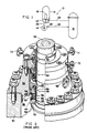
- the prior art reactor coolant pump 14 generally includes a pump housing 30 which terminates at one end in a seal housing 32.
- the pump 14 also includes a pump shaft 34 extending centrally of the housing 30 and being sealingly and rotatably mounted within the seal housing 32.
- the bottom portion of the pump shaft 34 is connected to an impeller, while a top portion thereof is connected to a high-horsepower, induction-type electric motor.
- the impeller within the interior 36 of the housing 30 circulates the coolant flowing through the pump housing 30 at pressures from ambient to approximately 17.2 MPa (2500 psi).
- This pressurized coolant applies an upwardly directed, hydrostatic load upon the shaft 34 since the outer portion of the seal housing 32 is surrounded by the ambient atmosphere.
- tandemly-arranged lower primary, middle secondary and upper tertiary sealing assemblies 38, 40, 42 are provided in the positions illustrated in Figs. 2 and 3 about the pump shaft 34 and within the pump housing 30.
- the lower primary sealing assembly 38 which performs most of the pressure sealing (approximately 15.5 MPa (2250 psi)) is of the non-contacting hydrostatic type, whereas the middle secondary and upper tertiary sealing assemblies 40, 42 are of the contacting, mechanical type.
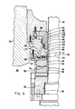
- the lower hydrostatic primary sealing assembly 38 of the prior art pump 14 generally includes an annular runner 44 which is mounted to the pump shaft 34 for rotation therewith and an annular seal ring 46 which is stationarily mounted within the seal housing 32.
- the runner 44 includes an annular runner faceplate 48 mounted by a hydrostatic clamp ring 50 to an annular runner support member 52 which, in turn, is keyed to the pump shaft 34 by anti-rotation pins 54.
- the seal ring 46 includes an annular ring faceplate 56 mounted by a hydrostatic clamp ring 58 to an annular ring support member 60 which, in turn, is keyed to the seal housing 32 by anti-rotation pin 62 so as to prevent rotational movement of the seal ring 46 relative to the seal housing 32 but allow translatory movement of the seal ring 46 along pump shaft 34 toward and away from the runner 44.
- Facing (or top and bottom) surfaces 64, 66 of the respective runner and ring faceplates 48, 56 are biased toward one another as a result of the coolant pressure load on the pump shaft 34.
- the surfaces 64, 66 normally do not frictionally engage one another, since the surface 66 of the seal ring faceplate 56 is tapered at a shallow angle with respect to the substantially flat and horizontal surface 64 on the runner faceplate 48.
- Such tapering provides a flowing film of coolant fluid between the surfaces 64, 66 which, in turn, allows the runner 44 and seal ring 46 to rotate relative to one another in a "film-riding" mode.
- the seal housing 32 includes a primary leakoff port 68, whereas leakoff port 70 accommodates coolant fluid leakoff from the secondary sealing assembly 40 and leakoff port 71 accommodates coolant fluid leakoff from the tertiary sealing assembly 42.
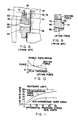
- the facing surfaces 64, 66 of the respective runner 44 and seal ring 46 of the primary sealing assembly 38 are designed to "lift off” or separate at low system pressure without pump shaft rotation.
- the lifting force is produced by the hydrostatic pressure force between the runner 44 and seal ring 46.
- an opposing seating force which must balance the lifting force, is produced by the system pressure acting on a pair of adjacent outer and inner peripheral upwardly-facing surfaces 72, 74 of the seal ring 46 located on an opposite side thereof from its downwardly-facing surface 66.
- the lifting force graphically depicted in Fig. 10, varies inversely with film thickness between the facing surfaces 64, 66 of the runner 44 and seal ring 46. So where the ring 46 is tapered with a convergent flow path, the lifting force will decrease as the film thickness increases.
- the O-ring 76 allows the seal ring 46 to vertically ride on a cylindrical wear sleeve 80 which forms part of the seal housing 32 of the coolant pump 14 in order for the seal ring to adjust to pump shaft motion and pressure changes.
- the seal provided by the O-ring 76 not only prevents leakage, but also serves to determine the magnitude of the seating force.
- the O-ring 76 defines an upper chamber 81 which communicates with system pressure fluid and a lower chamber 83 which communicates with low pressure fluid emanating from the flow of fluid film into the gap between the facing surfaces 64, 66.
- the inner diameter of the upper portion of seal ring 46 determines the position of transition from high system pressure to low back pressure and thus determines the magnitude of the pressure component of the seating force in Fig. 10.
- the seating force is quite sizable. At full system pressure, it is nearly equal to 445 kN (100,000 lbs).
- the material of the faceplates 48, 56 in Fig. 4 is preferably aluminum oxide.
- a minimum differential pressure approximately 1.4 MPa (200 psi)
- the seal provided between the faceplates is most vulnerable at startup since the available differential pressure is low and the sealing film must be established to prevent rubbing of the facing surfaces 64, 66.
- the resulting leakage is an order of magnitude less than at full pressure.
- the required minimum leakage to startup of about 0.75 liter per minute (0.2 gpm) can, in fact, be too small to accurately measure with the instruments that are presently used in reactor power plants.
- low leakage can be an indication of possible crud blockage at the facing surfaces 64, 66 or failure of the surfaces to separate, operators are reluctant to start the pump to avoid damaging the facing surfaces of the primary sealing assembly 38. In a high percentage of cases, the low leakrates are simply due to unreliable instrumentation.
- To correct the problem or confirm the lack of a problem operators conduct a number of involved system checks. The effort is time consuming and a continuing nuisance in an operation where the pumps represent a small part of the startup logistics.
- seal designers can open up the seal faceplate convergence angle (taper).
- this would result in high leakrates across the entire pressure range.
- the primary disadvantage with this technique is at high system pressure where the resulting leakrates approach and may exceed shutdown limits.
- the increased convergence angle (taper) is, in fact, opposite to what seal designers would prefer to introduce were it not for the low pressure leakage requirement.
- a reduction in the convergence angle (taper) would reduce the high pressure leakrates and provide significantly more margin to shutdown limits, but this would introduce leakrates below the minimum acceptable at low system pressures.
- the solution to the problem is a seal which maintains a constant leakage over the pressure range.
- either the convergence angle (taper) or the seating force would have to change in a controlled manner over the entire system pressure range. Varying either one of these parameters in a controlled fashion becomes a very difficult and complex challenge.
- a more practical and relatively simple alternative is proposed by the present invention.
- Figs. 5 and 12 there is shown the modified primary sealing assembly of the present invention, being generally designated by the numeral 82. Only the parts of the modified primary sealing assembly 82 which are different from the prior art primary sealing assembly 38, and thus relate to the modifications underlying the present invention, will be described in detail hereafter and be identified by different reference numerals.
- the modified primary sealing assembly 82 includes a modified ring seal 84 having first, second and third annular peripheral upper surfaces 86, 88, 90 facing in a direction opposite to that of its bottom surface 92 which faces the adjacent top surface 64 of the faceplate 48 of the runner 44.
- the respective peripheral upper surfaces 86, 88, 90 are sealingly isolated from one another by first and second annular seal means in the form of a pair of grooves 94, 96 defined respectively in a pair of radially spaced vertical surfaces 98, 100 located at inside diameters of the seal ring 84 and a pair of 0-rings 102, 104 disposed in the respective pair of grooves 94, 96.
- the vertical surfaces 98, 100 extend transversely between and interconnect the respective peripheral surfaces 86, 88, 90, as seen in Figs. 5 and 12.
- the one upper groove 94 and associated 0-ring 102 which comprise the first or upper annular seal means are disposed along the seal ring 84 between it and the shaft 34 and between the first and second peripheral upper surfaces 86, 88 thereon.
- a first or upper balance chamber 106 is defined contiguous with the first peripheral surface 86 which communicates with the pressurized fluid in the housing 30 at the supply pressure thereof.
- the other lower groove 96 and associated O-ring 104 which comprise the second or lower annular seal means are likewise disposed along the seal ring 84 between it and the shaft 34, but between the second and third peripheral upper surfaces 88, 90 thereon.
- a second or middle balance chamber 108 is defined contiguous with the second peripheral surface 88
- a third or lower balance chamber 110 is defined contiguous with the third peripheral surface 90 which communicates with the fluid film that flows between the facing surfaces 64, 92 of the runner 44 and seal ring 84 at the low pressure thereof.
- the first, second and third balance chambers 106, 108, 110 are defined by the first and second annular seal means in substantially non-communicative isolated relationship to one another. It will be observed that the first balance surface 86 covers a substantially larger area than either the second or third surfaces 88, 90 so that a large proportion of the setting force will be produced at the first surface 86 in response to the supply pressure of the pressurized fluid in the housing 30.
- the modified primary sealing assembly 82 further includes control means, generally indicated by 112, disposed in the modified seal ring 84.
- the control means 112 includes a flow control device 114 movably disposed in an internal cylindrical cavity 116 formed in the modified seal ring 84, and a plurality of passages 118, 120, 122 formed in the seal ring.
- the first passage 118 extends and establishes communication between the second surface 88 on the seal ring 84 in the middle balance chamber 108 and the cavity 116 and thus the flow control device 114 located in the cavity.
- the second passage 120 extends and establishes communication between the outer diameter side of the modified seal ring 84 at the pressurized fluid supply pressure and the cavity 116 and thus the flow control device 114.
- the third passage 122 extends and establishes communication between an opposite innermost diameter side of the seal ring 84 at the fluid film low pressure and the cavity 116 and thus the flow control device 114.
- the flow control device 114 can move between first and second oppositely displaced positions, either by movement radially in the direction of the innermost diameter side of the seal ring 84 or oppositely in the direction of the outer diameter side thereof.
- communication is opened between the pressurized fluid supply pressure and the seal ring second surface 88 and middle balance chamber 108.
- communication is opened between fluid film low pressure and the seal ring second surface 88 and middle balance chamber 108.
- the flow control device 114 can take any suitable form, two examples of which are a poppet valve 124 illustrated in Fig.
- valve 124, 126 is biased by a spring 128, being anchored by a sleeve 130 secured to the seal ring 84 at the opening of the third passage 122, to move left to its first position (as seen respectively in Figs. 6 and 7) when the supply pressure of the pressurized fluid, being communicated to the valve through the second passage 120, is below a preset pressure at pump startup.
- the preset pressure at which the valve changes its position is determined by using a spring 128 which has the desired deflection rate. Then, when the pressurized fluid supply pressure rises above the preset pressure as the pump 14 is actuated toward full operation, the supply pressure on the valve 124, 126 overcomes the bias of the spring 128 and caused the valve to move right to its second position.
- the flow control device 114 when at its first position at pump startup opens communication via the first and third passages 118, 122 between the low pressure fluid film and the second or middle balance chamber 108 (in the case of poppet valve 124, leakage is provided between it and the wall of the cavity 116) and closes communication of the pressurized fluid, being at a low supply pressure below the preset pressure, with the second balance chamber 108 via the first and second passages 118, 120.
- the flow control device 114 when at its second position at normal pump operation closes communication via the first and third passages 118, 122 between the low pressure fluid film and the second balance chamber 108 and opens communication of the pressurized fluid, now being at a high supply pressure above the preset pressure, with the second balance chamber 108 via the first and second passages 118, 120.
- the maximum leakrate with the flow control device 114 at its first position (and the middle balance chamber 108 at low pressure) can be established to be about the same as the leakrate at the maximum system pressure condition with the flow control device 114 at its second position (and the middle balance chamber 108 at high system or supply pressure).
- the resulting leakrate profile would appear similar to that shown in Fig. 16.
Landscapes
- Engineering & Computer Science (AREA)
- General Engineering & Computer Science (AREA)
- Mechanical Engineering (AREA)
- Structures Of Non-Positive Displacement Pumps (AREA)
- Mechanical Sealing (AREA)
Applications Claiming Priority (2)
| Application Number | Priority Date | Filing Date | Title |
|---|---|---|---|
| US63331 | 1987-06-17 | ||
| US07/063,331 US4838559A (en) | 1987-06-17 | 1987-06-17 | Reactor coolant pump hydrostatic sealing assembly with improved hydraulic balance |
Publications (3)
| Publication Number | Publication Date |
|---|---|
| EP0295473A2 true EP0295473A2 (de) | 1988-12-21 |
| EP0295473A3 EP0295473A3 (en) | 1989-02-01 |
| EP0295473B1 EP0295473B1 (de) | 1991-07-24 |
Family
ID=22048478
Family Applications (1)
| Application Number | Title | Priority Date | Filing Date |
|---|---|---|---|
| EP88108475A Expired - Lifetime EP0295473B1 (de) | 1987-06-17 | 1988-05-27 | Kühlmittelpumpe für einen Reaktor mit hydrostatischer Dichtungsanordnung mit hydraulischem Gleichgewicht |
Country Status (6)
| Country | Link |
|---|---|
| US (1) | US4838559A (de) |
| EP (1) | EP0295473B1 (de) |
| JP (1) | JPH0198768A (de) |
| KR (1) | KR890001110A (de) |
| DE (1) | DE3863851D1 (de) |
| ES (1) | ES2023978B3 (de) |
Families Citing this family (10)
| Publication number | Priority date | Publication date | Assignee | Title |
|---|---|---|---|---|
| JPH0726164Y2 (ja) * | 1989-07-28 | 1995-06-14 | 日産自動車株式会社 | タイヤ空気圧調整装置用シール装置 |
| US5161943A (en) * | 1991-03-11 | 1992-11-10 | Dresser-Rand Company, A General Partnership | Swirl control labyrinth seal |
| US5192083A (en) * | 1992-01-16 | 1993-03-09 | Dresser-Rand Company | Single ring sector seal |
| US6522708B1 (en) * | 2000-04-03 | 2003-02-18 | Westinghouse Electric Company Llc | Seal arrangement for in-core instrument housing |
| US7287756B2 (en) * | 2004-03-08 | 2007-10-30 | Westinghouse Electric Co Llc | Film riding shaft seal |
| US7300060B2 (en) * | 2004-04-19 | 2007-11-27 | Flowserve Management Company | Seal staging system |
| US7389832B2 (en) * | 2006-05-26 | 2008-06-24 | Dyna-Drill Technologies, Inc. | Hydrostatic mechanical seal with local pressurization of seal interface |
| WO2014152999A1 (en) | 2013-03-14 | 2014-09-25 | Georgia Tech Research Corporation | Hydraulically controllable mechanical seal |
| US9920839B1 (en) * | 2016-11-28 | 2018-03-20 | Westinghouse Electric Company Llc | Hydrostatic mechanical face seal |
| CN113250995A (zh) * | 2021-05-31 | 2021-08-13 | 哈利法克斯风机(深圳)有限公司 | 一种轴封装置以及食品加工设备 |
Family Cites Families (16)
| Publication number | Priority date | Publication date | Assignee | Title |
|---|---|---|---|---|
| US3511510A (en) * | 1964-05-25 | 1970-05-12 | Sealol | High pressure fluid seal with biasing action |
| US3447809A (en) * | 1967-06-07 | 1969-06-03 | Borg Warner | Mechanical seal assembly |
| ES159807Y (es) * | 1968-01-15 | 1971-04-16 | Westinghouse Electric Corporation | Una junta para limitar el flujo de fluido a lo largo de unaeje giratorio. |
| US3522948A (en) * | 1968-05-16 | 1970-08-04 | Westinghouse Electric Corp | Variable flow path seal |
| US3632117A (en) * | 1969-05-15 | 1972-01-04 | Westinghouse Electric Corp | Seal lift-off mechanism |
| CH509528A (de) * | 1969-06-25 | 1971-06-30 | Sulzer Ag | Hydrostatische Wellendichtung |
| BE790561A (fr) * | 1971-10-27 | 1973-04-26 | Westinghouse Electric Corp | Appareils de commande et de regulation de la pression de fluides |
| JPS5248261B2 (de) * | 1972-04-11 | 1977-12-08 | ||
| FI61558C (fi) * | 1977-09-14 | 1982-08-10 | Painetekniikka Oy | Mekanisk axeltaetning |
| US4212475A (en) * | 1979-01-15 | 1980-07-15 | Crane Packing Co. | Self aligning spiral groove face seal |
| US4275891A (en) * | 1979-08-14 | 1981-06-30 | Westinghouse Electric Corp. | Face type shaft seal for liquid metal pumps |
| US4427620A (en) * | 1981-02-04 | 1984-01-24 | Westinghouse Electric Corp. | Nuclear reactor power supply |
| US4434132A (en) * | 1981-04-09 | 1984-02-28 | Westinghouse Electric Corp. | Power supply with nuclear reactor |
| FR2514456A1 (fr) * | 1981-10-09 | 1983-04-15 | Hotchkiss Brandt Sogeme | Garniture frottante assurant l'etancheite d'une sortie d'arbre tournant |
| US4415165A (en) * | 1982-12-02 | 1983-11-15 | The United States Of America As Represented By The Secretary Of The Navy | Integral elastomeric/graphite dynamic face seal |
| US4511149A (en) * | 1983-09-29 | 1985-04-16 | Borg-Warner Corporation | Mechanical seal with cylindrical balance sleeve |
-
1987
- 1987-06-17 US US07/063,331 patent/US4838559A/en not_active Expired - Fee Related
-
1988
- 1988-05-27 EP EP88108475A patent/EP0295473B1/de not_active Expired - Lifetime
- 1988-05-27 ES ES88108475T patent/ES2023978B3/es not_active Expired - Lifetime
- 1988-05-27 DE DE8888108475T patent/DE3863851D1/de not_active Expired - Lifetime
- 1988-06-15 KR KR1019880007176A patent/KR890001110A/ko not_active Ceased
- 1988-06-17 JP JP63148409A patent/JPH0198768A/ja active Pending
Also Published As
| Publication number | Publication date |
|---|---|
| DE3863851D1 (de) | 1991-08-29 |
| EP0295473A3 (en) | 1989-02-01 |
| EP0295473B1 (de) | 1991-07-24 |
| JPH0198768A (ja) | 1989-04-17 |
| KR890001110A (ko) | 1989-03-18 |
| US4838559A (en) | 1989-06-13 |
| ES2023978B3 (es) | 1992-02-16 |
Similar Documents
| Publication | Publication Date | Title |
|---|---|---|
| EP0435485B1 (de) | Entlüftungseinrichtung für die Dichtung einer Reaktorkühlmittelpumpe | |
| US4848774A (en) | Reactor coolant pump hydrostatic sealing assembly with externally pressurized hydraulic balance chamber | |
| US5071318A (en) | Reactor coolant pump having improved dynamic secondary seal assembly | |
| US5558341A (en) | Seal for sealing an incompressible fluid between a relatively stationary seal and a movable member | |
| US4961678A (en) | Reactor coolant pump having double dam seal with self-contained injection pump mechanism | |
| US4602806A (en) | Seal construction for fluid swivel joints incorporating a free-floating anti-extrusion device with oil injection system | |
| EP0295473B1 (de) | Kühlmittelpumpe für einen Reaktor mit hydrostatischer Dichtungsanordnung mit hydraulischem Gleichgewicht | |
| US9217441B2 (en) | Pump seal with thermal retracting actuator | |
| US4722663A (en) | Seal-off mechanism for rotating turbine shaft | |
| EP3545219B1 (de) | Hydrostatische mechanische gleitringdichtung | |
| JPH0989119A (ja) | 液体機器用軸封装置 | |
| EP0203317B1 (de) | Wellendichtung | |
| US4871297A (en) | Reactor coolant pump sealing surfaces with titanium nitride coating | |
| US4587076A (en) | Sealing device for the drive shaft of a high pressure fluid pump | |
| US5024452A (en) | Reactor coolant pump having thermally stabilized hydrostatic sealing assembly | |
| EP0286024B1 (de) | Reaktorkühlmittelpumpendichtflächen mit Titannitridbeschichtung | |
| US20210156390A1 (en) | Contacting seal arrangement for low and high pressure applications | |
| US4847041A (en) | Reactor coolant pump auxiliary seal for reactor coolant system vacuum degasification | |
| US4976446A (en) | Reactor coolant pump auxiliary seal for reactor coolant system vacuum degasification | |
| JPH0518468A (ja) | 再循環ポンプ用メカニカルシール | |
| JPS63170566A (ja) | 端面シ−ル |
Legal Events
| Date | Code | Title | Description |
|---|---|---|---|
| PUAI | Public reference made under article 153(3) epc to a published international application that has entered the european phase |
Free format text: ORIGINAL CODE: 0009012 |
|
| PUAL | Search report despatched |
Free format text: ORIGINAL CODE: 0009013 |
|
| AK | Designated contracting states |
Kind code of ref document: A2 Designated state(s): BE DE ES FR GB IT |
|
| AK | Designated contracting states |
Kind code of ref document: A3 Designated state(s): BE DE ES FR GB IT |
|
| 17P | Request for examination filed |
Effective date: 19890714 |
|
| 17Q | First examination report despatched |
Effective date: 19900928 |
|
| GRAA | (expected) grant |
Free format text: ORIGINAL CODE: 0009210 |
|
| ITF | It: translation for a ep patent filed | ||
| AK | Designated contracting states |
Kind code of ref document: B1 Designated state(s): BE DE ES FR GB IT |
|
| ET | Fr: translation filed | ||
| REF | Corresponds to: |
Ref document number: 3863851 Country of ref document: DE Date of ref document: 19910829 |
|
| REG | Reference to a national code |
Ref country code: ES Ref legal event code: FG2A Ref document number: 2023978 Country of ref document: ES Kind code of ref document: B3 |
|
| PG25 | Lapsed in a contracting state [announced via postgrant information from national office to epo] |
Ref country code: ES Free format text: LAPSE BECAUSE OF NON-PAYMENT OF DUE FEES Effective date: 19920528 |
|
| PLBE | No opposition filed within time limit |
Free format text: ORIGINAL CODE: 0009261 |
|
| STAA | Information on the status of an ep patent application or granted ep patent |
Free format text: STATUS: NO OPPOSITION FILED WITHIN TIME LIMIT |
|
| PG25 | Lapsed in a contracting state [announced via postgrant information from national office to epo] |
Ref country code: BE Effective date: 19920531 |
|
| 26N | No opposition filed | ||
| BERE | Be: lapsed |
Owner name: WESTINGHOUSE ELECTRIC CORP. Effective date: 19920531 |
|
| PG25 | Lapsed in a contracting state [announced via postgrant information from national office to epo] |
Ref country code: DE Effective date: 19930202 |
|
| PGFP | Annual fee paid to national office [announced via postgrant information from national office to epo] |
Ref country code: FR Payment date: 19930331 Year of fee payment: 6 |
|
| PG25 | Lapsed in a contracting state [announced via postgrant information from national office to epo] |
Ref country code: FR Effective date: 19950131 |
|
| REG | Reference to a national code |
Ref country code: FR Ref legal event code: ST |
|
| REG | Reference to a national code |
Ref country code: ES Ref legal event code: FD2A Effective date: 19990405 |
|
| PGFP | Annual fee paid to national office [announced via postgrant information from national office to epo] |
Ref country code: GB Payment date: 19990621 Year of fee payment: 12 |
|
| PG25 | Lapsed in a contracting state [announced via postgrant information from national office to epo] |
Ref country code: GB Free format text: LAPSE BECAUSE OF NON-PAYMENT OF DUE FEES Effective date: 20000527 |
|
| GBPC | Gb: european patent ceased through non-payment of renewal fee |
Effective date: 20000527 |
|
| PG25 | Lapsed in a contracting state [announced via postgrant information from national office to epo] |
Ref country code: IT Free format text: LAPSE BECAUSE OF NON-PAYMENT OF DUE FEES Effective date: 20050527 |