EP0295692B1 - Dispositif de commande d'affichage pour un appareil à TRC/plasma - Google Patents
Dispositif de commande d'affichage pour un appareil à TRC/plasma Download PDFInfo
- Publication number
- EP0295692B1 EP0295692B1 EP88109672A EP88109672A EP0295692B1 EP 0295692 B1 EP0295692 B1 EP 0295692B1 EP 88109672 A EP88109672 A EP 88109672A EP 88109672 A EP88109672 A EP 88109672A EP 0295692 B1 EP0295692 B1 EP 0295692B1
- Authority
- EP
- European Patent Office
- Prior art keywords
- display
- display apparatus
- flat panel
- crt
- mode
- Prior art date
- Legal status (The legal status is an assumption and is not a legal conclusion. Google has not performed a legal analysis and makes no representation as to the accuracy of the status listed.)
- Expired - Lifetime
Links
Images




Classifications
-
- G—PHYSICS
- G09—EDUCATION; CRYPTOGRAPHY; DISPLAY; ADVERTISING; SEALS
- G09G—ARRANGEMENTS OR CIRCUITS FOR CONTROL OF INDICATING DEVICES USING STATIC MEANS TO PRESENT VARIABLE INFORMATION
- G09G1/00—Control arrangements or circuits, of interest only in connection with cathode-ray tube indicators; General aspects or details, e.g. selection emphasis on particular characters, dashed line or dotted line generation; Preprocessing of data
-
- G—PHYSICS
- G09—EDUCATION; CRYPTOGRAPHY; DISPLAY; ADVERTISING; SEALS
- G09G—ARRANGEMENTS OR CIRCUITS FOR CONTROL OF INDICATING DEVICES USING STATIC MEANS TO PRESENT VARIABLE INFORMATION
- G09G5/00—Control arrangements or circuits for visual indicators common to cathode-ray tube indicators and other visual indicators
- G09G5/22—Control arrangements or circuits for visual indicators common to cathode-ray tube indicators and other visual indicators characterised by the display of characters or indicia using display control signals derived from coded signals representing the characters or indicia, e.g. with a character-code memory
- G09G5/222—Control of the character-code memory
- G09G5/227—Resolution modifying circuits, e.g. variable screen formats, resolution change between memory contents and display screen
-
- G—PHYSICS
- G06—COMPUTING OR CALCULATING; COUNTING
- G06F—ELECTRIC DIGITAL DATA PROCESSING
- G06F3/00—Input arrangements for transferring data to be processed into a form capable of being handled by the computer; Output arrangements for transferring data from processing unit to output unit, e.g. interface arrangements
- G06F3/14—Digital output to display device ; Cooperation and interconnection of the display device with other functional units
- G06F3/1423—Digital output to display device ; Cooperation and interconnection of the display device with other functional units controlling a plurality of local displays, e.g. CRT and flat panel display
- G06F3/1431—Digital output to display device ; Cooperation and interconnection of the display device with other functional units controlling a plurality of local displays, e.g. CRT and flat panel display using a single graphics controller
-
- G—PHYSICS
- G09—EDUCATION; CRYPTOGRAPHY; DISPLAY; ADVERTISING; SEALS
- G09G—ARRANGEMENTS OR CIRCUITS FOR CONTROL OF INDICATING DEVICES USING STATIC MEANS TO PRESENT VARIABLE INFORMATION
- G09G3/00—Control arrangements or circuits, of interest only in connection with visual indicators other than cathode-ray tubes
- G09G3/20—Control arrangements or circuits, of interest only in connection with visual indicators other than cathode-ray tubes for presentation of an assembly of a number of characters, e.g. a page, by composing the assembly by combination of individual elements arranged in a matrix no fixed position being assigned to or needed to be assigned to the individual characters or partial characters
- G09G3/22—Control arrangements or circuits, of interest only in connection with visual indicators other than cathode-ray tubes for presentation of an assembly of a number of characters, e.g. a page, by composing the assembly by combination of individual elements arranged in a matrix no fixed position being assigned to or needed to be assigned to the individual characters or partial characters using controlled light sources
- G09G3/28—Control arrangements or circuits, of interest only in connection with visual indicators other than cathode-ray tubes for presentation of an assembly of a number of characters, e.g. a page, by composing the assembly by combination of individual elements arranged in a matrix no fixed position being assigned to or needed to be assigned to the individual characters or partial characters using controlled light sources using luminous gas-discharge panels, e.g. plasma panels
-
- G—PHYSICS
- G09—EDUCATION; CRYPTOGRAPHY; DISPLAY; ADVERTISING; SEALS
- G09G—ARRANGEMENTS OR CIRCUITS FOR CONTROL OF INDICATING DEVICES USING STATIC MEANS TO PRESENT VARIABLE INFORMATION
- G09G5/00—Control arrangements or circuits for visual indicators common to cathode-ray tube indicators and other visual indicators
- G09G5/22—Control arrangements or circuits for visual indicators common to cathode-ray tube indicators and other visual indicators characterised by the display of characters or indicia using display control signals derived from coded signals representing the characters or indicia, e.g. with a character-code memory
- G09G5/24—Generation of individual character patterns
- G09G5/26—Generation of individual character patterns for modifying the character dimensions, e.g. double width, double height
-
- G—PHYSICS
- G09—EDUCATION; CRYPTOGRAPHY; DISPLAY; ADVERTISING; SEALS
- G09G—ARRANGEMENTS OR CIRCUITS FOR CONTROL OF INDICATING DEVICES USING STATIC MEANS TO PRESENT VARIABLE INFORMATION
- G09G5/00—Control arrangements or circuits for visual indicators common to cathode-ray tube indicators and other visual indicators
- G09G5/36—Control arrangements or circuits for visual indicators common to cathode-ray tube indicators and other visual indicators characterised by the display of a graphic pattern, e.g. using an all-points-addressable [APA] memory
- G09G5/363—Graphics controllers
- G09G5/366—Graphics controllers with conversion of CRT control signals to flat panel control signals, e.g. adapting the palette memory
-
- G—PHYSICS
- G09—EDUCATION; CRYPTOGRAPHY; DISPLAY; ADVERTISING; SEALS
- G09G—ARRANGEMENTS OR CIRCUITS FOR CONTROL OF INDICATING DEVICES USING STATIC MEANS TO PRESENT VARIABLE INFORMATION
- G09G2340/00—Aspects of display data processing
- G09G2340/04—Changes in size, position or resolution of an image
- G09G2340/0407—Resolution change, inclusive of the use of different resolutions for different screen areas
- G09G2340/0421—Horizontal resolution change
-
- G—PHYSICS
- G09—EDUCATION; CRYPTOGRAPHY; DISPLAY; ADVERTISING; SEALS
- G09G—ARRANGEMENTS OR CIRCUITS FOR CONTROL OF INDICATING DEVICES USING STATIC MEANS TO PRESENT VARIABLE INFORMATION
- G09G2360/00—Aspects of the architecture of display systems
- G09G2360/02—Graphics controller able to handle multiple formats, e.g. input or output formats
Definitions
- the present invention relates to a display controller for CRT and plasma display apparatuses.
- microcomputers employ plasma display apparatuses as a display apparatus.
- the plasma display apparatus is controlled by a controller for a CRT display apparatus (to be referred to as a CRT controller hereinafter).
- a cathode ray tube (CRT) display apparatus is widely used as a display apparatus. Therefore, a variety of application programs have been developed for CRT display apparatuses. A demand has arisen for effective use of such software resources. That is, a plasma display apparatus is used as a main display apparatus, and a CRT display apparatus is connected as an option, so that the two types of display apparatuses are selectively used in accordance with application programs. In this case, when an application program for a CRT display apparatus is to be displayed using a plasma display apparatus, an error occurs.
- the CRT display apparatus can desirably change a dot size. However, the plasma display apparatus has a fixed dot size, and cannot change it.
- the CRT display apparatus can cope with this, but the plasma display apparatus cannot do so. For this reason, when a ratio of the number of dots in the vertical direction to that in the horizontal direction of a display screen of the CRT display apparatus is different from that of the plasma display apparatus, an actual image on the display screen of the plasma display apparatus is distorted, resulting in poor visual recognition property. In addition, a display font of the plasma display apparatus is also distorted, resulting in poorer visual recognition property.
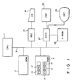
- Fig. 1 is a block diagram showing an embodiment of the present invention.
- central processing unit (CPU) 1 is connected to system bus 3, and executes processing as shown in Figs. 2A through 9.
- Read only memory (ROM) 5 is connected to system bus 3, and stores processing programs as shown in Figs. 2A through 9, executed by CPU 1, such as basic input/output program (BIOS) for a CRT display apparatus, a BIOS for a keyboard, and the like.
- BIOS basic input/output program
- ROM 5 also stores font pattern data having predetermined matrix arrangements (in this embodiment, 8 ⁇ 8 dots, 8 ⁇ 14 dots, and 8 ⁇ 16 dots).
- Main memory 7 comprises a random access memory (RAM), and is connected to system bus 3.
- RAM 7 has registers storing flag data. The flag data are as follows:
- Keyboard (KB) 19 is connected to system bus 3 via keyboard controller (KBC) 21, and supplies data corresponding to a depressed key to CPU 1 via system bus 3.
- keyboard 19 includes a double/single switch key for switching a display character font (single font/double font) in a text mode, a PDP switch key for instructing the switching from the CRT mode to a PDP mode, a CRT switch key for instructing the switching from the PDP mode to the CRT mode, a stretch switch key for switching a display mode (stretch mode/normal mode) of plasma display (PDP) 23 to a graphics mode, and the like.
- PDP 23 displays image data from V-RAM 29 under the control of CRT controller (CRTC) 27 in the same manner as in CRT display apparatus (CRT) 25.
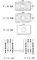
- Display modes of the PDP include display mode A of 640 (horizontal) ⁇ 350 (vertical) dots shown in Fig. 10A, and default display mode B of 640 (horizontal) ⁇ 400 (vertical) dots shown in Fig. 10B.
- raster stretch by 7th-dot double scan is performed as shown in Figs. 11A and 11B only in display mode A in accordance with stretch display control (to be described later), so that a displayed figure in display mode A is approximated to that on CRT display 25.
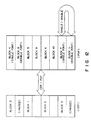
- Fig. 12 shows a storage state of display character fonts used in the text mode.
- specific memory plane A e.g., second plane of first to fourth planes
- another specific plane B e.g., third plane
- PDP 23 a display character font storage section for PDP 23.
- two types of fonts e.g., single and double fonts, are stored in units of blocks.
- Fig. 13 shows the relationship between various display modes and flags in the embodiment of the present invention. Symbols in Fig. 13 have the following meanings:
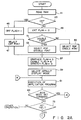
- Fig. 2 is a flow chart showing processing of the PDP/CRT controller of the present invention.
- CPU 1 reads out the content of RAM 7.
- CPU 1 checks in step 43 if the content read out from RAM 7 corresponds to the CRT mode or plasma display (PDP) mode. If YES in step 43, CPU 1 sets "1" representing the CRT mode in FC 9 in step 45. In step 47, CPU 1 selects a CRT font.
- PDP plasma display
- step 51 CPU 1 refers to RAM 7 to check if a display character font in use is a single or double font. If a single font is used in step 51, CPU 1 selects one of blocks 4 through 7 in Fig. 12. However, if a double font is used in step 51, CPU 1 selects one of blocks 8 through 11 in Fig. 12.
- the PDP mode is selected as a display mode for a display
- a single font is selected as a display character font
- CPU 1 selects a default display mode as the PDP display mode (in this embodiment, 640 ⁇ 400 dot matrix shown in Fig. 10B) based on a CRT.BIOS stored in ROM 5 in step 59.
- CPU 1 then executes an application program in step 61.
- CPU 1 checks in step 63 if a BIOS mode set command is generated during execution of the application program. If YES in step 63, the flow advances to step 65, and CPU 1 executes a BIOS mode set routine.
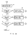
- CPU 1 checks in step 67 if an alteration request of a display mode is input. If NO in step 67, CPU 1 executes text mode processing in step 69.
- step 67 CPU 1 checks in step 71 if the display screen (640 ⁇ 350 dots) in display mode A shown in Fig. 10A is set. If YES in step 71, CPU 1 executes 640 ⁇ 350 graphics mode processing in step 73. However, if NO in step 71, CPU 1 checks in step 75 if a 100 ⁇ 400 graphics mode is set. If YES in step 75, CPU 1 executes 640 ⁇ 400 graphics mode processing in step 77.
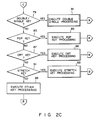
- step 78 it is checked in step 78 if a key input at keyboard 19 is made. If YES in step 78, it is checked In step 79 shown in Fig. 2C if the double font/single font switch key is depressed. If YES in step 79, double font/single font switching processing is executed in step 81.
- step 83 CPU 1 checks in step 83 if a key operated at keyboard 19 is the PDP key instructing switching from the CRT mode to the PDP mode. If YES in step 83, CPU 1 executes a PDP key processing subroutine in step 85. However, if NO in step 83, it is checked in step 87 if the operated key is the CRT key for instructing switching from the PDP mode to the CRT mode. If YES in step 87, CPU 1 executes a CRT key processing subroutine in step 89. However, if NO in step 87, CPU 1 checks in step 91 if the operated key is the stretch key for switching the display mode (stretch mode/normal mode) of PDP 23. If YES in step 91, CPU 1 executes a stretch key processing subroutine in step 93.
- step 91 CPU 1 executes processing for other input keys in step 95.
- Fig. 3 shows a subroutine of processing of the display screen in display mode A. If CPU 1 determines in step 71 in Fig. 2B that the 640 ⁇ 350 graphics mode is set, it alters the display screen (640 ⁇ 400 dots) in default display mode B shown in Fig. 10B to the display screen (640 ⁇ 350 dots) in display mode A shown in Fig. 10A. More specifically, in step 97 in Fig. 3, CPU 1 sets "1" representing the graphics mode in FG 13, and thereafter, refers to FC 9 in step 99. If it is determined in step 99 that "1" representing the display mode of CRT 25 (CRT mode) is set in FC 9, CPU 1 sets "0" indicating a stretch disable mode in FE 17 in step 109. As a result, CPU 1 performs CRT display control in the normal mode for CRT 25. Fig. 10C shows a display screen format on CRT 25 in this case, and Fig. 13 shows the states of flags.
- step 99 if it is determined in step 99 that "0" indicating the display mode for PDP 23 is set in FC 9, CPU 1 sets "1" indicating a stretch enable mode in FE 17 in step 101.
- step 103 CPU 1 refers to FS 15. If it determined in step 103 that "0" indicating the normal mode is set in FS 15, CPU 1 performs display control in the normal mode for PDP 23 in step 107.
- Fig. 10A shows a display screen format on PDP 23 in this case, and Fig. 13 shows states of flags.
- FS "0" in M6.
- stretch processing is not performed, and an image is displayed on PDP 23 using the display screen (640 ⁇ 350 dots) in display mode A shown in Fig. 10A.
- the display screen (640 ⁇ 350 dots) in display mode A shown in Fig. 10A has no correspondence in real image with CRT 25, but can clearly display a font.
- step 103 If it is determined in step 103 that "1" indicating the stretch mode (raster stretch mode) is set in FS 15, CPU 1 performs PDP display control in the stretch mode for PDP 23.
- Fig. 10B shows a display screen format on PDP 23 in this case, and Fig. 13 shows states of flags.
- FS "1" in M6.
- a 7th dot of display image data (Fig. 11A) read out from V-RAM 29 and displayed on PDP 23 is scanned twice to achieve raster stretch processing.
- an image is expanded and displayed in the same dot matrix as in the display screen format (640 ⁇ 400 dots) in the default display mode shown in Fig. 10B. (350 dots in the vertical direction are expanded to 400 dots.)
- step 75 in Fig. 2B If it is determined in step 75 in Fig. 2B that the display screen (640 ⁇ 400 dots) in display mode B is set, CPU 1 then executes a 640 ⁇ 400 graphics mode processing subroutine shown in Fig. 4. More specifically, in step 113 in Fig. 4, CPU 1 sets "1" indicating the graphics mode in FG 13, and sets "0" indicating the stretch disable mode in FE 17. In step 115, CPU 1 performs PDP display control in the normal mode. Fig. 10B shows the display screen format on PDP 23 in this case, and M4 in Fig. 13 shows the flag states. In this case, FE 17 is set to be "0" indicating the stretch disable mode, and stretch processing is disabled. Therefore, an image is displayed on PDP 23 using the display screen (640 ⁇ 400 dots) in display mode A shown in Fig. 10B.
- CPU 1 executes a text mode processing subroutine in step 69. More specifically, in step 117 in Fig. 5, CPU 1 sets "0" in FG 13 and FE 17. In step 119, CPU 1 refers to FC 9. If FC 9 is set to be "1" indicating the CRT mode, a CRT font (blocks 0 through 3 in Fig. 12) is selected as a display character font in step 123. Fig. 10C shows the display screen format on CRT 25 in this case, and M3 in Fig. 13 shows the flag states.
- step 119 CPU 1 determines that the PDP mode is CPU 1 then refers to FD 11 in step 121. If FD 11 is set to be "1" indicating a double font, CPU 1 selects the double font (blocks 8 through 11 in Fig. 12) as a display character font in step 125. If it is determined in step 121 that FD 11 is set to be "0"' CPU 1 determines that the single font is set, and selects a single font (blocks 4 through 7 in Fig. 12) as a display character font in step 127.
- Fig. 10B shows the display screen format on PDP 23 in this case, and M2 (double font) and M1 (single font) in Fig. 13 show flag states.
- step 129 CPU 1 sets a normal scan mode.
- a display character font with a good visual recognition property corresponding to use environment, an object to be processed, and the like, can be arbitrarily used.
- the display mode (graphics mode/text mode) is set and altered.
- step 79 in Fig. 2C If it is determined in step 79 in Fig. 2C that the operated key is the double/single switch key for switching the display character font (single font/double font) in the text mode, double/single switching processing shown in Fig. 6 is executed. That is, it is checked in step 131 if FG 13 is set to be “0" indicating the text mode. If "0”, it is checked in step 133 if FC 9 is set to be "0" indicating the PDP mode. If “0”, the flow advances to step 135, and CPU 1 refers to FD 11.
- step 135 If it is determined in step 135 that FD 11 is set to be "1" indicating a double font, CPU 1 sets "0" in FD 11 in step 137, and selects a single font as a display character font in accordance with the content of FD 11 in step 139.
- step 135 If it is determined in step 135 that FD 11 is set to be "0" indicating a single font, CPU 1 rewrites FD 11 to be "1" in step 141, and selects blocks 8 through 11 in Fig. 12 based on the content of FD 11 in step 143.
- step 83 in Fig. 2C If it is determined in step 83 in Fig. 2C that the PDP key for instructing switching from the CRT mode to the PDP mode is operated, processing shown in Fig. 7 is executed. More specifically, if it is determined in step 145 in Fig. 7 that FC 9 is set to be "1" indicating the CRT mode, display switching processing from the CRT to the PDP including timing switching processing of CRTC 27 is executed in step 147.
- step 149 CPU 1 refers to FG 13. If it is determined in step 149 that FG 13 is set to be "1”, CPU 1 refers to FS 15 in step 151. If it is determined in step 151 that FS 15 is set to be "1" indicating the stretch mode (raster stretch mode), PDP display control in the stretch mode for PDP 23 is performed in step 155.
- step 151 If it is determined in step 151 that FS 15 is set to be "0" indicating the normal mode, PDP display control in the normal mode for PDP 23 is performed in step 153.
- step 149 If it is determined in step 149 that FG 13 is set to be "0" indicating the text mode, CPU 1 refers to FD 11 in step 157. If it is determined in step 157 that FD 11 is set to be "0" indicating a single font, CPU 1 selects a single font (blocks 4 through 7 in Fig. 12) as a display character font of PDP 23 in step 159. If it is determined in step 157 that FD 11 is set to be "1" indicating a double font, CPU 1 selects a double font (blocks 8 through 11 in Fig. 12) as a display character font of PDP 23 in step 161.
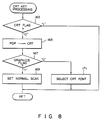
- step 97 in Fig. 2C If it is determined in step 97 in Fig. 2C that the CRT key for instructing switching from the PDP mode to the CRT mode is operated, CPU 1 executes a CRT key processing routine shown in Fig. 8. More specifically, if it is determined in step 163 in Fig. 8 that FC 9 is set to be "0" indicating the PDP mode, the flow advances to step 165, and display switching processing from the PDP to CRT including timing switching processing of CRTC 27 is executed. In step 167, CPU 1 refers to FG 13 in step 167. If it is determined in step 167 that FG 13 is set to be "1" indicating the graphics mode, CRT graphics display control in the normal mode for CRT 25 is executed in step 169. However, if it is determined in step 167 that FG is set to be "0" indicating the text mode, a CRT font (blocks 0 through 3 in Fig. 12) is selected as a text display character font of CRT 25 in step 171.
- step 91 in Fig. 2C stretch key processing shown in Fig. 9 is executed. More specifically, if it is determined in step 173 in Fig. 9 that FC 9 is set to be "0" indicating the PDP mode and in step 175 that FE 17 is set to be “1" indicating the stretch enable mode, the flow advances to step 177. If CPU 1 determines in step 177 that FS 15 is set to be "0" indicating the normal mode, it rewrites FS 15 to be "1" indicating the stretch (raster stretch) mode in step 179. In step 181, CPU 1 double-scans a 7th dot, thereby performing raster stretch processing. As a result, PDP display control in the stretch mode for PDP 23 is executed.
- step 177 if it is determined in step 177 that FS 15 is set to be "1”, CPU 1 rewrites FS 15 to be "0" in step 183. In step 185, CPU 1 performs display control in the normal mode based on the content of FS 15.
- the PDP can switch two types of display screen formats, and stretch processing from 8 dots to 9 dots is performed by 7th-dot double scan.
- the present invention is not limited to this.
- three or more display modes, three or more display screen formats, or another stretch means be employed.
Landscapes
- Engineering & Computer Science (AREA)
- Theoretical Computer Science (AREA)
- Physics & Mathematics (AREA)
- General Physics & Mathematics (AREA)
- Computer Hardware Design (AREA)
- Computer Graphics (AREA)
- Plasma & Fusion (AREA)
- Human Computer Interaction (AREA)
- General Engineering & Computer Science (AREA)
- Radar, Positioning & Navigation (AREA)
- Remote Sensing (AREA)
- Controls And Circuits For Display Device (AREA)
- Control Of Indicators Other Than Cathode Ray Tubes (AREA)
Claims (8)
- Système de commande d'affichage pour un système d'ordinateur comprenant un appareil d'affichage à panneau plat (23) et un appareil d'affichage à tube à rayons cathodiques (CRT) optionnel (25) chacun ayant un écran d'affichage avec la capacité de générer sélectivement une image d'affichage comprenant une pluralité de lignes de trame et dans lequel ledit système de commande d'affichage est couplé à une mémoire V-RAM (Vidéo-RAM)(29) et un dispositif de commande d'affichage (1, 5) pour retrouver des données de ligne à partir de la mémoire V-RAM (29) et pour commander sélectivement soit l'appareil d'affichage à panneau plat (23) soit l'appareil d'affichage CRT (25) pour afficher les données de ligne sur l'écran d'affichage de l'appareil d'affichage sélectionné, le système de commande d'affichage ayant un mode d'affichage courant sélectionnable entre une pluralité de modes d'affichage, ledit dispositif de commande d'affichage (1, 5) comprenant :
un dispositif de désignation d'allongement pour générer sélectivement une instruction d'allongement pour provoquer l'allongement de l'image d'affichage de l'appareil d'affichage à panneau plat (23) ;
un premier dispositif de stockage (15) pour stocker des premières données en réponse à ladite instruction d'allongement ;
un second dispositif de stockage (17) pour stocker des secondes données représentant le mode d'affichage courant utilisé pour déterminer si l'image d'affichage peut être allongée ;
un dispositif de discrimination (1, 5, 7) pour discriminer, sur la base des premières données stockées dans le premier dispositif de stockage et les secondes données stockées dans ledit second dispositif de stockage (17), si oui ou non l'image d'affichage dudit appareil d'affichage à panneau plat (23) peut être allongée lorsque l'image d'affichage est générée sur ledit écran d'affichage dudit appareil d'affichage à panneau plat ; et
un dispositif d'allongement d'image (1, 5, 15), lorsque le dispositif de discrimination (1, 5, 7) discrimine que l'image d'affichage peut être allongée, pour retrouver répétitivement et pour afficher à partir de la mémoire V-RAM, à des intervalles régulièrement distribués, des données de ligne correspondant à une ligne de trame spécifique de l'écran d'affichage de l'appareil d'affichage à panneau plat afin d'ajouter au moins une ligne supplémentaire à ladite image d'affichage dudit écran d'affichage, allongeant ainsi l'image d'affichage. - Système selon la revendication 1, caractérisé en ce que le dispositif de discrimination (1, 5, 7) comprend en outre un dispositif pour déterminer si une résolution d'un type d'image d'affichage dudit appareil d'affichage à panneau plat (23) n'est pas un écran d'affichage entier lorsqu'un programme d'application pour un appareil d'affichage CRT (25) est en cours d'exécution utilisant ledit appareil d'affichage à panneau plat (23).
- Système selon la revendication 1, caractérisé en ce que le système d'ordinateur comprend en outre un clavier (19) comprenant une touche d'allongement, et caractérisé en outre par un dispositif comprenant pour introduire par la touche d'allongement ladite désignation d'allongement, provoquant un allongement de l'image affichée par l'appareil d'affichage à panneau plat (23).
- Système selon la revendication 3, caractérisé en ce que ledit dispositif de discrimination (1, 5, 7) comprend en outre un dispositif pour déterminer si l'image d'affichage dudit appareil d'affichage à panneau plat (23) peut être allongée lorsque la touche d'allongement est appuyée.
- Procédé de génération d'un écran d'affichage ayant une pluralité de lignes de trame par un système d'ordinateur comprenant une mémoire V-RAM (vidéo-RAM) (29) capable de maintenir des données d'affichage, un appareil d'affichage à panneau plat (23), et un appareil à tube à rayons cathodiques (CRT) optionnel (25), ledit système d'ordinateur fonctionnant en mode d'affichage courant se composant d'un mode sélectionné d'une pluralité de modes d'affichage, et le système d'ordinateur comprenant un dispositif de commande d'affichage (1, 5) pour commander sélectivement soit l'appareil d'affichage à panneau plat soit l'appareil d'affichage à CRT (25), ledit procédé comprenant les étapes de :
génération d'une instruction d'allongement en réponse à une demande reçue qu'une image d'affichage de l'appareil d'affichage à panneau plat (23) soit à allonger et de stockage de premières données dans un premier dispositif de stockage (15) en réponse à l'instruction d'allongement générée ;
stockage de secondes données représentant le mode d'affichage courant dans un second dispositif de stockage (17) à utiliser pour déterminer si l'image d'affichage peut être allongée,
discrimination, sur la base desdites première et seconde données stockées dans les premier et second dispositifs de stockage (15, 17), si oui ou non l'image d'affichage dudit appareil d'affichage à panneau plat (23) peut être allongée lorsque l'image d'affichage est générée sur ledit écran d'affichage dudit appareil d'affichage à panneau plat (23) ; et
de lecture et d'affichage de données d'affichage correspondant à une ligne de trame spécifique de l'écran d'affichage de l'appareil d'affichage à panneau plat à partir de la mémoire V-RAM (29) une pluralité de fois à des intervalles distribués régulièrement afin d'ajouter au moins une ligne de trame supplémentaire à ladite image d'affichage, allongeant ainsi ladite image d'affichage, si l'étape de discrimination discrimine que l'image d'affichage peut être allongée. - Procédé selon la revendication 5, caractérisé en ce que l'étape de discrimination comprend en outre l'étape de détermination si une résolution d'un type d'image d'affichage dudit appareil d'affichage à panneau plat (239) n'est pas un plein écran d'affichage lorsqu'un programme d'application pour un appareil d'affichage à CRT (25) est en cours d'exécution utilisant ledit appareil d'affichage à panneau plat (23).
- Procédé selon la revendication 5, caractérisé en ce que le système d'ordinateur comprend en outre un clavier (19) comprenant une touche d'allongement, et caractérisé en ce qu'il comprend en outre l'étape d'introduction à l'aide de la touche d'allongement d'une demande pour allonger l'image d'affichage dudit appareil d'affichage à panneau plat (23).
- Procédé selon la revendication 7, caractérisé en ce que l'étape de discrimination comprend en outre l'étape de détermination si l'image d'affichage dudit appareil d'affichage à panneau plat (23) peut être allongée lorsque la touche d'allongement est appuyée.
Applications Claiming Priority (6)
| Application Number | Priority Date | Filing Date | Title |
|---|---|---|---|
| JP152701/87 | 1987-06-19 | ||
| JP15270187 | 1987-06-19 | ||
| JP289501/87 | 1987-11-18 | ||
| JP289502/87 | 1987-11-18 | ||
| JP62289502A JP2888522B2 (ja) | 1987-06-19 | 1987-11-18 | 表示制御装置 |
| JP62289501A JPS6477090A (en) | 1987-06-19 | 1987-11-18 | Display switch control system for plasma display |
Publications (3)
| Publication Number | Publication Date |
|---|---|
| EP0295692A2 EP0295692A2 (fr) | 1988-12-21 |
| EP0295692A3 EP0295692A3 (fr) | 1991-03-13 |
| EP0295692B1 true EP0295692B1 (fr) | 1994-11-23 |
Family
ID=27320328
Family Applications (1)
| Application Number | Title | Priority Date | Filing Date |
|---|---|---|---|
| EP88109672A Expired - Lifetime EP0295692B1 (fr) | 1987-06-19 | 1988-06-16 | Dispositif de commande d'affichage pour un appareil à TRC/plasma |
Country Status (4)
| Country | Link |
|---|---|
| US (1) | US5430457A (fr) |
| EP (1) | EP0295692B1 (fr) |
| KR (1) | KR910005366B1 (fr) |
| DE (1) | DE3852149T2 (fr) |
Families Citing this family (24)
| Publication number | Priority date | Publication date | Assignee | Title |
|---|---|---|---|---|
| KR900702469A (ko) * | 1988-09-16 | 1990-12-07 | 원본미기재 | 디스플레이를 위한 페이크아웃(fakeout) 방법 및 회로 |
| US5222212A (en) * | 1988-09-16 | 1993-06-22 | Chips And Technologies, Inc. | Fakeout method and circuitry for displays |
| JP3126360B2 (ja) * | 1989-09-01 | 2001-01-22 | キヤノン株式会社 | 表示システム及びその表示制御方法 |
| JPH03225392A (ja) * | 1990-01-30 | 1991-10-04 | Mitsubishi Electric Corp | テキスト表示装置 |
| JPH03225393A (ja) * | 1990-01-30 | 1991-10-04 | Mitsubishi Electric Corp | テキスト表示装置 |
| JPH043279A (ja) * | 1990-04-20 | 1992-01-08 | Canon Inc | 画像読み取り装置 |
| JPH0519747A (ja) * | 1991-07-09 | 1993-01-29 | Toshiba Corp | 表示制御装置 |
| JPH0944113A (ja) * | 1995-07-28 | 1997-02-14 | Sony Corp | Lcd駆動用タイミングジェネレータ |
| JPH09114428A (ja) * | 1995-10-19 | 1997-05-02 | Hitachi Ltd | 情報処理装置 |
| JP3713084B2 (ja) * | 1995-11-30 | 2005-11-02 | 株式会社日立製作所 | 液晶表示制御装置 |
| KR200160668Y1 (ko) * | 1997-12-16 | 1999-11-15 | 윤종용 | 평판 디스플레이 장치 및 이를 사용하는 디지탈 데이터 처리 장치 |
| US7554510B1 (en) * | 1998-03-02 | 2009-06-30 | Ati Technologies Ulc | Method and apparatus for configuring multiple displays associated with a computing system |
| US6028571A (en) * | 1998-03-05 | 2000-02-22 | Paradise Electronics, Inc. | Digital display unit in a computer system with an improved method and apparatus for determining a source mode using which a received analog display signal was generated |
| US6138193A (en) * | 1998-06-23 | 2000-10-24 | Compaq Computer Corporation | System for reducing noise in bus having plurality of first and second set of signals and a delay device for delaying propagation of second signals |
| KR100524904B1 (ko) * | 1998-07-09 | 2005-12-21 | 삼성전자주식회사 | 그래픽램및그래픽램을내장한액정표시장치드라이버 |
| US6670964B1 (en) * | 1998-09-18 | 2003-12-30 | Hewlett-Packard Development Company, L.P. | Automatic scaler mode detection |
| US6295048B1 (en) | 1998-09-18 | 2001-09-25 | Compaq Computer Corporation | Low bandwidth display mode centering for flat panel display controller |
| US6894706B1 (en) | 1998-09-18 | 2005-05-17 | Hewlett-Packard Development Company, L.P. | Automatic resolution detection |
| US6674436B1 (en) * | 1999-02-01 | 2004-01-06 | Microsoft Corporation | Methods and apparatus for improving the quality of displayed images through the use of display device and display condition information |
| JP2001186454A (ja) * | 1999-12-24 | 2001-07-06 | Matsushita Electric Ind Co Ltd | 光ディスク再生装置 |
| US6823525B1 (en) * | 2000-01-21 | 2004-11-23 | Ati Technologies Inc. | Method for displaying single monitor applications on multiple monitors driven by a personal computer |
| US20030011534A1 (en) * | 2001-07-13 | 2003-01-16 | International Business Machines Corporation | Display privacy for enhanced presentations with real-time updates |
| US20030156639A1 (en) * | 2002-02-19 | 2003-08-21 | Jui Liang | Frame rate control system and method |
| JP3898091B2 (ja) * | 2002-06-03 | 2007-03-28 | Necディスプレイソリューションズ株式会社 | 画像表示装置および画像表示装置の制御方法 |
Family Cites Families (32)
| Publication number | Priority date | Publication date | Assignee | Title |
|---|---|---|---|---|
| JPS5137851B2 (fr) * | 1971-09-25 | 1976-10-18 | ||
| DE2213953C3 (de) * | 1972-03-22 | 1978-04-27 | Siemens Ag, 1000 Berlin Und 8000 Muenchen | Schaltungsanordnung zum Darstellen von Zeichen auf dem Bildschirm eines Sichtgerätes |
| GB1461929A (en) * | 1974-07-11 | 1977-01-19 | British Broadcasting Corp | Data display systems |
| US3928845A (en) * | 1974-12-11 | 1975-12-23 | Rca Corp | Character generator system selectively providing different dot-matrix size symbols |
| US4121283A (en) * | 1977-01-17 | 1978-10-17 | Cromemco Inc. | Interface device for encoding a digital image for a CRT display |
| US4430649A (en) * | 1978-07-21 | 1984-02-07 | Radio Shack | Video processing system |
| GB2053533B (en) * | 1979-07-06 | 1983-05-18 | Digital Equipment Corp | Digital data communications device with standard option connection |
| JPS56122132U (fr) * | 1980-02-18 | 1981-09-17 | ||
| JPS5773793A (en) * | 1980-10-27 | 1982-05-08 | Sony Corp | Video display unit driving system |
| US4454593A (en) * | 1981-05-19 | 1984-06-12 | Bell Telephone Laboratories, Incorporated | Pictorial information processing technique |
| US4422163A (en) * | 1981-09-03 | 1983-12-20 | Vend-A-Copy, Inc. | Power down circuit for data protection in a microprocessor-based system |
| US4536856A (en) * | 1982-06-07 | 1985-08-20 | Sord Computer Systems, Inc. | Method of and apparatus for controlling the display of video signal information |
| US4574279A (en) * | 1982-11-03 | 1986-03-04 | Compaq Computer Corporation | Video display system having multiple selectable screen formats |
| US4566005A (en) * | 1983-03-07 | 1986-01-21 | International Business Machines Corporation | Data management for plasma display |
| DE3438081A1 (de) * | 1983-10-17 | 1985-05-02 | Canon K.K., Tokio/Tokyo | Bildverarbeitungssystem |
| JPS6085678A (ja) * | 1983-10-17 | 1985-05-15 | Canon Inc | 画像表示装置 |
| US4611203A (en) * | 1984-03-19 | 1986-09-09 | International Business Machines Corporation | Video mode plasma display |
| DE3586927T2 (de) * | 1984-04-20 | 1993-06-03 | Hitachi Ltd | Flaches bildschirmanzeigesystem mit integriertem eingabegeraet. |
| JPS60227296A (ja) * | 1984-04-25 | 1985-11-12 | シャープ株式会社 | 表示制御方式 |
| JPS60233690A (ja) * | 1984-05-07 | 1985-11-20 | キヤノン株式会社 | 表示装置 |
| US4628534A (en) * | 1984-07-06 | 1986-12-09 | Honeywell Information Systems Inc. | Method for changing the resolution of compressed image data |
| US4727362A (en) * | 1984-07-16 | 1988-02-23 | International Business Machines Corporation | Digital display system |
| WO1986003610A1 (fr) * | 1984-12-06 | 1986-06-19 | Dainippon Screen Mfg. Co., Ltd. | Procede et appareil de compression de donnees video |
| JPS61213896A (ja) * | 1985-03-19 | 1986-09-22 | 株式会社 アスキ− | デイスプレイコントロ−ラ |
| JPH0736104B2 (ja) * | 1985-03-27 | 1995-04-19 | 株式会社アスキ− | デイスプレイコントロ−ラ |
| US4763279A (en) * | 1985-12-26 | 1988-08-09 | International Business Machines Corporation | Method and apparatus for converting dot matrix display data of one resolution to a format for displaying on a display device having a different resolution |
| JPS63132281A (ja) * | 1986-11-25 | 1988-06-04 | 富士通株式会社 | 文字サイズ拡大変換表示制御方式 |
| EP0295690B1 (fr) * | 1987-06-19 | 1994-11-30 | Kabushiki Kaisha Toshiba | Système de commande de la zone de visualisation pour un dispositif d'affichage à plasma |
| EP0295691B1 (fr) * | 1987-06-19 | 1994-11-23 | Kabushiki Kaisha Toshiba | Système de commutation du mode d'affichage pour un appareil de visualisation à plasma |
| EP0295689B1 (fr) * | 1987-06-19 | 1995-03-29 | Kabushiki Kaisha Toshiba | Dispositif de commande d'affichage pour une appareil de visualisation à TRC/plasma |
| JPH01191914A (ja) * | 1988-01-27 | 1989-08-02 | Toshiba Corp | コンピュータシステム |
| JP2892010B2 (ja) * | 1988-05-28 | 1999-05-17 | 株式会社東芝 | 表示制御方式 |
-
1988
- 1988-06-16 DE DE3852149T patent/DE3852149T2/de not_active Expired - Lifetime
- 1988-06-16 EP EP88109672A patent/EP0295692B1/fr not_active Expired - Lifetime
- 1988-06-18 KR KR1019880007431A patent/KR910005366B1/ko not_active Expired
-
1994
- 1994-09-30 US US08/315,489 patent/US5430457A/en not_active Expired - Lifetime
Also Published As
| Publication number | Publication date |
|---|---|
| KR890001011A (ko) | 1989-03-17 |
| DE3852149T2 (de) | 1995-04-06 |
| KR910005366B1 (ko) | 1991-07-29 |
| US5430457A (en) | 1995-07-04 |
| DE3852149D1 (de) | 1995-01-05 |
| EP0295692A3 (fr) | 1991-03-13 |
| EP0295692A2 (fr) | 1988-12-21 |
Similar Documents
| Publication | Publication Date | Title |
|---|---|---|
| US5430457A (en) | CRT/flat panel display control system | |
| US5351064A (en) | CRT/flat panel display control system | |
| CA1213085A (fr) | Methode et appareil de compression et de manipulation d'images | |
| KR930004439B1 (ko) | 문자사이즈에 의해 복수종의 아우트라인 폰트를 사용하는 문서작성장치 | |
| US4529978A (en) | Method and apparatus for generating graphic and textual images on a raster scan display | |
| JPH0469794B2 (fr) | ||
| US5379051A (en) | Method and apparatus for rearranging and displaying line data | |
| KR900008594B1 (ko) | 디스플레이 제어 시스템 및 방법 | |
| EP0395916A2 (fr) | Système de visualisation avec police de charactère et attribut séparé | |
| CA1199437A (fr) | Methode pour structurer un jeu d'affichage a densite elevee pour dispositif d'affichage de systeme de traitement de texte | |
| JP3184979B2 (ja) | デジタル活字面の輪郭を形成する方法およびその装置 | |
| EP0356262B1 (fr) | Appareil de traitement d'images | |
| EP0062669B1 (fr) | Generateur d'image graphique et de texte pour un affichage a balayage a canevas | |
| EP0258825B1 (fr) | Dispositif de contrôle d'affichage avec fonction d'attribut améliorée | |
| JPS6329291B2 (fr) | ||
| JP3228952B2 (ja) | 情報処理装置および表示制御回路 | |
| EP0770301B1 (fr) | Procede et appareil de compression de donnees d'image | |
| JPS6327727B2 (fr) | ||
| US6281982B1 (en) | Information processing apparatus, information processing method, storage medium, and printing system | |
| US5659336A (en) | Method and apparatus for creating and transferring a bitmap | |
| EP0128289B1 (fr) | Visualisation de données graphiques dans un dispositif d'affichage sans possibilité d'adresser tous les points | |
| JP3407537B2 (ja) | 帳票出力方法 | |
| JPH0456317B2 (fr) | ||
| JPH04188192A (ja) | 多階調文字発生方法及びその装置 | |
| JPH05323280A (ja) | 表示制御方式 |
Legal Events
| Date | Code | Title | Description |
|---|---|---|---|
| PUAI | Public reference made under article 153(3) epc to a published international application that has entered the european phase |
Free format text: ORIGINAL CODE: 0009012 |
|
| 17P | Request for examination filed |
Effective date: 19880713 |
|
| AK | Designated contracting states |
Kind code of ref document: A2 Designated state(s): DE FR GB |
|
| PUAL | Search report despatched |
Free format text: ORIGINAL CODE: 0009013 |
|
| AK | Designated contracting states |
Kind code of ref document: A3 Designated state(s): DE FR GB |
|
| 17Q | First examination report despatched |
Effective date: 19930318 |
|
| GRAA | (expected) grant |
Free format text: ORIGINAL CODE: 0009210 |
|
| AK | Designated contracting states |
Kind code of ref document: B1 Designated state(s): DE FR GB |
|
| REF | Corresponds to: |
Ref document number: 3852149 Country of ref document: DE Date of ref document: 19950105 |
|
| ET | Fr: translation filed | ||
| PLBE | No opposition filed within time limit |
Free format text: ORIGINAL CODE: 0009261 |
|
| STAA | Information on the status of an ep patent application or granted ep patent |
Free format text: STATUS: NO OPPOSITION FILED WITHIN TIME LIMIT |
|
| 26N | No opposition filed | ||
| REG | Reference to a national code |
Ref country code: GB Ref legal event code: IF02 |
|
| PGFP | Annual fee paid to national office [announced via postgrant information from national office to epo] |
Ref country code: DE Payment date: 20070614 Year of fee payment: 20 |
|
| PGFP | Annual fee paid to national office [announced via postgrant information from national office to epo] |
Ref country code: GB Payment date: 20070613 Year of fee payment: 20 |
|
| PGFP | Annual fee paid to national office [announced via postgrant information from national office to epo] |
Ref country code: FR Payment date: 20070608 Year of fee payment: 20 |
|
| REG | Reference to a national code |
Ref country code: GB Ref legal event code: PE20 Expiry date: 20080615 |
|
| PG25 | Lapsed in a contracting state [announced via postgrant information from national office to epo] |
Ref country code: GB Free format text: LAPSE BECAUSE OF EXPIRATION OF PROTECTION Effective date: 20080615 |