EP0297268A2 - Dispositif pour appliquer des colles liquides sur un substrat - Google Patents
Dispositif pour appliquer des colles liquides sur un substrat Download PDFInfo
- Publication number
- EP0297268A2 EP0297268A2 EP88108052A EP88108052A EP0297268A2 EP 0297268 A2 EP0297268 A2 EP 0297268A2 EP 88108052 A EP88108052 A EP 88108052A EP 88108052 A EP88108052 A EP 88108052A EP 0297268 A2 EP0297268 A2 EP 0297268A2
- Authority
- EP
- European Patent Office
- Prior art keywords
- plate
- substrate
- application nozzle
- application
- doctor blade
- Prior art date
- Legal status (The legal status is an assumption and is not a legal conclusion. Google has not performed a legal analysis and makes no representation as to the accuracy of the status listed.)
- Withdrawn
Links
- 239000000758 substrate Substances 0.000 title claims description 24
- 239000007788 liquid Substances 0.000 title claims description 6
- 239000003292 glue Substances 0.000 title description 3
- 239000000853 adhesive Substances 0.000 claims abstract description 23
- 230000001070 adhesive effect Effects 0.000 claims abstract description 23
- 238000003860 storage Methods 0.000 claims abstract description 9
- 238000003892 spreading Methods 0.000 claims abstract description 7
- 230000007480 spreading Effects 0.000 claims abstract description 7
- 229910000639 Spring steel Inorganic materials 0.000 claims description 2
- 238000000576 coating method Methods 0.000 description 20
- 239000011248 coating agent Substances 0.000 description 19
- 239000004831 Hot glue Substances 0.000 description 8
- 239000010410 layer Substances 0.000 description 5
- 239000000463 material Substances 0.000 description 4
- 239000004753 textile Substances 0.000 description 4
- 238000002844 melting Methods 0.000 description 3
- 230000008018 melting Effects 0.000 description 3
- 239000002184 metal Substances 0.000 description 3
- 238000007650 screen-printing Methods 0.000 description 3
- 230000008859 change Effects 0.000 description 2
- 238000010276 construction Methods 0.000 description 2
- 239000004033 plastic Substances 0.000 description 2
- -1 polytetrafluoroethylene Polymers 0.000 description 2
- 229920001343 polytetrafluoroethylene Polymers 0.000 description 2
- 239000004810 polytetrafluoroethylene Substances 0.000 description 2
- 239000012790 adhesive layer Substances 0.000 description 1
- 238000009826 distribution Methods 0.000 description 1
- 238000005516 engineering process Methods 0.000 description 1
- 230000002349 favourable effect Effects 0.000 description 1
- 239000012943 hotmelt Substances 0.000 description 1
- 238000004519 manufacturing process Methods 0.000 description 1
- 238000000034 method Methods 0.000 description 1
- 238000007639 printing Methods 0.000 description 1
- 230000008569 process Effects 0.000 description 1
- 230000009467 reduction Effects 0.000 description 1
- 238000007789 sealing Methods 0.000 description 1
- 230000002123 temporal effect Effects 0.000 description 1
- 238000011144 upstream manufacturing Methods 0.000 description 1
Images



Classifications
-
- B—PERFORMING OPERATIONS; TRANSPORTING
- B05—SPRAYING OR ATOMISING IN GENERAL; APPLYING FLUENT MATERIALS TO SURFACES, IN GENERAL
- B05C—APPARATUS FOR APPLYING FLUENT MATERIALS TO SURFACES, IN GENERAL
- B05C5/00—Apparatus in which liquid or other fluent material is projected, poured or allowed to flow on to the surface of the work
- B05C5/02—Apparatus in which liquid or other fluent material is projected, poured or allowed to flow on to the surface of the work the liquid or other fluent material being discharged through an outlet orifice by pressure, e.g. from an outlet device in contact or almost in contact, with the work
- B05C5/0254—Coating heads with slot-shaped outlet
- B05C5/0262—Coating heads with slot-shaped outlet adjustable in width, i.e. having lips movable relative to each other in order to modify the slot width, e.g. to close it
-
- B—PERFORMING OPERATIONS; TRANSPORTING
- B05—SPRAYING OR ATOMISING IN GENERAL; APPLYING FLUENT MATERIALS TO SURFACES, IN GENERAL
- B05C—APPARATUS FOR APPLYING FLUENT MATERIALS TO SURFACES, IN GENERAL
- B05C11/00—Component parts, details or accessories not specifically provided for in groups B05C1/00 - B05C9/00
- B05C11/10—Storage, supply or control of liquid or other fluent material; Recovery of excess liquid or other fluent material
-
- D—TEXTILES; PAPER
- D06—TREATMENT OF TEXTILES OR THE LIKE; LAUNDERING; FLEXIBLE MATERIALS NOT OTHERWISE PROVIDED FOR
- D06B—TREATING TEXTILE MATERIALS USING LIQUIDS, GASES OR VAPOURS
- D06B11/00—Treatment of selected parts of textile materials, e.g. partial dyeing
- D06B11/0056—Treatment of selected parts of textile materials, e.g. partial dyeing of fabrics
- D06B11/0066—Treatment of selected parts of textile materials, e.g. partial dyeing of fabrics by spaced contacts with a member carrying a single treating material
Definitions
- the invention relates to a device for applying liquid adhesives to a substrate of the type specified in the preamble of claim 1.
- Such a device can be used both in connection with hot-melt adhesives, also in connection with cold glues, if such adhesives have to be applied to screen-printing rotary cylinders or engraving rollers, but also to flat, for example textile substrates.
- DE-OS 3 248 889 discloses a device for applying surface coatings to a textile substrate, which has a nozzle-shaped mouth gap of a pressurized, bar-shaped coating head, in front of which a perforated metal cylinder rotates as a template.
- the coating head contains a cavity and an orifice chamber which is delimited by two sealing lips and is laterally sealed by a profiled rod which is introduced on both end faces and has the same cross section as that of the orifice chamber; the width of the muzzle chamber can be adjusted by changing profile bars of different lengths or by moving the profile bars.
- the second needle valve is larger than the main valve and is located as a pilot valve in the feed line at a short distance from the main valve, both valves being controllable in an adjustable temporal relationship to one another, so that even at high frequency the application of the adhesive, especially at the beginning and end of Order, done optimally.
- a device for applying liquid adhesives of the type specified finally emerges from DE-PS 35 49 784 and has a storage container and an application nozzle for the adhesive and a shut-off valve in the line from the storage container to the nozzle, which is designed as a slot nozzle, the Slot extends from a spreading chamber; the adhesive is fed to the spreading chamber through a channel which opens centrally into the chamber and which opens into the chamber at an angle to the direction in which the slot adjoins the chamber; the chamber extends substantially on one side of the slot.
- the channel opens into the chamber from the other side of the slot.
- the invention is therefore based on the object of providing a device for applying liquid adhesives of the type specified, in which the disadvantages mentioned above do not occur.
- a device is to be proposed which can be easily and therefore quickly adapted to different layer thicknesses and / or viscosities of the adhesive.
- the advantages achieved by the invention are based on the use of a doctor blade integrated in the application nozzle, which can be easily removed and thus replaced by means of a clamping bracket.
- a doctor blade integrated in the application nozzle, which can be easily removed and thus replaced by means of a clamping bracket.
- the clamping screw has to be loosened, which according to a preferred embodiment is used to fix the doctor blade by means of a clamping plate connected to it.
- the new doctor blade is then inserted into the gap between the clamping plate and the opposite wall of the application head and fixed again by tightening the clamping screw.
- the application nozzle has a beveled, flat surface on its inlet side, which forms an angle with the doctor plate that is less than 90 °; In this way, a kind of storage space for the emerging material is created outside the application nozzle in the space formed by the application nozzle on the one hand and the substrate or the doctor blade on the other.
- the squeegee plate should run at least flush with the corresponding underside of the application nozzle; According to a preferred embodiment, however, the lower end of the application plate protrudes somewhat beyond the corresponding underside of the application nozzle in order to thereby define the storage space mentioned.
- the front edge of the squeegee plate must protrude at least 0.5 mm beyond the part of the application nozzle which is located behind the squeegee plate in the application direction, so that a relatively large free space is available there.
- This application nozzle can be used not only for coating flat substrates, for example textile materials, but also for coating curved substrates, such as printing cylinders, engraving rollers and the like.
- the application process can be adapted to the shape of the substrate, but also to the layer thickness to be applied and the viscosity of the adhesive, by selecting a suitable doctor blade.
- a likewise interchangeable mask plate is used in connection with the doctor blade, which is provided with a recess which serves to adjust the coating width but also the amount of adhesive to be dispensed.
- the application nozzle consists essentially of two relatively thick, plane-parallel plates, as is known from DE-PS 35 41 784, the mask plate is clamped between these two plates, which are held by screws.
- more than one doctor blade can also be used and fixed using the clamping plate; this enables a gradual reduction in pressure at the doctor edge.
- the lower edge of the squeegee plate can be rounded and, for example, in Cross-section have semicircular shape.
- Such a torsion bar can consist of a suitable plastic; good results have been achieved with polytetrafluoroethylene.
- Such a doctor blade ensures clean, intermittent application of adhesives that are difficult to handle, resulting in a closed application system that only applies a precisely defined amount of adhesive.
- This system can be combined with any shut-off valve, for example with the shut-off valve, as is known from the earlier patent application P 35 42 903.8.
- the application nozzle can have the structure known from DE-PS 35 41 784, which offers certain advantages in terms of production technology, which can also be realized in connection with the exchangeable doctor blade or the exchangeable mask plate.
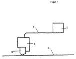
- the device shown schematically in Fig. 1 shows a melting device 2 for a hot melt adhesive, in which this is melted and collected in a molten state in a basin.
- a line 4 extends from this basin to an application head 6; the melted hot melt adhesive is transported by means of a pressure pump provided in the device 2 with a correspondingly high pressure.
- the application head 6 contains a valve device, so that the hot-melt adhesive emerging from the application nozzle 10 located at the bottom of the application head 3 can be applied in precisely defined amounts to the web 8 moving under the application nozzle 10.
- a line can also be provided from the application head 6 for the return of the hot melt adhesive to the melting device 2.
- This return line is always necessary if, due to the valve arrangement used for feeding the nozzle 10, the inflow is not simply shut off, but rather the hot-melt adhesive flowing through line 4 is fed back into a return line (not shown) when the valve is switched over to non-application without braking leads to the melting device 2.
- the application nozzle 10 can have the structure shown in DE-PS 35 41 784, while suitable valve constructions emerge from the earlier patent application P 35 42 903.8.
- the application nozzle indicated in FIG. 2 by the reference numeral 10 essentially consists of two relatively thick, plane-parallel plates 12 and 14 which are screwed together with their surfaces by means of screws.
- a screw 16 is shown in FIG. 2.
- the application nozzle 10 is screwed from below against the application head 6 in a manner not shown in such a way that a feed channel in the application head 6 connects to a bore 18 in the plate 12.
- This bore 18 is connected via a channel 20 to a spreading chamber 22 which is formed in the end face of the plate 12 facing the plate 14.
- a mask 24 made of spring steel (see also FIG. 6) is arranged, which serves to determine the coating thickness and the coating width.
- the mask 24 has a closed surface facing the plate 14 and a recess 25 on its surface facing the plate 12, which extends at least from the spreading chamber 22 to the lower end of the plate 12.
- the width of this cutout 25 shown in FIG. 6 defines the coating width, while the amount of adhesive entering the cutout 25 of the mask 24 from the spreading chamber 22 and thus the coating thickness can be defined by appropriate selection of the depth of the cutout 25.
- the mask 24 is simultaneously fixed between the two plates 12, 14; the holes for the passage of the screws 16 are indicated in FIG. 6 by the reference number 23.
- the end face of the plate 14 facing the plate 12 has a recess in which a doctor blade 26 and a clamping plate 28 are arranged, which is connected to a clamping screw 30.
- the clamping plate 28 presses the squeegee plate 26 against the mask 24, so that the squeegee plate 26 is fixed in the position shown in FIG. 2, in which its lower end projects somewhat beyond the lower edges of the two plates 12, 14.
- the doctor blade 26 can be removed and exchanged for another, for example new doctor blade, but also for a doctor blade with different dimensions.
- a substrate 32 is fed under the application nozzle 10, which is moved in the direction of arrow A.
- the plate 12 On the inlet side of the application nozzle 10, the plate 12 has a bevelled end face which forms an angle of less than 90 ° with the direction of the doctor plate 26. This creates a storage space for the adhesive emerging from the mask 24 between the substrate 32 on the one hand and the end face of the plate 12 or the doctor blade 26 on the other hand.
- the lower edge of the squeegee plate 26 can also run flush with the lower edge of the plate 12; According to a preferred embodiment, however, the doctor blade 26, as shown in FIG. 2, protrudes somewhat beyond the lower edge of the plate 12.
- FIG. 2 shows the coating of a planar, for example textile substrate 32
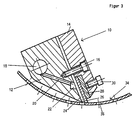
- FIG. 3 shows the coating of a screen printing cylinder 34 with openings 36 through the application nozzle 10, which has the same structure as in the embodiment according to FIG. 2. It can be seen that, with unchanged dimensions, substrates with an internal curvature can also be coated.
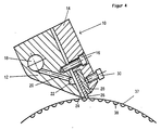
- FIG. 4 shows the application nozzle 10 during the coating of an outwardly curved, cylindrical substrate, namely a gravure engraving roller 37 with depressions 38, which are filled with an adhesive.
- FIG. 5 finally shows a variant of the application nozzle 10, which differs from the previously described variants in that a torsion bar 40 is integrated into the lower edge of the doctor plate 28.
- This torsion bar 40 which can be freely rotated during the coating, lies on the flat substrate 32 and contributes to an evening of the coating.
- the torsion bar can be made of metal or a suitable plastic, in particular polytetrafluoroethylene.
Landscapes
- Engineering & Computer Science (AREA)
- Chemical & Material Sciences (AREA)
- Materials Engineering (AREA)
- Textile Engineering (AREA)
- Coating Apparatus (AREA)
Applications Claiming Priority (2)
| Application Number | Priority Date | Filing Date | Title |
|---|---|---|---|
| DE19873721593 DE3721593A1 (de) | 1987-06-30 | 1987-06-30 | Vorrichtung zum auftragen von fluessigen klebstoffen auf ein substrat |
| DE3721593 | 1987-06-30 |
Publications (2)
| Publication Number | Publication Date |
|---|---|
| EP0297268A2 true EP0297268A2 (fr) | 1989-01-04 |
| EP0297268A3 EP0297268A3 (fr) | 1990-03-14 |
Family
ID=6330594
Family Applications (1)
| Application Number | Title | Priority Date | Filing Date |
|---|---|---|---|
| EP88108052A Withdrawn EP0297268A3 (fr) | 1987-06-30 | 1988-05-19 | Dispositif pour appliquer des colles liquides sur un substrat |
Country Status (4)
| Country | Link |
|---|---|
| US (1) | US4876982A (fr) |
| EP (1) | EP0297268A3 (fr) |
| JP (1) | JP2608927B2 (fr) |
| DE (1) | DE3721593A1 (fr) |
Cited By (3)
| Publication number | Priority date | Publication date | Assignee | Title |
|---|---|---|---|---|
| EP0577136A1 (fr) * | 1992-07-03 | 1994-01-05 | FRIZ MASCHINENBAU GmbH | Dispositif d'application de colle |
| DE19853117B4 (de) * | 1998-05-20 | 2010-04-01 | Barberan, S.A., Castelldefels | Kopfstück zum Auftragen von heißschmelzenden oder aus reaktionsfähigem Polyurethan bestehenden Leimen durch Düsen |
| CN110052365A (zh) * | 2019-05-10 | 2019-07-26 | 北京派和科技股份有限公司 | 一种分体式喷嘴及采用该分体式喷嘴的点胶阀 |
Families Citing this family (40)
| Publication number | Priority date | Publication date | Assignee | Title |
|---|---|---|---|---|
| US5540673A (en) * | 1989-01-31 | 1996-07-30 | The Procter & Gamble Company | Refastenable mechanical fastening system |
| DE3916620A1 (de) * | 1989-05-22 | 1990-12-06 | Jagenberg Ag | Vorrichtung zum beschichten einer um eine gegenwalze gefuehrten materialbahn |
| US5141778A (en) * | 1989-10-12 | 1992-08-25 | Enthone, Incorporated | Method of preparing aluminum memory disks having a smooth metal plated finish |
| JP2740339B2 (ja) * | 1990-07-06 | 1998-04-15 | 大日精化工業株式会社 | インクリボン |
| JPH04361871A (ja) * | 1991-06-06 | 1992-12-15 | Pioneer Electron Corp | クリームハンダ塗布用ディスペンサー |
| BR9206183A (pt) * | 1991-06-21 | 1994-11-22 | Procter & Gamble | Processo para manufaturar um sistema de sujeição, sistema de sujeição e artigo absorvente |
| DE9109785U1 (de) * | 1991-08-07 | 1992-09-17 | J.M. Voith Gmbh, 7920 Heidenheim | Rakelvorrichtung mit Rakelbalken |
| US5628827A (en) * | 1992-09-25 | 1997-05-13 | Minnesota Mining And Manufacturing Company | Non-recirculating, die supplied doctored roll coater with solvent addition |
| US5320037A (en) * | 1992-09-28 | 1994-06-14 | Imtran Industries, Inc. | Enclosed ink cup for pad-type printing machine |
| US5325569A (en) * | 1992-10-30 | 1994-07-05 | The Procter & Gamble Company | Refastenable mechanical fastening system having particular viscosity and rheology characteristics |
| US5392498A (en) * | 1992-12-10 | 1995-02-28 | The Proctor & Gamble Company | Non-abrasive skin friendly mechanical fastening system |
| US5300058A (en) * | 1992-12-10 | 1994-04-05 | The Procter & Gamble Company | Disposable absorbent article having an improved mechanical fastening system |
| DE4303357A1 (de) * | 1993-02-05 | 1994-08-11 | Hoechst Ag | Beschichtungsvorrichtung zum Auftragen dünner Naßfilme |
| US5639305A (en) * | 1994-04-29 | 1997-06-17 | Minnesota Mining And Manufacturing Company | Die coating method and apparatus |
| US5759274A (en) * | 1994-04-29 | 1998-06-02 | Minnesota Mining And Manufacturing Company | Die coating apparatus with surface covering |
| DE4432178A1 (de) * | 1994-09-09 | 1996-03-14 | Voith Gmbh J M | Auftragswerk zum direkten oder indirekten Auftragen eines flüssigen oder pastösen Mediums auf eine laufende Materialbahn |
| DE4432180A1 (de) * | 1994-09-09 | 1996-03-14 | Voith Gmbh J M | Auftragswerk zum direkten oder indirekten Auftragen eines flüssigen oder pastösen Mediums auf eine laufende Materialbahn |
| US5772766A (en) * | 1994-09-09 | 1998-06-30 | Voith Papiermaschinen Gmbh | Application unit for the direct or indirect application of a liquid or pasty medium onto a moving material web |
| US5469786A (en) * | 1994-10-25 | 1995-11-28 | Imtran Industries, Inc. | Enclosed ink cup with improved seal |
| JP2784899B2 (ja) * | 1995-03-14 | 1998-08-06 | 井上金属工業株式会社 | 塗工装置 |
| US6224672B1 (en) * | 1998-12-11 | 2001-05-01 | Illinois Tool Works Inc. | Quick slip die plate and method of mounting and removing the same |
| WO2004078361A1 (fr) * | 2003-03-04 | 2004-09-16 | Nordson Corporation | Composants antiadherents pour dispositif d'application de matiere |
| KR100648411B1 (ko) * | 2003-10-17 | 2006-11-24 | 주식회사 디엠에스 | 유체분사노즐 |
| DE10353916A1 (de) * | 2003-11-18 | 2005-06-09 | Wilhelm Schulte Gmbh | Verfahren zum Verkleben von Textilien |
| DE102007056121B3 (de) * | 2007-11-15 | 2008-09-25 | Lindauer Dornier Gmbh | Breitschlitzdüse und Anlage zum Beschichten mit thermoplastischem Beschichtungsmaterial |
| US8186296B2 (en) | 2010-05-05 | 2012-05-29 | The Procter & Gamble Company | Methods and apparatus for applying adhesives in patterns to an advancing substrate |
| EP2679112A1 (fr) | 2012-06-26 | 2014-01-01 | 3M Innovative Properties Company | Procédé de fabrication de fixations et toiles de précurseurs, élément de fixation et toile de précurseur |
| US9295590B2 (en) | 2012-11-27 | 2016-03-29 | The Procter & Gamble Company | Method and apparatus for applying an elastic material to a moving substrate in a curved path |
| US9248054B2 (en) | 2012-11-27 | 2016-02-02 | The Procter & Gamble Company | Methods and apparatus for making elastic laminates |
| US9265672B2 (en) | 2012-11-27 | 2016-02-23 | The Procter & Gamble Company | Methods and apparatus for applying adhesives in patterns to an advancing substrate |
| JP6647169B2 (ja) * | 2016-07-27 | 2020-02-14 | 富士フイルム株式会社 | 経皮吸収シートの製造方法 |
| CN109046884A (zh) * | 2018-08-31 | 2018-12-21 | 燕山大学 | 一种实验室锂电池极片涂布装置 |
| US11707548B2 (en) | 2018-10-09 | 2023-07-25 | The Procter & Gamble Company | Absorbent article comprising a lotion resistant polymeric filler composition |
| EP3750637A1 (fr) | 2019-03-29 | 2020-12-16 | Airbus Operations GmbH | Dispositif pour transfert de laque |
| EP3722007A1 (fr) | 2019-03-29 | 2020-10-14 | Airbus Operations GmbH | Dispositif de transfert de vernis |
| EP3725539A1 (fr) | 2019-03-29 | 2020-10-21 | Airbus Operations GmbH | Dispositif de transfert de vernis |
| EP3722009A1 (fr) | 2019-03-29 | 2020-10-14 | Airbus Operations GmbH | Dispositif et système |
| EP3733300A1 (fr) | 2019-04-11 | 2020-11-04 | Airbus Operations GmbH | Dispositif pour transfert de laque |
| EP3725422B1 (fr) | 2019-04-12 | 2025-01-29 | Airbus Operations GmbH | Dispositif de transfert de vernis |
| US11554383B2 (en) | 2020-02-17 | 2023-01-17 | Airbus Operations Gmbh | System for lacquer transfer |
Family Cites Families (20)
| Publication number | Priority date | Publication date | Assignee | Title |
|---|---|---|---|---|
| US2328183A (en) * | 1942-05-04 | 1943-08-31 | Minnesota & Ontario Paper Co | Coating apparatus |
| US3377655A (en) * | 1966-03-02 | 1968-04-16 | Eastman Kodak Co | Extrusion die |
| US3690297A (en) * | 1969-07-22 | 1972-09-12 | Blandin Paper Co | Non-aqueous coating of webs |
| US3762365A (en) * | 1972-02-24 | 1973-10-02 | Polytype Ag | Web coating apparatus |
| DE2614596C3 (de) * | 1976-04-05 | 1980-03-13 | Vereinigte Glaswerke Gmbh, 5100 Aachen | Abstreichgießkopf zum Aufbringen gießfähiger Kunststoffschichten auf plane Unterlagen |
| US4055389A (en) * | 1976-07-26 | 1977-10-25 | Leesona Corporation | Die construction |
| US4250211A (en) * | 1978-05-31 | 1981-02-10 | Consolidated Papers, Inc. | Paper coating method and apparatus |
| JPS5684055U (fr) * | 1979-11-30 | 1981-07-07 | ||
| US4307240A (en) * | 1980-05-30 | 1981-12-22 | General Electric Company | Alkoxysilanes and method for making |
| US4316428A (en) * | 1980-12-01 | 1982-02-23 | S&S Corrugated Paper Machinery Co., Inc. | Fluid metering device |
| DE3146618A1 (de) * | 1981-11-25 | 1983-07-07 | Basf Ag, 6700 Ludwigshafen | Vorrichtung fuer den auftrag von behandlungsmedien auf warenbahnen |
| US4411614A (en) * | 1982-02-18 | 1983-10-25 | E. I. Du Pont De Nemours & Co. | Removable contoured insert for an extrusion die |
| IT8267442A0 (it) * | 1982-04-05 | 1982-04-05 | Rotomec Costr Mecc | Dispositivo per spalmare una sostanza su di un materiale in nastro |
| US4476165A (en) * | 1982-06-07 | 1984-10-09 | Acumeter Laboratories, Inc. | Method of and apparatus for multi-layer viscous fluid deposition such as for the application of adhesives and the like |
| US4440809A (en) * | 1983-01-17 | 1984-04-03 | Consolidated Papers, Inc. | Method and apparatus for recirculating coating liquid in a paper coating apparatus |
| JPS59216997A (ja) * | 1983-05-25 | 1984-12-07 | 神崎製紙株式会社 | 塗被紙の製造方法 |
| DE3506393A1 (de) * | 1985-02-23 | 1986-08-28 | Windmöller & Hölscher, 4540 Lengerich | Leimauftragsvorrichtung |
| JPS626968A (ja) * | 1985-07-01 | 1987-01-13 | 株式会社 小南鋳造鉄工所 | 毛布等のピリング毛玉除去方法並びにその装置 |
| DE3541784C1 (de) * | 1985-11-26 | 1987-05-21 | Meltex Verbindungstechnik Gmbh | Vorrichtung zum Auftragen von fluessigem Klebstoff,insbesondere von Schmelzklber(hot melt) |
| DE3542903A1 (de) * | 1985-12-04 | 1987-06-11 | Henning J Claassen | Vorrichtung zum intermittierenden auftragen von fluessigkeiten wie klebstoff |
-
1987
- 1987-06-30 DE DE19873721593 patent/DE3721593A1/de active Granted
-
1988
- 1988-05-19 EP EP88108052A patent/EP0297268A3/fr not_active Withdrawn
- 1988-06-06 US US07/202,611 patent/US4876982A/en not_active Expired - Fee Related
- 1988-06-30 JP JP63164830A patent/JP2608927B2/ja not_active Expired - Fee Related
Cited By (3)
| Publication number | Priority date | Publication date | Assignee | Title |
|---|---|---|---|---|
| EP0577136A1 (fr) * | 1992-07-03 | 1994-01-05 | FRIZ MASCHINENBAU GmbH | Dispositif d'application de colle |
| DE19853117B4 (de) * | 1998-05-20 | 2010-04-01 | Barberan, S.A., Castelldefels | Kopfstück zum Auftragen von heißschmelzenden oder aus reaktionsfähigem Polyurethan bestehenden Leimen durch Düsen |
| CN110052365A (zh) * | 2019-05-10 | 2019-07-26 | 北京派和科技股份有限公司 | 一种分体式喷嘴及采用该分体式喷嘴的点胶阀 |
Also Published As
| Publication number | Publication date |
|---|---|
| JPS6430673A (en) | 1989-02-01 |
| US4876982A (en) | 1989-10-31 |
| DE3721593C2 (fr) | 1991-11-07 |
| DE3721593A1 (de) | 1989-01-26 |
| JP2608927B2 (ja) | 1997-05-14 |
| EP0297268A3 (fr) | 1990-03-14 |
Similar Documents
| Publication | Publication Date | Title |
|---|---|---|
| DE3721593C2 (fr) | ||
| DE2756133A1 (de) | Vorrichtung zum aufbringen einer viskosen fluessigkeit auf einem substrat | |
| EP0147536B1 (fr) | Appareil pour étendre régulièrement un écoulement liquide sur une largeur donnée | |
| AT393246B (de) | Auftragsvorrichtung zum aufbringen fliessfaehiger medien auf ebene flaechen, bahnen, walzen od. dgl. | |
| DE3446525C2 (fr) | ||
| DE3920774A1 (de) | Giessvorrichtung zum giessen transparenter kunststoffschichten mit einem eingefaerbten filterband | |
| WO1992017280A1 (fr) | Tuyere a fente de distribution de liquides | |
| DE4012825C2 (fr) | ||
| DE3931793A1 (de) | Ein geraet zur beschichtung einer fahrenden bahn | |
| DE3541784C1 (de) | Vorrichtung zum Auftragen von fluessigem Klebstoff,insbesondere von Schmelzklber(hot melt) | |
| DE2951651A1 (de) | Vorrichtung zum dosierten aufbringen von farbe mittels von pumpen versorgter farbduesen auf die farbauftragwalzen eines farbwerks | |
| EP1010473A2 (fr) | Dispositif et procédé de revêtement d'un substrat plan | |
| DE2359413C3 (de) | Vorrichtung zum Beschichten laufender Werkstoffbahnen aus Papier, Karton, Kunststoff o.dgl. | |
| EP0366962B1 (fr) | Buse à fente | |
| EP0744220A2 (fr) | Buse à fente | |
| EP0484738A1 (fr) | Applicateur | |
| EP0289824B1 (fr) | Appareil de revêtement d'une bande de papier ou carton en mouvement | |
| DE29716541U1 (de) | Vorrichtung zum Auftragen von Flüssigkeiten auf ein Substrat | |
| DE3308066C1 (de) | Farbdosiervorrichtung fuer eine Farbkastenwalze | |
| DE3120716A1 (de) | "verfahren und vorrichtung zum unter-druck-zufuehren eines beschichtungsmaterials auf eine bewegte bahn" | |
| DE3927365A1 (de) | Auftragswerk zum auftragen von beschichtungen | |
| EP1598115B1 (fr) | Appareil de couchage par rideau | |
| WO2010063429A1 (fr) | Dispositif pour revêtir des matériaux en forme de bande | |
| DE19807000A1 (de) | Vorrichtung und Verfahren zum Auftragen eines flüssigen oder pastösen Auftragsmediums auf einen Auftragsbereich eines laufenden Untergrunds | |
| DE8223604U1 (de) | Dosiervorrichtung |
Legal Events
| Date | Code | Title | Description |
|---|---|---|---|
| PUAI | Public reference made under article 153(3) epc to a published international application that has entered the european phase |
Free format text: ORIGINAL CODE: 0009012 |
|
| AK | Designated contracting states |
Kind code of ref document: A2 Designated state(s): AT BE CH DE ES FR GB GR IT LI LU NL SE |
|
| PUAL | Search report despatched |
Free format text: ORIGINAL CODE: 0009013 |
|
| AK | Designated contracting states |
Kind code of ref document: A3 Designated state(s): AT BE CH DE ES FR GB GR IT LI LU NL SE |
|
| RAP1 | Party data changed (applicant data changed or rights of an application transferred) |
Owner name: NORDSON CORPORATION |
|
| RIN1 | Information on inventor provided before grant (corrected) |
Inventor name: CLAASSEN, HENNING J. |
|
| 17P | Request for examination filed |
Effective date: 19900621 |
|
| 17Q | First examination report despatched |
Effective date: 19910612 |
|
| STAA | Information on the status of an ep patent application or granted ep patent |
Free format text: STATUS: THE APPLICATION IS DEEMED TO BE WITHDRAWN |
|
| 18D | Application deemed to be withdrawn |
Effective date: 19911125 |