EP0366962B1 - Buse à fente - Google Patents
Buse à fente Download PDFInfo
- Publication number
- EP0366962B1 EP0366962B1 EP89118397A EP89118397A EP0366962B1 EP 0366962 B1 EP0366962 B1 EP 0366962B1 EP 89118397 A EP89118397 A EP 89118397A EP 89118397 A EP89118397 A EP 89118397A EP 0366962 B1 EP0366962 B1 EP 0366962B1
- Authority
- EP
- European Patent Office
- Prior art keywords
- slot
- valve
- nozzle body
- passage
- shut
- Prior art date
- Legal status (The legal status is an assumption and is not a legal conclusion. Google has not performed a legal analysis and makes no representation as to the accuracy of the status listed.)
- Expired - Lifetime
Links
- 239000007788 liquid Substances 0.000 claims abstract description 17
- 239000004831 Hot glue Substances 0.000 claims abstract description 13
- 239000011344 liquid material Substances 0.000 claims abstract description 6
- 239000004814 polyurethane Substances 0.000 claims abstract description 6
- 229920002635 polyurethane Polymers 0.000 claims abstract description 5
- 230000007480 spreading Effects 0.000 claims description 26
- 239000002861 polymer material Substances 0.000 claims description 8
- 239000000758 substrate Substances 0.000 claims description 3
- 239000002184 metal Substances 0.000 claims description 2
- 239000000463 material Substances 0.000 abstract description 15
- 238000010438 heat treatment Methods 0.000 description 4
- 239000012815 thermoplastic material Substances 0.000 description 4
- XLYOFNOQVPJJNP-UHFFFAOYSA-N water Substances O XLYOFNOQVPJJNP-UHFFFAOYSA-N 0.000 description 2
- 238000005452 bending Methods 0.000 description 1
- 230000000903 blocking effect Effects 0.000 description 1
- 238000006243 chemical reaction Methods 0.000 description 1
- 239000012530 fluid Substances 0.000 description 1
- 239000000155 melt Substances 0.000 description 1
- 238000002844 melting Methods 0.000 description 1
- 230000008018 melting Effects 0.000 description 1
- 238000000034 method Methods 0.000 description 1
- 238000003801 milling Methods 0.000 description 1
- 229920000642 polymer Polymers 0.000 description 1
- 238000010944 pre-mature reactiony Methods 0.000 description 1
- 230000008569 process Effects 0.000 description 1
- 230000009467 reduction Effects 0.000 description 1
- 239000007787 solid Substances 0.000 description 1
- 230000007704 transition Effects 0.000 description 1
Images
Classifications
-
- B—PERFORMING OPERATIONS; TRANSPORTING
- B05—SPRAYING OR ATOMISING IN GENERAL; APPLYING FLUENT MATERIALS TO SURFACES, IN GENERAL
- B05C—APPARATUS FOR APPLYING FLUENT MATERIALS TO SURFACES, IN GENERAL
- B05C5/00—Apparatus in which liquid or other fluent material is projected, poured or allowed to flow on to the surface of the work
- B05C5/02—Apparatus in which liquid or other fluent material is projected, poured or allowed to flow on to the surface of the work the liquid or other fluent material being discharged through an outlet orifice by pressure, e.g. from an outlet device in contact or almost in contact, with the work
- B05C5/0254—Coating heads with slot-shaped outlet
- B05C5/0258—Coating heads with slot-shaped outlet flow controlled, e.g. by a valve
Definitions
- the invention relates to a slot nozzle for applying a liquid, high-polymer material, in particular a hot melt adhesive based on polyurethane, of the type specified in the preamble of claim 1.
- a slot nozzle emerges with a nozzle body, a feed channel for liquid material in the nozzle body, a controllable shut-off valve in the feed channel, a spreading chamber which adjoins the feed channel in the direction of flow, and with one with the spreading chamber connected exit slot, so that a closed layer of the liquid, high-polymer material can be applied to the substrate to be coated, usually a web that is moved past under the nozzle body.
- a slot nozzle of the type specified is apparent from WO-A-88/01542, which has a nozzle body, a feed channel for the liquid material in the nozzle body, a controllable shut-off valve, a spreading chamber adjoining the feed channel and an outlet slot connected to the spreading chamber .
- the known slot nozzle namely, the liquid, highly polymeric material, generally a hot melt adhesive
- the liquid, highly polymeric material generally a hot melt adhesive
- the known slot nozzle contains a heating device which maintains a certain temperature of the hot melt adhesive flowing through the inner passage and thus prevents hardening.
- the invention has for its object a slot nozzle of the specified To create genre that on the one hand guarantees a perfect demolition and on the other hand largely prevents the premature reaction of the liquid, high-polymer material.
- the liquid, highly polymeric material flows in a straight line through the feed channel with the shut-off valve into the spreading chamber and is then only deflected into the outlet slot, so that there are practically no dead spaces and thus the reaction of relevant amounts of material in such dead spaces is excluded.
- the shut-off valve is therefore not, as in the prior art, in its own application head connected to the nozzle body, but in the nozzle body itself, so that a very compact structure results.
- This spatial arrangement contributes to the liquid, highly polymeric material being able to pass from the feed channel via the spreading chamber into the outlet slot without significant kinks. It has proven to be advantageous if the distance between the shut-off point on the one hand and the entry into the distribution channel on the other hand is a maximum of 50 mm; very good results are obtained with a distance of about 25 mm.
- the basic structure of the nozzle body known from DE-PS 35 41 784 can be used for this slot nozzle, in particular the structure of two parts which are connected to one another, in particular screwed together.
- the feed channel with the shut-off valve extends through a nozzle body part, while the outlet slot is located in the interfaces between the two parts and is formed either by a so-called "mask plate” or by a cutout in one of the two surfaces of the two nozzle body parts.
- the spreading chamber can either be located in the same part of the nozzle body as the feed channel or in the other part of the nozzle body. It only has to be ensured that the liquid, highly polymeric material flows as straight as possible from the feed channel via the spreading chamber into the outlet slot.
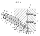
- the slot nozzle shown in FIG. 1, generally indicated by the reference numeral 10, has a nozzle body which consists of two plate-shaped parts 12 and 14 screwed together.
- nozzle body which consists of two plate-shaped parts 12 and 14 screwed together.
- two connecting screws 16 can be seen, the heads of which are countersunk in the surface of the part 14.
- the nozzle body is provided with holes in which heating cartridges are located. Such a bore is indicated by reference number 18. As a rule, several heating holes with heating cartridges are provided, in both parts 12, 14.
- a transverse channel 18 extends, which runs perpendicular to the sectional plane in FIG. 1, has a circular cross section and is connected to a melting device (not shown) which connects the usually solid or at least viscous, high-polymer material, in particular a hot melt adhesive based on polyurethane, melts and supplies the transverse channel 18 under pressure.
- shut-off valves 20 Several bores run at right angles to this transverse channel 18, are used in the shut-off valves 20; Although only one shut-off valve 20 is shown in the sectional view according to FIG. 1, several shut-off valves 20 are generally used, as can also be seen from FIG. 2, which indicates a total of four shut-off valves 20.
- Each shut-off valve 20 consists of a valve body 22 which is inserted into the bore of part 12 and has a bore in which a valve needle 24 can be pushed back and forth.
- the valve needle 24 is provided at its upper end with a piston 26 which is located in a piston chamber 28; the piston chamber has two compressed air connections, to which compressed air is alternately supplied in the direction of the arrows; as a result, the two surfaces of the piston 26 are acted upon alternately by compressed air, so that the piston 26 and thus the valve needle 24 are pushed back and forth pneumatically.
- valve body 22 ends somewhat above the transverse bore 18, a hole is formed surrounding the transverse bore 18, the bottom of which is covered with an exchangeable, plate-shaped seat 32 for the valve needle 24.
- the seat 32 has a bore 34 aligned with the bore for the valve needle 24 in the valve body 22, so that the tip of the valve needle 24 penetrates into the bore 34 in the seat 32 at one end of its stroke and closes it. This position is indicated in Figure 1.
- valve needle 24 clears the bore 34 in the seat 32 so that the liquid, highly polymeric thermoplastic material can flow out of the transverse bore 18 through the hole 19 into the bore 34 of the seat 32.
- an elongated spreading chamber 37 which extends almost over the entire length of the nozzle body from the two parts 12, 14 and is also aligned with the bores 36 so that the liquid, highly polymeric thermoplastic material is in a straight line from the hole 19th can flow into the spreading chamber 37 via the bore 34 in the seat 32 and the bore 36 in the part 12 and is thereby distributed uniformly over almost the entire length of the nozzle body 12, 14.
- the actual outlet slot 38 is arranged between the two end faces of the two parts 12, 14, which in the embodiment shown is formed by milling in the end face of the part 14.
- the slot can also be formed by a so-called “mask sheet”, that is to say a sheet metal piece clamped between the two parts 12, 14 with a recess forming the slot.
- the slot 38 extends in any case from the lower edge of the nozzle body 12, 14 up to the spreading chamber 37.
- the lower surfaces of the two parts 12, 14 are chamfered in the usual way; in addition, the lower edge of the left part 12 facing the exit slot 38 is slightly advanced (at 48), so that a tear-off edge is formed.
- the slot nozzle 10 receives the liquefied, high-polymer, thermoplastic material, in particular a hot melt adhesive based on polyurethane, under pressure from a liquefaction device via the transverse bore 18; from the transverse bore 18 the material reaches the various holes 19 and is under pressure there, since in the position shown in FIG. 1 the tip of the valve needle 24 is located in the outlet bore 34 of the seat 32 and the bore 36 is thus blocked.
- thermoplastic material in particular a hot melt adhesive based on polyurethane
- the piston 26 By acting on the surface of the piston 26 facing the valve body 22, the piston 26 is pneumatically displaced upward, so that the valve needle 24 moves upward and thus clears the bore 34, so that the liquid, highly polymeric thermoplastic material through the bore 34 in the seat 32, the bore 36 and the expansion chamber 37 can pass into the outlet slot 38 over the entire length.
- valve needle 24 By pressurizing the surface of the piston 26 facing away from the valve body 22 with compressed air, the valve needle 24 is moved downward again, thereby blocking the bore 34, so that the application of the high-polymer material is interrupted.
- valves four in the embodiment shown, can be provided, each of which supplies parts of the spreading chamber 37 with the liquid, high-polymer material.
- the spreading chamber 37 can also be located in the end face of the part 12; it is only essential that the liquid, highly polymeric material coming from the individual bores 36 is distributed uniformly over the entire length of the spreading chamber 37 and thus of the outlet slot 38.
- the material After leaving the transverse bore 18, the material flows in a straight line over a short distance from the hole 19 through the bores 34, 36 into the spreading chamber 37; the bending at the transition from the expansion chamber 37 into the slot 38 is only slight, since the bore 36 and slot 38 run at an angle of 120 ° to one another.
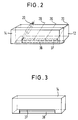
- FIG. 3 shows part 14 with the spreading chamber 37 and the cutout forming the outlet slot 38 in the end face of part 14.
- FIG. 2 shows a perspective side view of the nozzle body with the two parts 12, 14, four schematically indicated shut-off valves 20, the spreading chamber 37 and the outlet slot 38.
Landscapes
- Coating Apparatus (AREA)
- Nozzles (AREA)
- Percussion Or Vibration Massage (AREA)
- Lining Or Joining Of Plastics Or The Like (AREA)
Claims (12)
- Buse à fente pour l'application d'un matériau liquide à haut poids moléculaire, en particulier une colle fusible à base de polyuréthanne, comprenanta) un corps de buse,b) un canal d'amenée pour le matériau liquide dans le corps de buse,c) une soupape d'arrêt commandée,d) une chambre d'étalement faisant suite au canal d'amenée, ete) une fente de sortie raccordée à la chambre d'étalement,caractérisée en ce que
la soupape d'arrêt (20) est intégrée dans le corps de buse (12, 14) de telle façon que le canal d'amenée (34) est disposé à proximité immédiate de la chambre d'étalement (37), que le canal d'amenée (34) communique avec la chambre d'étalement (37) par l'intermédiaire d'une section rectiligne (36) placée dans le corps de buse (12, 14), la section (36) située dans le corps de buse (12, 14) présentant une faible longueur, et que le corps de buse (12, 14) présente un canal transversal (18) pour le matériau liquide à haut poids moléculaire, qui communique avec une chambre (19) disposée entre le corps de soupape (22) et le canal d'amenée (34). - Buse à fente selon la revendication 1, caractérisée en ce que la soupape d'arrêt comporte un corps de soupape (22) avec un pointeau de soupape (24) dont le mouvement alternatif peut être commandé pneumatiquement.
- Buse à fente selon l'une des revendications 1 ou 2, caractérisée en ce que le canal transversal (18) s'étend orthogonalement au canal d'amenée (34).
- Buse à fente selon l'une des revendications 1 à 3, caractérisée en ce que la distance entre la soupape d'arrêt (20) et l'entrée dans la chambre d'étalement (37) est d'au plus 50 mm, et en particulier d'au plus 25 mm.
- Buse à fente selon l'une des revendications 1 à 4, caractérisée en ce que le corps de buse (12, 14) comprend plusieurs canaux d'amenée (34) dont les sections droites (36) débouchent à chaque fois dans la chambre d'étalement (37).
- Buse à fente selon l'une des revendications 1 à 5, caractérisée en ce que la fente de sortie (38) forme avec le canal d'amenée (34) et respectivement sa section droite (36) un angle de plus de 90° et notamment de l'ordre de 110° à 150°.
- Buse à fente selon l'une des revendications 2 à 6, caractérisée en ce que le corps de soupape (20) est inséré dans un passage dans le corps de buse (12, 14), qui communique avec le canal transversal (18).
- Buse à fente selon la revendication 7, caractérisée en ce que dans le passage du corps de buse (12, 14) est prévu un siège (32) interchangeable pour le pointeau (24) de la soupape.
- Buse à fente selon l'une des revendications 1 à 8, caractérisée en ce que le corps de buse est constitué par deux éléments (12, 14) couplés, entre les surfaces d'appui desquels est conformée la fente de sortie (38).
- Buse à fente selon la revendication 9, caractérisée en ce que la fente de sortie (38) est constituée par une fraisure dans l'une des deux surfaces frontales des deux éléments (12, 14) ou par une tôle de masquage.
- Buse à fente selon l'une des revendications 9 ou 10, caractérisée en ce que la chambre d'étalement (37) est ménagée dans l'une des surfaces frontales des deux éléments (12, 14).
- Buse à fente selon l'une des revendications 9 à 11, caractérisée en ce que le passage pour la soupape d'arrêt (20) et la section (36) qui y fait suite sont disposés dans l'un des deux éléments (12, 14) du corps de buse.
Applications Claiming Priority (2)
| Application Number | Priority Date | Filing Date | Title |
|---|---|---|---|
| DE8812493U DE8812493U1 (de) | 1988-10-04 | 1988-10-04 | Schlitzdüse |
| DE8812493U | 1988-10-04 |
Publications (3)
| Publication Number | Publication Date |
|---|---|
| EP0366962A2 EP0366962A2 (fr) | 1990-05-09 |
| EP0366962A3 EP0366962A3 (en) | 1990-11-14 |
| EP0366962B1 true EP0366962B1 (fr) | 1995-03-01 |
Family
ID=6828548
Family Applications (1)
| Application Number | Title | Priority Date | Filing Date |
|---|---|---|---|
| EP89118397A Expired - Lifetime EP0366962B1 (fr) | 1988-10-04 | 1989-10-04 | Buse à fente |
Country Status (6)
| Country | Link |
|---|---|
| US (1) | US5056687A (fr) |
| EP (1) | EP0366962B1 (fr) |
| JP (1) | JP2752728B2 (fr) |
| AT (1) | ATE119080T1 (fr) |
| DE (2) | DE8812493U1 (fr) |
| ES (1) | ES2070875T3 (fr) |
Families Citing this family (10)
| Publication number | Priority date | Publication date | Assignee | Title |
|---|---|---|---|---|
| DE9108543U1 (de) * | 1991-07-11 | 1991-11-14 | Nordson Corp., Westlake, Ohio | Breitschlitzdüse zum Auftragen von Fluiden, insbesondere von Schmelzklebern |
| US5376414A (en) * | 1993-06-01 | 1994-12-27 | Sophia Systems Co., Ltd. | Expansion compensated precision extrusion method |
| US5622315A (en) * | 1995-03-14 | 1997-04-22 | Nordson Corporation | Adjustable slot goating die |
| JP2917127B2 (ja) * | 1996-07-12 | 1999-07-12 | 井上金属工業株式会社 | 塗布装置 |
| DE29622341U1 (de) * | 1996-12-23 | 1997-04-03 | Nordson Corp., Westlake, Ohio | Vorrichtung zum Auftragen von fließfähigem Material auf ein Substrat, insbesondere zum intermittierenden Auftragen von flüssigem Klebstoff |
| DE19714029C2 (de) * | 1997-04-04 | 1999-06-10 | Bargen Rudolf Von | Auftragskopf |
| DE19755625A1 (de) * | 1997-12-15 | 1999-07-01 | Jagenberg Papiertech Gmbh | Schlitzdüse zum Beschichten von Materialbahnen, insbesondere Papier- oder Kartonbahnen mit Pigmentstreichfarbe |
| DE19934641C1 (de) * | 1999-07-23 | 2000-10-12 | Itw Ind Gmbh | Vorrichtung zur dosierten Abgabe von strömenden Medien |
| DE10232984A1 (de) * | 2002-07-19 | 2004-02-05 | Steag Hamatech Ag | Düsenanordnung zum Aufbringen einer Flüssigkeit auf ein Substrat |
| CA2628504C (fr) | 2007-04-06 | 2015-05-26 | Ashley Stone | Dispositif de coulage |
Family Cites Families (10)
| Publication number | Priority date | Publication date | Assignee | Title |
|---|---|---|---|---|
| US3126574A (en) * | 1964-03-31 | Plow type glue gun | ||
| US3348520A (en) * | 1965-09-16 | 1967-10-24 | Lockwood Tech | Applicator system for hot melt adhesive and the like |
| GB1497661A (en) * | 1974-11-02 | 1978-01-12 | Molins Ltd | Devices for applying adhesives to a moving web |
| DE3223999A1 (de) * | 1981-07-02 | 1983-02-10 | Dynamelt (1981) Ltd., Daventry | Auftragskopf zum aufbringen einer beschichtung auf ein vorbeilaufendes band |
| US4613078A (en) * | 1984-04-09 | 1986-09-23 | Nordson Corporation | Quick replaceable nozzle assembly |
| US4667879A (en) * | 1985-08-21 | 1987-05-26 | Nordson Corporation | Thermoplastic material applicator having an adjustable slot nozzle |
| DE3541784C1 (de) * | 1985-11-26 | 1987-05-21 | Meltex Verbindungstechnik Gmbh | Vorrichtung zum Auftragen von fluessigem Klebstoff,insbesondere von Schmelzklber(hot melt) |
| US4735169A (en) * | 1986-09-03 | 1988-04-05 | Nordson Corporation | Adhesive applicator assembly |
| DE3635481C1 (en) * | 1986-10-18 | 1988-02-11 | Dittberner Gmbh | Nozzle head for the machine application of glue with a detachably fastened nozzle plate |
| US4774109A (en) * | 1987-07-21 | 1988-09-27 | Nordson Corporation | Method and apparatus for applying narrow, closely spaced beads of viscous liquid to a substrate |
-
1988
- 1988-10-04 DE DE8812493U patent/DE8812493U1/de not_active Expired - Lifetime
-
1989
- 1989-10-03 US US07/416,747 patent/US5056687A/en not_active Expired - Fee Related
- 1989-10-04 JP JP1261205A patent/JP2752728B2/ja not_active Expired - Fee Related
- 1989-10-04 DE DE58909056T patent/DE58909056D1/de not_active Expired - Fee Related
- 1989-10-04 EP EP89118397A patent/EP0366962B1/fr not_active Expired - Lifetime
- 1989-10-04 AT AT89118397T patent/ATE119080T1/de active
- 1989-10-04 ES ES89118397T patent/ES2070875T3/es not_active Expired - Lifetime
Also Published As
| Publication number | Publication date |
|---|---|
| ES2070875T3 (es) | 1995-06-16 |
| ATE119080T1 (de) | 1995-03-15 |
| DE58909056D1 (de) | 1995-04-06 |
| EP0366962A3 (en) | 1990-11-14 |
| DE8812493U1 (de) | 1990-02-01 |
| EP0366962A2 (fr) | 1990-05-09 |
| US5056687A (en) | 1991-10-15 |
| JPH02169065A (ja) | 1990-06-29 |
| JP2752728B2 (ja) | 1998-05-18 |
Similar Documents
| Publication | Publication Date | Title |
|---|---|---|
| DE69300548T2 (de) | Verbesserungen an und hinsichtlich des Aufbringens von Beschichtungen. | |
| DE69530243T2 (de) | Flüssigkeitsapplikator | |
| EP0577681B1 (fr) | Tuyere a fente de distribution de liquides | |
| EP0297268A2 (fr) | Dispositif pour appliquer des colles liquides sur un substrat | |
| EP4234094B1 (fr) | Buse d'application | |
| DE2815944C2 (de) | Mischkopf | |
| DE29622341U1 (de) | Vorrichtung zum Auftragen von fließfähigem Material auf ein Substrat, insbesondere zum intermittierenden Auftragen von flüssigem Klebstoff | |
| EP3957404B1 (fr) | Système d'application permettant de revêtir des composants et dispositif de revêtement | |
| DE3541784C1 (de) | Vorrichtung zum Auftragen von fluessigem Klebstoff,insbesondere von Schmelzklber(hot melt) | |
| EP0366962B1 (fr) | Buse à fente | |
| WO2012171976A1 (fr) | Support pour un dispositif de coupe | |
| DE3633343A1 (de) | Verfahren und vorrichtung zum herstellen eines kunststoff, insbesondere schaumstoff bildenden, fliessfaehigen reaktionsgemisches aus mindestens zwei fliessfaehigen reaktionskomponenten im durchlauf | |
| EP0744220B1 (fr) | Buse à fente | |
| DE3222992A1 (de) | Geraet zur abgabe eines geschaeumten klebstoffes o. dgl. materials | |
| DE102010011095A1 (de) | Düse zum Auftragen flüssiger Materialien | |
| DE102021109850A1 (de) | Dosiermodul | |
| DE69208402T2 (de) | Schlitzdüse zum Medienauftrag | |
| DE69903811T2 (de) | Verteilvorrichtung für ein fluid wie klebstoff | |
| EP3030379B1 (fr) | Griffe de serrage pour dispositif de serrage | |
| DE3852493T2 (de) | Herstellungsverfahren für eine Lochplatte für Brennstoff-Einspritzventile. | |
| DE112005000553B4 (de) | Stanzwerkzeug, Anordnung und Verfahren zum Stanzen einer schrägen Dosieröffnung durch eine Dosierscheibe für ein Kraftstoffeinspritzventil | |
| EP1729900A1 (fr) | Dispositif pour refroidir des toles et des feuillards | |
| DE202007007036U1 (de) | Mikrobreitenverstellbare Schlitzdüse | |
| EP0345666A2 (fr) | Tête de pulvérisation pour liquides | |
| DE9302107U1 (de) | Ventil |
Legal Events
| Date | Code | Title | Description |
|---|---|---|---|
| PUAI | Public reference made under article 153(3) epc to a published international application that has entered the european phase |
Free format text: ORIGINAL CODE: 0009012 |
|
| AK | Designated contracting states |
Kind code of ref document: A2 Designated state(s): AT BE CH DE ES FR GB GR IT LI LU NL SE |
|
| PUAL | Search report despatched |
Free format text: ORIGINAL CODE: 0009013 |
|
| AK | Designated contracting states |
Kind code of ref document: A3 Designated state(s): AT BE CH DE ES FR GB GR IT LI LU NL SE |
|
| 17P | Request for examination filed |
Effective date: 19910423 |
|
| 17Q | First examination report despatched |
Effective date: 19930115 |
|
| GRAA | (expected) grant |
Free format text: ORIGINAL CODE: 0009210 |
|
| ITF | It: translation for a ep patent filed | ||
| AK | Designated contracting states |
Kind code of ref document: B1 Designated state(s): AT BE CH DE ES FR GB GR IT LI LU NL SE |
|
| PG25 | Lapsed in a contracting state [announced via postgrant information from national office to epo] |
Ref country code: NL Free format text: LAPSE BECAUSE OF FAILURE TO SUBMIT A TRANSLATION OF THE DESCRIPTION OR TO PAY THE FEE WITHIN THE PRESCRIBED TIME-LIMIT Effective date: 19950301 Ref country code: GR Free format text: LAPSE BECAUSE OF FAILURE TO SUBMIT A TRANSLATION OF THE DESCRIPTION OR TO PAY THE FEE WITHIN THE PRESCRIBED TIME-LIMIT Effective date: 19950301 Ref country code: GB Effective date: 19950301 Ref country code: FR Effective date: 19950301 Ref country code: BE Effective date: 19950301 |
|
| REF | Corresponds to: |
Ref document number: 119080 Country of ref document: AT Date of ref document: 19950315 Kind code of ref document: T |
|
| REF | Corresponds to: |
Ref document number: 58909056 Country of ref document: DE Date of ref document: 19950406 |
|
| PG25 | Lapsed in a contracting state [announced via postgrant information from national office to epo] |
Ref country code: SE Effective date: 19950601 |
|
| REG | Reference to a national code |
Ref country code: ES Ref legal event code: FG2A Ref document number: 2070875 Country of ref document: ES Kind code of ref document: T3 |
|
| EN | Fr: translation not filed | ||
| NLV1 | Nl: lapsed or annulled due to failure to fulfill the requirements of art. 29p and 29m of the patents act | ||
| GBV | Gb: ep patent (uk) treated as always having been void in accordance with gb section 77(7)/1977 [no translation filed] |
Effective date: 19950301 |
|
| PG25 | Lapsed in a contracting state [announced via postgrant information from national office to epo] |
Ref country code: AT Effective date: 19951004 |
|
| PG25 | Lapsed in a contracting state [announced via postgrant information from national office to epo] |
Ref country code: LU Free format text: LAPSE BECAUSE OF NON-PAYMENT OF DUE FEES Effective date: 19951031 |
|
| PLBE | No opposition filed within time limit |
Free format text: ORIGINAL CODE: 0009261 |
|
| STAA | Information on the status of an ep patent application or granted ep patent |
Free format text: STATUS: NO OPPOSITION FILED WITHIN TIME LIMIT |
|
| 26N | No opposition filed | ||
| PGFP | Annual fee paid to national office [announced via postgrant information from national office to epo] |
Ref country code: ES Payment date: 20021018 Year of fee payment: 14 |
|
| PGFP | Annual fee paid to national office [announced via postgrant information from national office to epo] |
Ref country code: CH Payment date: 20021028 Year of fee payment: 14 |
|
| PGFP | Annual fee paid to national office [announced via postgrant information from national office to epo] |
Ref country code: DE Payment date: 20021129 Year of fee payment: 14 |
|
| PG25 | Lapsed in a contracting state [announced via postgrant information from national office to epo] |
Ref country code: ES Free format text: LAPSE BECAUSE OF NON-PAYMENT OF DUE FEES Effective date: 20031006 |
|
| PG25 | Lapsed in a contracting state [announced via postgrant information from national office to epo] |
Ref country code: LI Free format text: LAPSE BECAUSE OF NON-PAYMENT OF DUE FEES Effective date: 20031031 Ref country code: CH Free format text: LAPSE BECAUSE OF NON-PAYMENT OF DUE FEES Effective date: 20031031 |
|
| PG25 | Lapsed in a contracting state [announced via postgrant information from national office to epo] |
Ref country code: DE Free format text: LAPSE BECAUSE OF NON-PAYMENT OF DUE FEES Effective date: 20040501 |
|
| REG | Reference to a national code |
Ref country code: CH Ref legal event code: PL |
|
| REG | Reference to a national code |
Ref country code: ES Ref legal event code: FD2A Effective date: 20031006 |
|
| PG25 | Lapsed in a contracting state [announced via postgrant information from national office to epo] |
Ref country code: IT Free format text: LAPSE BECAUSE OF NON-PAYMENT OF DUE FEES;WARNING: LAPSES OF ITALIAN PATENTS WITH EFFECTIVE DATE BEFORE 2007 MAY HAVE OCCURRED AT ANY TIME BEFORE 2007. THE CORRECT EFFECTIVE DATE MAY BE DIFFERENT FROM THE ONE RECORDED. Effective date: 20051004 |