EP0300246B1 - Dispositif pour transporter des pastilles de combustible nucléaire d'une presse pour pastilles à une nacelle de frittage - Google Patents
Dispositif pour transporter des pastilles de combustible nucléaire d'une presse pour pastilles à une nacelle de frittage Download PDFInfo
- Publication number
- EP0300246B1 EP0300246B1 EP88110482A EP88110482A EP0300246B1 EP 0300246 B1 EP0300246 B1 EP 0300246B1 EP 88110482 A EP88110482 A EP 88110482A EP 88110482 A EP88110482 A EP 88110482A EP 0300246 B1 EP0300246 B1 EP 0300246B1
- Authority
- EP
- European Patent Office
- Prior art keywords
- pellet
- terminus
- brush
- chute
- pellets
- Prior art date
- Legal status (The legal status is an assumption and is not a legal conclusion. Google has not performed a legal analysis and makes no representation as to the accuracy of the status listed.)
- Expired - Lifetime
Links
Images

Classifications
-
- G—PHYSICS
- G21—NUCLEAR PHYSICS; NUCLEAR ENGINEERING
- G21C—NUCLEAR REACTORS
- G21C3/00—Reactor fuel elements and their assemblies; Selection of substances for use as reactor fuel elements
-
- G—PHYSICS
- G21—NUCLEAR PHYSICS; NUCLEAR ENGINEERING
- G21C—NUCLEAR REACTORS
- G21C21/00—Apparatus or processes specially adapted to the manufacture of reactors or parts thereof
-
- B—PERFORMING OPERATIONS; TRANSPORTING
- B65—CONVEYING; PACKING; STORING; HANDLING THIN OR FILAMENTARY MATERIAL
- B65G—TRANSPORT OR STORAGE DEVICES, e.g. CONVEYORS FOR LOADING OR TIPPING, SHOP CONVEYOR SYSTEMS OR PNEUMATIC TUBE CONVEYORS
- B65G11/00—Chutes
- B65G11/20—Auxiliary devices, e.g. for deflecting, controlling speed of, or agitating articles or solids
- B65G11/203—Auxiliary devices, e.g. for deflecting, controlling speed of, or agitating articles or solids for articles
-
- F—MECHANICAL ENGINEERING; LIGHTING; HEATING; WEAPONS; BLASTING
- F27—FURNACES; KILNS; OVENS; RETORTS
- F27D—DETAILS OR ACCESSORIES OF FURNACES, KILNS, OVENS OR RETORTS, IN SO FAR AS THEY ARE OF KINDS OCCURRING IN MORE THAN ONE KIND OF FURNACE
- F27D3/00—Charging; Discharging; Manipulation of charge
-
- F—MECHANICAL ENGINEERING; LIGHTING; HEATING; WEAPONS; BLASTING
- F27—FURNACES; KILNS; OVENS; RETORTS
- F27B—FURNACES, KILNS, OVENS OR RETORTS IN GENERAL; OPEN SINTERING OR LIKE APPARATUS
- F27B21/00—Open or uncovered sintering apparatus; Other heat-treatment apparatus of like construction
- F27B21/04—Sintering pots or sintering pans
-
- F—MECHANICAL ENGINEERING; LIGHTING; HEATING; WEAPONS; BLASTING
- F27—FURNACES; KILNS; OVENS; RETORTS
- F27D—DETAILS OR ACCESSORIES OF FURNACES, KILNS, OVENS OR RETORTS, IN SO FAR AS THEY ARE OF KINDS OCCURRING IN MORE THAN ONE KIND OF FURNACE
- F27D3/00—Charging; Discharging; Manipulation of charge
- F27D2003/0001—Positioning the charge
- F27D2003/0018—Positioning the charge comprising means to introduce or extract the charge in series of separate containers or zones
-
- F—MECHANICAL ENGINEERING; LIGHTING; HEATING; WEAPONS; BLASTING
- F27—FURNACES; KILNS; OVENS; RETORTS
- F27D—DETAILS OR ACCESSORIES OF FURNACES, KILNS, OVENS OR RETORTS, IN SO FAR AS THEY ARE OF KINDS OCCURRING IN MORE THAN ONE KIND OF FURNACE
- F27D3/00—Charging; Discharging; Manipulation of charge
- F27D3/10—Charging directly from hoppers or shoots
-
- F—MECHANICAL ENGINEERING; LIGHTING; HEATING; WEAPONS; BLASTING
- F27—FURNACES; KILNS; OVENS; RETORTS
- F27D—DETAILS OR ACCESSORIES OF FURNACES, KILNS, OVENS OR RETORTS, IN SO FAR AS THEY ARE OF KINDS OCCURRING IN MORE THAN ONE KIND OF FURNACE
- F27D5/00—Supports, screens or the like for the charge within the furnace
- F27D5/0068—Containers
-
- F—MECHANICAL ENGINEERING; LIGHTING; HEATING; WEAPONS; BLASTING
- F27—FURNACES; KILNS; OVENS; RETORTS
- F27M—INDEXING SCHEME RELATING TO ASPECTS OF THE CHARGES OR FURNACES, KILNS, OVENS OR RETORTS
- F27M2001/00—Composition, conformation or state of the charge
- F27M2001/18—Composition, conformation or state of the charge in the form of pellets
-
- Y—GENERAL TAGGING OF NEW TECHNOLOGICAL DEVELOPMENTS; GENERAL TAGGING OF CROSS-SECTIONAL TECHNOLOGIES SPANNING OVER SEVERAL SECTIONS OF THE IPC; TECHNICAL SUBJECTS COVERED BY FORMER USPC CROSS-REFERENCE ART COLLECTIONS [XRACs] AND DIGESTS
- Y02—TECHNOLOGIES OR APPLICATIONS FOR MITIGATION OR ADAPTATION AGAINST CLIMATE CHANGE
- Y02E—REDUCTION OF GREENHOUSE GAS [GHG] EMISSIONS, RELATED TO ENERGY GENERATION, TRANSMISSION OR DISTRIBUTION
- Y02E30/00—Energy generation of nuclear origin
- Y02E30/30—Nuclear fission reactors
-
- Y—GENERAL TAGGING OF NEW TECHNOLOGICAL DEVELOPMENTS; GENERAL TAGGING OF CROSS-SECTIONAL TECHNOLOGIES SPANNING OVER SEVERAL SECTIONS OF THE IPC; TECHNICAL SUBJECTS COVERED BY FORMER USPC CROSS-REFERENCE ART COLLECTIONS [XRACs] AND DIGESTS
- Y10—TECHNICAL SUBJECTS COVERED BY FORMER USPC
- Y10S—TECHNICAL SUBJECTS COVERED BY FORMER USPC CROSS-REFERENCE ART COLLECTIONS [XRACs] AND DIGESTS
- Y10S198/00—Conveyors: power-driven
- Y10S198/956—Impact plates
Definitions
- the present invention relates generally to an apparatus for loading newly made (green) friable nuclear fuel pellets into sintering boats from a pellet press.
- An operational step in the nuclear fuel fabrication process is the loading of friable nuclear fuel pellets, which have been ejected from the die table surface of a pellet press, into sintering boats (containers) in preparation for high temperature firing of the pellets in a sintering furnace.
- This operation requires careful handling of the pellets, because the pre-sintered pellets are easily crumbled.
- Typical nuclear fuel pellet loading devices are disclosed in U.S. Patent Nos. 4,332,120 and 4,566,835.
- the loader described in U.S. 4,332,120 employs a vertical chute which has a set of zig-zag inclined plates to guide the pellets into a boat which rests on a spring-biased platform.
- the loader described in U.S. 4,566,835 employs a horizontally disposed drum which receives a line of pellets into a vertically aligned lengthwise channel and which discharges the line of pellets into a boat when the drum rotates the channel to a below horizontal position.
- the invention resides in an apparatus for loading nuclear fuel pellets into a sintering boat from a pellet press which ejects newly made said pellets from a pellet press rotating die table surface, said apparatus characterized by: (a) an inclinable pellet chute having a generally straight centerline, an upper end disposable proximate said die table surface of said pellet press for receiving ejected said pellets, and a lower end disposable proximate said sintering boat for discharging the received said pellets; (b) a first member with a first resilient and generally planar surface having a first upper supported terminus and a flexible first lower free terminus, said first surface disposed such that a said pellet discharged from said chute will strike and reflect downwardly off said first surface; and (c) a second member with a second resilient and generally planar surface having a second upper supported terminus and a second lower free terminus, said second surface oriented generally parallel to the centerline of said chute and disposed such that a said pellet reflecting downwardly off said first surface will
- the chute and brush features together provide a soft-handling pellet transfer without motorized arrangements or a multiplicity of parts.
- the two-brush feature provides pellet deceleration through the pellet's alternate contact with the brushes followed by a further slowing of the pellet, before release, through the pellet's simultaneous contact with the brushes' free ends.
- Nuclear fuel pellets typically have a right circular cylindrical shape, a length of about 0.7 to 2.1 centimeters, and a diameter of about 0.6 to 1.3 centimeters. They usually are made from uranium dioxide powder which has been pressed into pellet form by a commercially available pellet press.
- the press normally has a rotating die table containing bores into which the powder is placed. Top and bottom punches compact the powder in the bore to fabricate the pellet. The top punch is withdrawn, and the bottom punch is raised to present a newly made pellet flush with the die table surface. The pellet is ejected from the die table surface when it encounters a stationary pellet-exiting shoe, which is part of the pellet press.
- Newly made pellets (sometimes called “green” pellets) are easily crumbled and therefor susceptible to damage during pellet handling, such as when they are loaded into sintering boats.
- the boats are containers which carry the pellets to a furnace for a pellet sintering operation.
- the pellets eventually are sealed in fuel rods which are grouped into fuel assemblies which are loaded into the core of a nuclear reactor.
- a liquid moderator/coolant such as water, is pumped through the core of the reactor and directed to pass along the fuel rods of the fuel assembly in order to extract heat generated therein by the fuel pellets for the production of useful work, such as the generation of electrical power.
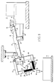
- the nuclear fuel pellet loading apparatus 10 of the invention along with a pellet press 12 and a sintering boat 14, is shown in Figure 1, while another embodiment of the pellet loading apparatus 10 is shown alone in Figure 2.
- a typical pellet press die table 16 is 45.7 centimeters in diameter, has sixteen pellet-forming stations (or bores, not shown), and rotates at seventeen revolutions per minute. Therefore, the newly made pellets 18 are ejected from the surface 20 of the die table 16 by a stationary pellet-exiting shoe (not shown) at a rate of 272 pellets per minute or close to 5 pellets per second.
- Typical pellet production rates for pellet presses range from 160 to 360 pellets per minute.
- the pellet loading apparatus 10 includes a pellet chute having a generally straight centerline.
- the chute is a stainless steel or polyvinyl chloride (PVC) tube 22 which is inclinable and has a polished inside surface so that pellets 22 may easily slide therethrough without damage.
- the tube's upper end 24 is disposable proximate the pellet press's die table surface 20 to receive the pellets 18 ejected therefrom.
- the tube 22 can include an upper attachment boss 26, near the bottom part of the tube's upper end 24, which is connected to a stationary portion of the pellet press 12 by a horizontal attachment bar 28.
- the tube's lower end 30 is disposable proximate the sintering boat 14 to discharge the received pellets.
- the tube 22 can include a lower attachment boss 32, near the top part of the tube's lower end 30, which is connected to a fixed vertical overhang by a vertical attachment bar 34.
- the tube 22 is inclined at an angle between about twenty to thirty degrees from the horizontal.
- the attachment of the tube may be adjustable for tube angle by, for example, making the horizontal and vertical attachment bars 28 and 34 telescoping to vary their lengths. Other tube positioning and angle varying arrangements are possible, as is known to those skilled in the art.
- the upper end 24 of the tube 22 includes an open top portion 36 to facilitate receipt of the pellets 18.
- the tube is 45 centimeters long with an inside diameter of 2.09 centimeters.
- a pellet 18 entering the upper end 24 of the tube 22 may do so with a motion that causes it to go partially up the side of the tube before settling into a straight line path along the bottom of the tube prior to being discharged from the tube's lower end 30.
- the tube's curved inside surface insures soft pellet handling during such motion, as can be appreciated by those skilled in the art.
- the pellet loader 10 also includes a first member 38 with a first resilient and generally planar surface 40, wherein the first surface 40 has a first upper supported terminus 42 and a flexible first lower free terminus 44, and the first surface 40 is disposed so that a pellet 18 discharged from the tube 22 will strike and reflect downwardly off the first surface 40.
- the first surface 40 is so disposed to reflect the pellet 18 downwardly in a generally vertical plane passing through the tube's centerline by being positioned generally perpendicular to said plane.
- the first surface 40 is oriented at an angle from about forty-five to about ninety degrees from the tube's centerline. Ninety degrees will accommodate slow pellet rates up to about three pellets per second, while the preferred forty-five degrees also will accommodate faster pellet rates up to about six pellets per second, all without inter-pellet contact.
- the first member 38 includes a first brush 46 (such as a nylon bristle paint brush) defining the first surface 40, and a rigid backing material 48 (such as a metal plate) attached to the first brush 46.
- the backing material 48 is not attached to the tip of the first brush 46 so that the tip (the first lower terminus 42 of the first surface 40) will be flexible.
- the pellet loader 10 additionally includes a second member 50 with a second resilient and generally planar surface 52, wherein the second surface 52 has a second upper supported terminus 54 and a (preferably flexible) second lower free terminus 56.
- the second surface 52 is oriented generally parallel to the tube's centerline and is disposed so that a pellet 18 reflected downwardly off the first surface 40 will strike and move downwardly along the second surface 52.
- the second surface 52 is so disposed to move the pellet 18 downwardly in a generally vertical plane passing through the tube's centerline by being positioned generally perpendicular to said plane.
- the second surface's lower terminus 56 is disposed with respect to the first surface's lower terminus 44 so that a pellet 18 moving downwardly along the second surface 52 will contact the first surface's lower terminus 44 before dropping off the second surface's lower terminus 56 into the sintering boat 14.
- the second member 50 includes a second brush 58 (such as a nylon bristle paint brush) defining the second surface 52, and a rigid backing material 60 (such as a metal plate) attached to the second brush 58.
- the backing material 60 is not attached to the tip of the second brush 58 so that the tip (the second lower terminus 56 of the second surface 52) will be flexible.
- the pellet-press-to-sintering-boat pellet loading apparatus 10 also includes a brush-holding fixture 62 attached to the tube 22 near its lower end 30.
- the fixture 62 includes a collar portion 64, coaxially surrounding the tube 22, and one or more set screws 66 to secure the collar portion 64 to the tube 22.
- the collar portion 64 includes a lower projection 68 to which the second brush's upper terminus 54 is attached and an upper projection 70 to which an arm member 72 of the fixture 62 is pivotally secured by a bolt 74.
- the first brush's upper terminus 42 is attached to the free end of the arm member 72.
- the set screw 66 allows the distance of the brushes 46 and 58, along an axis coincident with the tube's centerline, to be varied.
- the bolt 74 allows the angle of the first brush 46, from the tube's centerline, to be varied.
- the flexibility and separation distance of the tips of the brushes 46 and 58 may be chosen so that a pellet 18 moving downwardly along the second brush 58 will contact the tip of the first brush 46 (i.e., the first lower terminus 44 of the first surface 40) resulting in near-zero velocity when the pellet 18 drops off the second brush 58 (i.e., the second surface 52) into the sintering boat 14.
- the above-described elements of the pellet loading apparatus 10 work together to provide a gentle, controlled transfer of fragile, as-pressed, nuclear fuel pellets 18 from the press die table 16 to the sintering boat 14. It is clear that the dimensions of the elements, such as the length and slope of the tube 22, the size and tip separation distance of the brushes 46, 58, etc. are to be chosen to best meet the demands of the particular pellet press, pellet size, etc., as is within the purview of those skilled in the art.
Landscapes
- Engineering & Computer Science (AREA)
- Physics & Mathematics (AREA)
- General Engineering & Computer Science (AREA)
- Plasma & Fusion (AREA)
- High Energy & Nuclear Physics (AREA)
- Mechanical Engineering (AREA)
- Manufacturing & Machinery (AREA)
- Monitoring And Testing Of Nuclear Reactors (AREA)
- Chutes (AREA)
- Feeding Of Articles To Conveyors (AREA)
Claims (9)
- Dispositif (10) pour transporter des pastilles (18) de combustible nucléaire à une nacelle (14) de frittage à partir d'une presse (12) pour pastilles qui éjecte ces pastilles nouvellement fabriquées (18) de la surface (20) de la table tournante de matrice de la presse pour pastilles, ce dispositif comprenant :a) une goulotte inclinable (22) pour pastilles comportant un axe rectiligne dans son ensemble, une extrémité supérieure (24) disposée à proximité de cette surface (20) de la table de matrice de cette presse (12) pour pastilles pour recevoir ces pastilles éjectées (18), et une extrémité inférieure (30) disposée à proximité de cette nacelle (14) de frittage pour décharger ces pastilles reçues (18);b) un premier éléments (38) avec une première surface (40) élastique et plane dans son ensemble comportant une première extrémité supérieure supportée (42) et une première extrémité inférieure et flexible (44), cette première surface (40) étant placée de manière qu'une pastille (18) déchargée de cette goulotte (22) viendra heurter cette première surface (40) et sera renvoyée vers le bas à distance de celle-ci; etc) un deuxième élément (50) avec une deuxième surface (52) élastique et plane dans son ensemble comportant une deuxième extrémité supérieure supportée (54) et une deuxième extrémité inférieure libre (56), cette deuxième surface (52) étant orientée dans son ensemble parallèlement à l'axe de cette goulotte (22) et placée de manière qu'une telle pastille (18) renvoyée vers le bas à distance de cette première surface (40) viendra heurter cette deuxième surface (52) et se déplacera vers le bas le long de celle-ci, et cette deuxième extrémité inférieure (56) de cette deuxième surface (52) étant placée, par rapport à cette première extrémité inférieure (44) de cette première surface (38), de manière qu'une telle pastille (28) se déplaçant vers le bas le long de cette deuxième surface (52) viendra en contact avec cette première extrémité inférieure (44) de cette première surface (40) avant de tomber de cette deuxième extrémité inférieure (56) de cette deuxième surface (52) dans la nacelle (14) de frittage.
- Dispositif suivant la revendication 1, caractérisé en ce que cette goulotte est un tube (22).
- Dispositif suivant la revendication 2, caractérisé en ce que cette extrémité supérieure (24) de ce tube (22) comprend une partie supérieure ouverte.
- Dispositif suivant l'une quelconque des revendications 1 à 3, caractérisé en ce que cette première surface (40) est orientée pour former un angle compris entre environ quarante-cinq et environ quatre-vingt-dix degrés par rapport à l'axe de cette goulotte (22).
- Dispositif suivant l'une quelconque des revendications 1 à 3, caractérisé en ce que cette première surface (40) est orientée pour former un angle d'environ quarante-cinq degrés par rapport à l'axe de cette goulotte (22).
- Dispositif suivant la revendication 1, caractérisé en ce que cette deuxième extrémité inférieure (56) de cette deuxième surface (52) est flexible.
- Dispositif suivant l'une quelconque des revendications 1 à 6, caractérisé en ce que ce premier élément (38) comprend un premier pinceau (46) formant cette première surface (40) et en ce que ce deuxième élément (50) comprend un deuxième pinceau (58) formant cette deuxième surface (52).
- Dispositif suivant la revendication 7, caractérisé en ce que ce premier élément (38) comprend un support (48) en matériau rigide Fixé à ce premier pinceau (46) et en ce que ce deuxième élément (50) comprend un support (60) en matériau rigide fixé à ce deuxième pinceau (58).
- Dispositif suivant l'une ou l'autre des revendications 7 ou 8, caractérisé par une attache porte-pinceaux (62) fixée à cette goulotte (22) près de son extrémité inférieure (30), cette première extrémité supérieure (42) de ce premier pinceau (46) et cette deuxième extrémité supérieure (54) de ce deuxième pinceau (58) étant fixées à cette attache (62), et cette attache (62) étant réglable de manière à modifier l'écartement de ces pinceaux (46, 58) le long d'un axe coïncidant avec l'axe de cette goulotte (22) et réglable de manière à modifier l'angle de ce premier pinceau (46) par rapport à l'axe de cette goulotte (22).
Applications Claiming Priority (2)
| Application Number | Priority Date | Filing Date | Title |
|---|---|---|---|
| US07/077,347 US4807734A (en) | 1987-07-24 | 1987-07-24 | Pellet-press-to-sintering-boat nuclear fuel pellet loading apparatus |
| US77347 | 1987-07-24 |
Publications (3)
| Publication Number | Publication Date |
|---|---|
| EP0300246A2 EP0300246A2 (fr) | 1989-01-25 |
| EP0300246A3 EP0300246A3 (en) | 1989-09-27 |
| EP0300246B1 true EP0300246B1 (fr) | 1992-03-25 |
Family
ID=22137533
Family Applications (1)
| Application Number | Title | Priority Date | Filing Date |
|---|---|---|---|
| EP88110482A Expired - Lifetime EP0300246B1 (fr) | 1987-07-24 | 1988-06-30 | Dispositif pour transporter des pastilles de combustible nucléaire d'une presse pour pastilles à une nacelle de frittage |
Country Status (6)
| Country | Link |
|---|---|
| US (1) | US4807734A (fr) |
| EP (1) | EP0300246B1 (fr) |
| JP (1) | JPS6443799A (fr) |
| KR (1) | KR890002899A (fr) |
| DE (1) | DE3869505D1 (fr) |
| ES (1) | ES2030469T3 (fr) |
Families Citing this family (9)
| Publication number | Priority date | Publication date | Assignee | Title |
|---|---|---|---|---|
| US5048666A (en) * | 1989-03-02 | 1991-09-17 | Westinghouse Electric Corp. | Nuclear fuel pellet transfer escalator |
| US5897677A (en) * | 1997-07-24 | 1999-04-27 | Owens-Brockway Glass Contianer Inc. | Sampling of hot glassware in a glassware manufacturing system |
| FR2819481B1 (fr) * | 2001-01-17 | 2003-09-05 | Cogema | Dispositif et procede de transfert d'objets entre deux recipients ouverts |
| DE102004029359B4 (de) * | 2004-06-17 | 2006-08-03 | Siemens Ag | Vorrichtung zum Lagern eines Gegenstandes |
| FR2892556B1 (fr) * | 2005-10-24 | 2008-01-25 | Cogema | Dispositif de remplissage de nacelle avec des pastilles de combustible nucleaire et procede de remplissage mettant en oeuvre un tel dispositif |
| US7401695B2 (en) | 2006-06-07 | 2008-07-22 | The Gillette Company | Component control device, systems, and methods |
| CN108455256B (zh) * | 2018-01-19 | 2020-05-15 | 蔡海强 | 一种石油运输管道用运输安置设备 |
| CN110789911B (zh) * | 2019-08-20 | 2021-06-04 | 中建二局第一建筑工程有限公司 | 卸扣回收系统 |
| US20240158175A1 (en) * | 2021-03-16 | 2024-05-16 | Interroll Holding Ag | Conveying Arrangement |
Family Cites Families (17)
| Publication number | Priority date | Publication date | Assignee | Title |
|---|---|---|---|---|
| US1375988A (en) * | 1921-04-26 | walker | ||
| US1015937A (en) * | 1911-06-28 | 1912-01-30 | Delizio Brevetti | Life-saving apparatus. |
| US2896384A (en) * | 1958-03-20 | 1959-07-28 | Earl W Carlsen | Automatic box filler |
| US3066827A (en) * | 1960-01-11 | 1962-12-04 | Nat Vendors Inc | Article vending machine |
| US3034626A (en) * | 1961-02-14 | 1962-05-15 | Lamb Co F Jos | Brush controlled gravity feeds |
| US3187872A (en) * | 1963-02-18 | 1965-06-08 | Frederick L Hill | Tomato harvester |
| US3907128A (en) * | 1973-12-13 | 1975-09-23 | Ppg Industries Inc | Lead edge stop device |
| US3970218A (en) * | 1975-02-20 | 1976-07-20 | Lee Wing J | Cap selecting and feeding mechanism |
| US4122933A (en) * | 1977-04-04 | 1978-10-31 | Starzyk Eugene J | Feeder transfer chute |
| SE409627B (sv) * | 1978-01-24 | 1979-08-27 | Asea Atom Ab | Sett att anbringa brenslekutsar i kapslingsror vid framstellning av kernbrenslestavar jemte utrustning for genomforande av settet |
| US4332120A (en) * | 1980-03-05 | 1982-06-01 | Westinghouse Electric Corp. | Nuclear fuel pellet loading apparatus |
| US4340323A (en) * | 1980-10-30 | 1982-07-20 | Western Electric Co., Inc. | Decelerating and reorienting elongated magnetic articles |
| JPS59120013A (ja) * | 1982-12-28 | 1984-07-11 | 月星化成株式会社 | 青果物の緩速移送具 |
| US4573847A (en) * | 1983-08-12 | 1986-03-04 | Westinghouse Electric Corp. | Nuclear fuel rod channel tray loading system |
| US4566835A (en) * | 1983-09-28 | 1986-01-28 | Westinghouse Electric Corp. | Nuclear fuel pellet sintering boat loading system |
| US4642016A (en) * | 1984-08-03 | 1987-02-10 | Westinghouse Electric Corp. | Apparatus for unloading nuclear fuel pellets from a sintering boat |
| US4765453A (en) * | 1987-04-27 | 1988-08-23 | Westinghouse Electric Corp. | Pellet-press-to-sintering-boat nuclear fuel pellet loading system |
-
1987
- 1987-07-24 US US07/077,347 patent/US4807734A/en not_active Expired - Fee Related
-
1988
- 1988-06-30 ES ES198888110482T patent/ES2030469T3/es not_active Expired - Lifetime
- 1988-06-30 EP EP88110482A patent/EP0300246B1/fr not_active Expired - Lifetime
- 1988-06-30 DE DE8888110482T patent/DE3869505D1/de not_active Expired - Lifetime
- 1988-07-23 KR KR1019880009256A patent/KR890002899A/ko not_active Withdrawn
- 1988-07-25 JP JP63186682A patent/JPS6443799A/ja active Pending
Also Published As
| Publication number | Publication date |
|---|---|
| DE3869505D1 (de) | 1992-04-30 |
| US4807734A (en) | 1989-02-28 |
| EP0300246A2 (fr) | 1989-01-25 |
| EP0300246A3 (en) | 1989-09-27 |
| ES2030469T3 (es) | 1992-11-01 |
| KR890002899A (ko) | 1989-04-11 |
| JPS6443799A (en) | 1989-02-16 |
Similar Documents
| Publication | Publication Date | Title |
|---|---|---|
| EP0300246B1 (fr) | Dispositif pour transporter des pastilles de combustible nucléaire d'une presse pour pastilles à une nacelle de frittage | |
| US4765453A (en) | Pellet-press-to-sintering-boat nuclear fuel pellet loading system | |
| JP2683279B2 (ja) | ウェーハ移送装置 | |
| CN210794868U (zh) | 一种长棒料上料机 | |
| US4193502A (en) | Pellet dimension checker | |
| JPS6361637B2 (fr) | ||
| EP0372787A2 (fr) | Appareil pour le formage automatique | |
| US4566835A (en) | Nuclear fuel pellet sintering boat loading system | |
| US4954037A (en) | Method for aligning, lifting and tilting a container relative to a vertical aperture | |
| US4332120A (en) | Nuclear fuel pellet loading apparatus | |
| JPH0650350B2 (ja) | 自動組立装置 | |
| US4495146A (en) | Spherical nuclear fuel loading system | |
| CN113601041A (zh) | 一种自调节装夹对正打标机 | |
| EP0225114B1 (fr) | Système de nettoyage ultra-sonique des tubes pour des barres de combustible nucléaire ou des barres similaires | |
| US6854348B2 (en) | Method for counting foreign matter particles in vinyl chloride-based resin powder and apparatus system therefor | |
| CN210147267U (zh) | 一种激光切割机自动上料装置 | |
| CN218222276U (zh) | 一种入料装置及硫酸铁用搅拌桶 | |
| CN115816048B (zh) | 一种螺丝自动组装机构及组装设备 | |
| CN218567266U (zh) | 一种棒材检测设备 | |
| CN214669791U (zh) | 一种球形透镜分装装置 | |
| GB2154220A (en) | End plug orientation device | |
| JPS55119621A (en) | Mechanism for separating counted article | |
| CN214641246U (zh) | Kvm系统通信设备生产用触点焊接平台 | |
| CN220407526U (zh) | 一种激光打码设备 | |
| CN223372096U (zh) | 一种管状产品排料机构 |
Legal Events
| Date | Code | Title | Description |
|---|---|---|---|
| PUAI | Public reference made under article 153(3) epc to a published international application that has entered the european phase |
Free format text: ORIGINAL CODE: 0009012 |
|
| AK | Designated contracting states |
Kind code of ref document: A2 Designated state(s): BE DE ES FR GB IT SE |
|
| PUAL | Search report despatched |
Free format text: ORIGINAL CODE: 0009013 |
|
| AK | Designated contracting states |
Kind code of ref document: A3 Designated state(s): BE DE ES FR GB IT SE |
|
| 17P | Request for examination filed |
Effective date: 19900216 |
|
| 17Q | First examination report despatched |
Effective date: 19910812 |
|
| GRAA | (expected) grant |
Free format text: ORIGINAL CODE: 0009210 |
|
| ITF | It: translation for a ep patent filed | ||
| PGFP | Annual fee paid to national office [announced via postgrant information from national office to epo] |
Ref country code: FR Payment date: 19920319 Year of fee payment: 5 |
|
| AK | Designated contracting states |
Kind code of ref document: B1 Designated state(s): BE DE ES FR GB IT SE |
|
| ET | Fr: translation filed | ||
| PGFP | Annual fee paid to national office [announced via postgrant information from national office to epo] |
Ref country code: DE Payment date: 19920416 Year of fee payment: 5 |
|
| PGFP | Annual fee paid to national office [announced via postgrant information from national office to epo] |
Ref country code: GB Payment date: 19920421 Year of fee payment: 5 |
|
| REF | Corresponds to: |
Ref document number: 3869505 Country of ref document: DE Date of ref document: 19920430 |
|
| PGFP | Annual fee paid to national office [announced via postgrant information from national office to epo] |
Ref country code: BE Payment date: 19920625 Year of fee payment: 5 |
|
| PGFP | Annual fee paid to national office [announced via postgrant information from national office to epo] |
Ref country code: SE Payment date: 19920626 Year of fee payment: 5 |
|
| REG | Reference to a national code |
Ref country code: ES Ref legal event code: FG2A Ref document number: 2030469 Country of ref document: ES Kind code of ref document: T3 |
|
| PLBE | No opposition filed within time limit |
Free format text: ORIGINAL CODE: 0009261 |
|
| STAA | Information on the status of an ep patent application or granted ep patent |
Free format text: STATUS: NO OPPOSITION FILED WITHIN TIME LIMIT |
|
| 26N | No opposition filed | ||
| PG25 | Lapsed in a contracting state [announced via postgrant information from national office to epo] |
Ref country code: GB Effective date: 19930630 Ref country code: BE Effective date: 19930630 |
|
| PG25 | Lapsed in a contracting state [announced via postgrant information from national office to epo] |
Ref country code: SE Effective date: 19930701 |
|
| BERE | Be: lapsed |
Owner name: WESTINGHOUSE ELECTRIC CORP. Effective date: 19930630 |
|
| GBPC | Gb: european patent ceased through non-payment of renewal fee |
Effective date: 19930630 |
|
| PG25 | Lapsed in a contracting state [announced via postgrant information from national office to epo] |
Ref country code: FR Effective date: 19940228 |
|
| PG25 | Lapsed in a contracting state [announced via postgrant information from national office to epo] |
Ref country code: DE Effective date: 19940301 |
|
| REG | Reference to a national code |
Ref country code: FR Ref legal event code: ST |
|
| EUG | Se: european patent has lapsed |
Ref document number: 88110482.2 Effective date: 19940210 |
|
| PGFP | Annual fee paid to national office [announced via postgrant information from national office to epo] |
Ref country code: ES Payment date: 19960607 Year of fee payment: 9 |
|
| PG25 | Lapsed in a contracting state [announced via postgrant information from national office to epo] |
Ref country code: ES Free format text: LAPSE BECAUSE OF EXPIRATION OF PROTECTION Effective date: 19970701 |
|
| REG | Reference to a national code |
Ref country code: ES Ref legal event code: FD2A Effective date: 20000601 |
|
| PG25 | Lapsed in a contracting state [announced via postgrant information from national office to epo] |
Ref country code: IT Free format text: LAPSE BECAUSE OF NON-PAYMENT OF DUE FEES;WARNING: LAPSES OF ITALIAN PATENTS WITH EFFECTIVE DATE BEFORE 2007 MAY HAVE OCCURRED AT ANY TIME BEFORE 2007. THE CORRECT EFFECTIVE DATE MAY BE DIFFERENT FROM THE ONE RECORDED. Effective date: 20050630 |