EP0300734A2 - Procédé et dispositif pour la détermination de présence d'un enduit dans une bande de papier en mouvement - Google Patents
Procédé et dispositif pour la détermination de présence d'un enduit dans une bande de papier en mouvement Download PDFInfo
- Publication number
- EP0300734A2 EP0300734A2 EP88306597A EP88306597A EP0300734A2 EP 0300734 A2 EP0300734 A2 EP 0300734A2 EP 88306597 A EP88306597 A EP 88306597A EP 88306597 A EP88306597 A EP 88306597A EP 0300734 A2 EP0300734 A2 EP 0300734A2
- Authority
- EP
- European Patent Office
- Prior art keywords
- angle
- reflections
- web
- travelling web
- light
- Prior art date
- Legal status (The legal status is an assumption and is not a legal conclusion. Google has not performed a legal analysis and makes no representation as to the accuracy of the status listed.)
- Withdrawn
Links
Images

Classifications
-
- G—PHYSICS
- G01—MEASURING; TESTING
- G01N—INVESTIGATING OR ANALYSING MATERIALS BY DETERMINING THEIR CHEMICAL OR PHYSICAL PROPERTIES
- G01N21/00—Investigating or analysing materials by the use of optical means, i.e. using sub-millimetre waves, infrared, visible or ultraviolet light
- G01N21/17—Systems in which incident light is modified in accordance with the properties of the material investigated
- G01N21/55—Specular reflectivity
- G01N21/57—Measuring gloss
-
- A—HUMAN NECESSITIES
- A24—TOBACCO; CIGARS; CIGARETTES; SIMULATED SMOKING DEVICES; SMOKERS' REQUISITES
- A24C—MACHINES FOR MAKING CIGARS OR CIGARETTES
- A24C5/00—Making cigarettes; Making tipping materials for, or attaching filters or mouthpieces to, cigars or cigarettes
- A24C5/14—Machines of the continuous-rod type
- A24C5/31—Machines of the continuous-rod type with special arrangements coming into operation during starting, slowing-down or breakdown of the machine, e.g. for diverting or breaking the continuous rod
-
- A—HUMAN NECESSITIES
- A24—TOBACCO; CIGARS; CIGARETTES; SIMULATED SMOKING DEVICES; SMOKERS' REQUISITES
- A24C—MACHINES FOR MAKING CIGARS OR CIGARETTES
- A24C5/00—Making cigarettes; Making tipping materials for, or attaching filters or mouthpieces to, cigars or cigarettes
- A24C5/47—Attaching filters or mouthpieces to cigars or cigarettes, e.g. inserting filters into cigarettes or their mouthpieces
- A24C5/471—Attaching filters or mouthpieces to cigars or cigarettes, e.g. inserting filters into cigarettes or their mouthpieces by means of a connecting band
- A24C5/472—Applying adhesives to the connecting band
-
- G—PHYSICS
- G01—MEASURING; TESTING
- G01N—INVESTIGATING OR ANALYSING MATERIALS BY DETERMINING THEIR CHEMICAL OR PHYSICAL PROPERTIES
- G01N21/00—Investigating or analysing materials by the use of optical means, i.e. using sub-millimetre waves, infrared, visible or ultraviolet light
- G01N21/84—Systems specially adapted for particular applications
- G01N21/8422—Investigating thin films, e.g. matrix isolation method
- G01N2021/8427—Coatings
-
- G—PHYSICS
- G01—MEASURING; TESTING
- G01N—INVESTIGATING OR ANALYSING MATERIALS BY DETERMINING THEIR CHEMICAL OR PHYSICAL PROPERTIES
- G01N21/00—Investigating or analysing materials by the use of optical means, i.e. using sub-millimetre waves, infrared, visible or ultraviolet light
- G01N21/84—Systems specially adapted for particular applications
- G01N21/86—Investigating moving sheets
Definitions
- This invention relates to a method and apparatus for detecting the presence of a coating, for example an adhesive, on a travelling web.
- the invention relates to a method and apparatus that employs specular reflectance to determine the presence of a coating on cigarette tipping paper.
- the improper application of adhesive to cigarette tipping paper has been shown to cause severe performance defects in a cigarette.
- the cigarette rod can come apart from the filter while the smoker is pulling the cigarette from the pack, the fold-over of the tipping paper can cause defects in the visual appearance of the product, and insufficient adhesive can impair the performance of the cigarette by changing the draft/dilution characteristics of the cigarette.
- insufficient adhesive can cause a burning rod of tobacco to unexpectedly detach from the filter.
- U.S. Patent 2,141,052 discloses a system that measures the resistance of the paper as an adhesive is applied. The system disclosed, however, requires undesirable direct contact with the moving web.
- U.S. Patent 4,417,934 discloses a non-contact system that employs capacitive sensing to detect the presence of the adhesive. While this system avoids direct contact with the web, It is not suited to quantitatively measuring the width of the applied adhesive.
- An object of the present invention is to provide a method and apparatus for detecting the presence of a coating, for example an adhesive, on a travelling web.
- the invention provides an apparatus for detecting the presence of a coating material on a travelling web, said apparatus comprising:
- the invention provides a method of detecting the presence of a coating material on a surface of a travelling web, said method comprising the steps of:
- Specular or mirror-like reflection occurs when the angle of incidence of the incoming light and the angle of observation of the reflected light are equal or at least approximately the same. With any system of reflected light, there will be a specular component and a diffuse component which together constitute 100% of the reflected light. For shiny or smooth surfaces, e.g., the adhesive area on a paper web, the majority of incident light, as measured at an angle from the normal to the surface of the web, is specularly reflected at an approximately equal angle from the normal. However, when the surface of the object is not smooth, as for example, the non-adhesive area of the paper web, light is scattered at different angles and, therefore, the majority of reflected light is diffuse and the specular component is minimal. This occurs since the microscope contours of the web surface which are responsible for reflectance of the light are not necessarily aligned parallel to the overall web surface.
- the incident light on any given point of the web emanates from a number of point sources, and thus the angle of incidence must be considered as a range of angles from the web reflectance point to the plural point sources.
- a relatively rough surface such as the non-adhesive areas on the paper web are illuminated by a single point light source or by a light source having a relatively narrow range of angles of incident light, substantial amounts of reflected light can be observed at most angles of observation relative to the normal from the web surface, regardless of the angle or angles of incidence.
- the source of illumination is a point source or a diffuse source providing a relatively narrow range of angles of incident light
- the reflected light is viewed at an angle of observation equal to, or within the range of, the angle of illumination
- the optical gain from the smooth adhesive surface will be substantially higher than that of the rough web surface.
- the optical gain of the smooth adhesive surface will be substantially lower than the optical gain of the rough web surface.
- the invention can be employed for the purposes of differentiating between adhesive and paper surfaces at substantially any combination of illumination and observation angles between 0 and the limit of 90°.
- the angle of incidence of the incoming light and the angle of observation of reflected light are selected to be equal and to be between approximately 45° and 90° from the axis normal to the tipping paper.
- the light reflected from the adhesive will be of higher intensity than the light reflected from the rough web and thus, the adhesive will appear bright and the web dark (relative to the adhesive).
- the differences between the adhesive and the paper are most readily apparent if the angle of incidence of the incoming light and the angle of observation of the reflected light are equal with respect to the surface normal and are limited to between about 70° and about 90°.
- the paper appears white or bright and the adhesive appears dark (relatively) since observation of light reflected from the adhesive surface is minimized.
- At least the preferred embodiments of the invention provide significant advantages over prior art devices in detecting both the presence and width of one or more lines of adhesive on tipping paper.
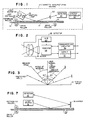
- a cigarette manufacturing machine 8 is shown in Fig. 1, wherein a web of tipping paper 10 for use in cigarettes is drawn past a patterning roller 12 that applies an adhesive layer 14 to the surface of the tipping paper 10.
- the light source 16 is comprised of a fluorescent aperture lamp 18 that provides diffused and spectrally stable light.
- a lamp controller 20 is provided to regulate the output of the lamp 18 and prevent ripple.
- the lamp controller 20 also over-drives the fluorescent aperture lamp 18 in order to obtain sufficient illumination for the detector 22.
- the lamp controller 20 and fluorescent aperture lamp are readily available components. (For example, MERCRON of Richardson, Texas is one company that produces lamp controllers for fluorescent aperture lamps suitable for use in the present invention).
- the detector 22 is a Honeywell HVS 256 High Accuracy Edge/Width Gauge detector.
- the HVS 256 detector is capable of performing high speed, non-contact, on-line inspection and gauging. As shown in Fig. 2, the HVS 256 detector has a CCD line scan sensor 24 having 256 pixels, an onboard computer 28, an A/D converter 29, and associated communications circuitry 30 and output circuitry 32.
- the HVS 256 detector can be programmed to detect up to eighteen edge positions and widths or centers (differences or midpoints between any two edges) along the pixel array that are calculated by the computer 28 and output in state, analog, or digital format.
- the HVS 256 detector is employed to measure parts that are placed in an object plane.
- the difference in reflectance between the background of the object plane and the part is detected as an edge transition.
- variations in surface reflectance produce brightness variations giving contrast (grey levels) which are converted to an electrical signal by the CCD line scan sensor 24, and transitions in the electrical signal are detected as the edges of the object by edge detection algorithms within the microprocessor of the HVS 256 detector.
- the HVS 256 detects the difference in the specular reflectance of the adhesive layer 14 and any uncoated areas of the tipping paper 10.
- the output of the detector 22 is supplied to a system controller 34 (Fig. 1) that controls the overall operation of the cigarette making machine 8.
- the illumination source 16 and the detector 22 are positioned in order to enhance the differences in the specular reflectance of uncoated areas of the tipping paper 10 and the adhesive layer 14 which has been applied to the paper.
- the angle of incidence for the illumination light and the angle of detection are preferably equal and selected to be between about 45° and 90° from an axis normal to the surface of the tipping paper 10 in order to optimize the ratio of intensity of observed specularly reflected light (from the adhesive surface) to the diffuse reflected light (from the web surface, e.g., see Fig. 3). Most preferably, the angle of incidence and the angle of detection are between 70° and 90° in order to achieve the best results.
- the adhesive layer 14 reflects diffuse light in a mirror-like manner and makes the adhesive layer 14 readily ascertainable from the surface of the tipping paper 10. Thus, the adhesive layer appears bright and the paper dark. It is essential that the illumination source 16 provide a uniform diffuse light in the across-machine direction, e.g., horizontally in Fig. 4, in order to prevent any bright or "hot" spots that might be generated from non-uniform point source dispersement of the light. A wide diffuse light source also reduces the criticality of the side to side alignment of the detector 22 and improves the accuracy of edge detection.
- the angle of incidence is selected to be less than 45° and preferably between 0° and 20° with a relatively large angle of observation of between 70° and 90°. More generally, the angle of incidence may range from 0°-40° with the angle of observation between 50°-90°. In both of these cases, the adhesive layer appears darker with the paper being brighter. In yet another embodiment, the angle of incidence may be large, on the order of 70°-90° (or more generally 50°-90°) with the angle of observation between 0°-20° (or more generally 0°-40°). In these latter cases as well, the paper appears brighter than the adhesive layer reflections. In other words, the adhesive layer appears darker than the paper since the angle of observation is substantially outside the range where one can observe the specularly reflected light from the adhesive layer.
- the web may be illuminated at an angle of incidence with a diffuse light source to produce first and second reflections.
- the first reflections are from a first portion of the surface of the web which is coated with the coating material, e.g., glue. These first reflections may be observed as specular reflections with light intensity I1, if the observation angle is substantially equal to the angle of incidence. These first reflections may also be observed with a light intensity I2 less than I1 if observed as non-specular reflections, namely, at angles not substantially equal to the incidence angle.
- the second reflections from the web come from a second portion of the web which is not coated.
- the received light has an intensity only varying between I3 min - I3 max, no coating is contained on the web. In such circumstances only "second reflections", i.e. those from the non-coated web, are detected.
- the received light intensity is higher (I1) or lower (I2) during part of the scan, then that part of the scan corresponds to the coated portion of the web which produces the "first reflections".
- the ratio of intensities of reflected light from the adhesive to reflected light from the web can be further enhanced by employing a polarizing filter between the web surface and the detector as shown by filter 40 in Figure 1. If the angles of illumination and observation are in a range near Brewster's Angle, i.e., 56.71° from the normal, the smooth adhesive tends to polarize the reflected light horizontally. Some small degree of polarization occurs in the light reflected from the web, but this will be substantially less than with the light reflected from adhesive.
- the intensity of light reflected from the adhesive is only minimally reduced; however, since the rough surfaces does not tend to promote significant polarization, the intensity of reflected light from the web surface is reduced nearly in half by the blocking action of the polarizing filter. As a result, contrast between the smooth adhesive and the rough filter web is increased substantially.
- the detector 22 detects the differences in the specular reflections from the adhesive layer 14 and any uncoated areas of the tipping paper 10, finds the edges, and then calculates the width of the adhesive layer 14. If the adhesive layer 14 is not present or out of a specified width range, the detector 22 provides an output signal to the system controller 34 indicating the out of range condition.
- the system controller 34 notes the location of the defect in the tipping paper 10 in memory and causes the rejection of cigarettes made from the defective tipping paper 10 at a downstream location of the cigarette manufacturing machine 8.
- the system controller 34 notes the position XO of the detection of an out of range condition and is programmed to reject the cigarettes made from the defective tipping paper 10 when they pass the rejection station at X1 positional units later.
- the operation of a system controller 34 to control a cigarette manufacturing machine 8 is well known within the cigarette manufacturing industry.
- Figs. 4a-6a Examples of typical adhesive patterns detected by the present invention are shown in Figs. 4a-6a and the associated output signal from the CCD line scanner 24 are shown in Figs. 4b-6b.
- the signal output shown in Figs. 4b-6b represent the output of the CCD line scanner 24 when it scans the tipping paper 10 along line A shown in Figs 4a-6a.
- the shaded areas of Figs. 4a-6a represent the adhesive layer 14 applied to the surface of the tipping paper 10. In all three cases the adhesive layer extends to the edge of the tipping paper 10.
- the areas B along the edge of the paper 10 are the most critical areas requiring the presence of adhesive. Preferably there is at least a 2 mm wide strip of adhesive within the 5 mm wide areas B.
- the Honeywell HVS 256 detector employed for the detector 22 can be programmed to "learn" what is considered a minimum condition by using Boolean logic to make decisions. For example, a sample tipping paper lacking adhesive in a 3 mm wide strip along the edge of the tipping paper is first placed in front of the detector 22. A switch is then activated causing the detector 22 to "remember" the limit, i.e., the signal pattern generated by the CCD line scanner 24 when viewing the sample tipping paper is stored by the computer 28. Alternately, the threshold values for determining the adhesive/paper boundary. In operation, the computer 28 continuously compares the signal generated from the CCD line scanner 24 with the remembered signal pattern. If an edge transition is not detected within the first 3 mm of the edge of the tipping paper an out of range signal is generated.
- the Honeywell HVS 256 detector utilized for detector 22 can also determine the distance between edge transitions.
- the overall width C of the adhesive layer can be determined, or the width of any intermediate areas where adhesive is not applied can be ascertained.
- the width of area D is of interest.
- the width of the tipping paper 10 shown in Figs. 4a-6a is used for two cigarettes during the manufacturing process.
- the tipping paper 10 is cut along the length of area D and it is therefore desirable that adhesive not be present in this area.
- the width of area D should preferably be maintained at about 1 mm.
- Other non-adhesive areas for example, areas E and F shown in Figs. 5a and 6a
- Other non-adhesive areas for example, areas E and F shown in Figs. 5a and 6a
- Other non-adhesive areas may be provided to regulate air flow in the cigarette filter.
- a folded optics arrangement as shown in Figure 7 may be employed.
- a mirror 36 is positioned at the appropriate angle of observation to provide the image from the adhesive layer 14 and tipping paper 10 to the detector 22.
- the detection of the specular reflections from the adhesive layer 14 and the tipping paper 10 permits accurate determination of the presence and width of the adhesive layer 14 not previously achieved in prior art devices.
- the diffuse light source employed in the present invention enhances the uniformity of specular reflections from the adhesive layer 14 and the tipping paper 10, allowing for easy detection of the edge transitions between the adhesive layer 14 and the surface of the tipping paper 10 by the detector 22.
- a 256 x 256 array scanner may be employed with a separate microprocessor performing the edge detection algorithms. In this case a single line of the array is utilized for data analysis.
- the invention provides a method and apparatus for detecting the boundary between two surfaces of a web, one surface being substantially smooth and the other being relatively rough; a method and apparatus that can detect the width of the adhesive applied to the travelling web; apparatus for detecting the presence of an adhesive on a travelling web having a structure that can easily be employed in a cigarette making machine; and a method and apparatus that optically enhances the differentiation of the adhesive from the tipping paper by detecting the differences in the specular reflectance of the adhesive and the paper.
Landscapes
- Physics & Mathematics (AREA)
- Health & Medical Sciences (AREA)
- Life Sciences & Earth Sciences (AREA)
- Chemical & Material Sciences (AREA)
- Analytical Chemistry (AREA)
- Biochemistry (AREA)
- General Health & Medical Sciences (AREA)
- General Physics & Mathematics (AREA)
- Immunology (AREA)
- Pathology (AREA)
- Investigating Materials By The Use Of Optical Means Adapted For Particular Applications (AREA)
Applications Claiming Priority (4)
| Application Number | Priority Date | Filing Date | Title |
|---|---|---|---|
| US7550687A | 1987-07-20 | 1987-07-20 | |
| US75506 | 1987-07-20 | ||
| US07/154,775 US4845374A (en) | 1987-07-20 | 1988-02-11 | Method and apparatus for detecting the deposition of an adhesive on a travelling web |
| US154775 | 1993-11-17 |
Publications (2)
| Publication Number | Publication Date |
|---|---|
| EP0300734A2 true EP0300734A2 (fr) | 1989-01-25 |
| EP0300734A3 EP0300734A3 (fr) | 1990-10-17 |
Family
ID=26756943
Family Applications (1)
| Application Number | Title | Priority Date | Filing Date |
|---|---|---|---|
| EP19880306597 Withdrawn EP0300734A3 (fr) | 1987-07-20 | 1988-07-19 | Procédé et dispositif pour la détermination de présence d'un enduit dans une bande de papier en mouvement |
Country Status (2)
| Country | Link |
|---|---|
| US (1) | US4845374A (fr) |
| EP (1) | EP0300734A3 (fr) |
Cited By (14)
| Publication number | Priority date | Publication date | Assignee | Title |
|---|---|---|---|---|
| DE3909990A1 (de) * | 1989-03-25 | 1990-09-27 | Bat Cigarettenfab Gmbh | Einrichtung zur erfassung ausreichender beleimung eines zu verklebenden papierstreifens |
| WO1999024819A1 (fr) * | 1997-11-10 | 1999-05-20 | Reinhard Loerke | Procede et dispositif permettant la detection de liquides sur un support solide, notamment mobile. |
| EP0906729A3 (fr) * | 1997-10-03 | 2000-09-13 | R.J. Reynolds Tobacco Company | Procédé et système de détection et de rejet des manques de colle sur du papier de cigarette |
| EP1050755A3 (fr) * | 1999-05-01 | 2001-12-19 | Sencon Europe Limited | Procédé et dispositif pour détection de revêtements |
| EP1258403A3 (fr) * | 2001-05-16 | 2004-03-03 | Nippon Sheet Glass Co., Ltd. | Capteur d'objet et appareil de contrôle d'essuie-glace utilisant ce capteur |
| EP1011351A4 (fr) * | 1997-07-11 | 2004-06-30 | Philip Morris Prod | Machine de fabrication de cigarettes comprenant un systeme de controle de bandes |
| US6758906B2 (en) | 2000-04-20 | 2004-07-06 | Hauni Mashinenbau Ag | Method of and apparatus for applying adhesive to webs of wrapping material |
| US7133126B2 (en) * | 2003-06-27 | 2006-11-07 | Delphi Technologies, Inc. | Method for the detection of coatings using emissivity and reflectivity |
| EP1849370A1 (fr) * | 2006-04-25 | 2007-10-31 | Hauni Maschinenbau AG | Surveillance de la position d'une bande de papier de recouvrement |
| WO2011063896A1 (fr) * | 2009-11-30 | 2011-06-03 | Hauni Maschinenbau Ag | Dispositif et procédé d'encollage pour machine de l'industrie du tabac |
| WO2017109482A1 (fr) * | 2015-12-23 | 2017-06-29 | British American Tobacco (Investments) Limited | Appareil pour détecter la présence d'adhésif |
| US10884401B2 (en) | 2016-05-06 | 2021-01-05 | Procemex Oy | Machine vision method and system for monitoring manufacturing processes |
| IT202000020788A1 (it) * | 2020-09-01 | 2022-03-01 | Gd Spa | Metodo e dispositivo di ispezione di sbozzati dell’industria del tabacco |
| WO2023280709A1 (fr) * | 2021-07-07 | 2023-01-12 | Focke & Co. (Gmbh & Co. Kg) | Procédé et dispositif pour détecter des parties d'un adhésif |
Families Citing this family (45)
| Publication number | Priority date | Publication date | Assignee | Title |
|---|---|---|---|---|
| US5081484A (en) * | 1987-03-01 | 1992-01-14 | Brother Kogyo Kabushiki Kaisha | Image recording medium and detecting device therefor |
| DE3733791A1 (de) * | 1987-10-06 | 1989-04-27 | Herbst Protechna Gmbh | Verfahren und vorrichtung zur optischen ueberwachung einer maschenware |
| FR2686697B1 (fr) * | 1992-01-27 | 1994-04-29 | Aerospatiale | Dispositif de detection de defauts dans des pieces bicouches, notamment dans des cellules solaires. |
| US5298346A (en) * | 1992-07-27 | 1994-03-29 | Motorola, Inc. | Battery identification system |
| US5414270A (en) * | 1993-05-14 | 1995-05-09 | R. J. Reynolds Tobacco Company | Method and apparatus for the automatic inspection of cigarette rods for spots and stains |
| US6058201A (en) * | 1995-05-04 | 2000-05-02 | Web Printing Controls Co., Inc. | Dynamic reflective density measuring and control system for a web printing press |
| US5966218A (en) * | 1997-07-11 | 1999-10-12 | Philip Morris Incorporated | Bobbin optical inspection system |
| US6198537B1 (en) * | 1997-07-11 | 2001-03-06 | Philip Morris Incorporated | Optical inspection system for the manufacture of banded cigarette paper |
| US6499402B1 (en) | 2000-05-17 | 2002-12-31 | Web Printing Controls Co., Inc. | System for dynamically monitoring and controlling a web printing press |
| DE10028000A1 (de) * | 2000-06-08 | 2001-12-13 | Hauni Maschinenbau Ag | Verfahren und Vorrichtung zum Zuführen eines abschnittweise perforierten Belagpapierstreifens für ventilierte Zigaretten |
| US7275548B2 (en) * | 2001-06-27 | 2007-10-02 | R.J. Reynolds Tobacco Company | Equipment for manufacturing cigarettes |
| US20040238136A1 (en) * | 2003-05-16 | 2004-12-02 | Pankaj Patel | Materials and methods for manufacturing cigarettes |
| DE10150272A1 (de) * | 2001-10-12 | 2003-04-17 | Hauni Maschinenbau Ag | Verfahren und Vorrichtung zur Überwachung von Leimbildern |
| DE10160235A1 (de) * | 2001-12-07 | 2003-06-26 | Hauni Maschinenbau Ag | Verfahren und Vorrichtung zur Erfassung einer Eigenschaft von Zigarettenpapier |
| DE10254880B4 (de) * | 2001-12-14 | 2009-06-10 | Heidelberger Druckmaschinen Ag | Verfahren zum Erkennen von Kanten von blattförmigen Materialien |
| US20040122547A1 (en) * | 2002-12-20 | 2004-06-24 | Seymour Sydney Keith | Equipment and methods for manufacturing cigarettes |
| US7281540B2 (en) * | 2002-12-20 | 2007-10-16 | R.J. Reynolds Tobacco Company | Equipment and methods for manufacturing cigarettes |
| US7234471B2 (en) * | 2003-10-09 | 2007-06-26 | R. J. Reynolds Tobacco Company | Cigarette and wrapping materials therefor |
| US7117871B2 (en) * | 2002-12-20 | 2006-10-10 | R.J. Reynolds Tobacco Company | Methods for manufacturing cigarettes |
| TWI240068B (en) * | 2003-01-21 | 2005-09-21 | Japan Tobacco Inc | Applied aroma chemical inspection device and tobacco manufacturing machine having same |
| US7047982B2 (en) * | 2003-05-16 | 2006-05-23 | R.J. Reynolds Tobacco Company | Method for registering pattern location on cigarette wrapping material |
| US20050087202A1 (en) * | 2003-10-28 | 2005-04-28 | R. J. Reynolds Tobacco Company | Apparatus for measuring a property of a cigarette paper wrapper and associated method |
| US20050115575A1 (en) * | 2003-12-01 | 2005-06-02 | Seymour Sydney K. | Cigarette paper testing apparatus and associated method |
| US20050181118A1 (en) * | 2004-02-12 | 2005-08-18 | Janssen Robert A. | Method for the precision saturation of substrates in preparation for digital printing, and the substrates produced therefrom |
| RU2294997C1 (ru) * | 2005-08-19 | 2007-03-10 | Михаил Александрович Великотный | Оптико-электронная система для настройки и диагностики технического состояния бумагоделательных машин (варианты) |
| US20070066475A1 (en) * | 2005-09-16 | 2007-03-22 | National Envelope Corporation | Envelope gum detection |
| CA2628090C (fr) * | 2005-11-07 | 2014-10-21 | Cardinal Cg Company | Procede et appareil destines a identifier des revetements photocatalytiques |
| US20080151252A1 (en) * | 2006-12-20 | 2008-06-26 | National Envelope Corporation | Seal gum thickness measurement |
| AT509306B1 (de) * | 2009-12-23 | 2015-02-15 | Tannpapier Gmbh | Verfahren zur herstellung einer bandförmigen kunststofffolie |
| IT1397555B1 (it) | 2010-01-14 | 2013-01-16 | Extrasolution S R L | Apparato e metodo per il posizionamento automatico di materiale in nastro, in particolare carta per sigarette, in macchine per il trattamento di detto materiale. |
| EP2551405B1 (fr) * | 2010-03-25 | 2015-12-16 | Japan Tobacco, Inc. | Machine de production d'une feuille continue de faible propension à l'allumage, procédé de production de celle-ci, et procédé de production d'un papier-filtre de faible propension à l'allumage utilisé dans des cigarettes |
| DE102010022273A1 (de) * | 2010-05-31 | 2011-12-01 | Sick Ag | Optoelektronischer Sensor zur Detektion von Objektkanten |
| US8768040B2 (en) * | 2011-01-14 | 2014-07-01 | Varian Semiconductor Equipment Associates, Inc. | Substrate identification and tracking through surface reflectance |
| US8666188B2 (en) * | 2011-03-23 | 2014-03-04 | Xerox Corporation | Identifying edges of web media using textural contrast between web media and backer roll |
| US9080987B2 (en) | 2011-05-26 | 2015-07-14 | Altria Client Services, Inc. | Oil soluble taggants |
| US9244017B2 (en) | 2011-05-26 | 2016-01-26 | Altria Client Services Llc | Oil detection process and apparatus |
| WO2013181286A1 (fr) | 2012-05-29 | 2013-12-05 | Altria Client Services Inc. | Procédé de détection d'huile |
| US9073091B2 (en) | 2013-03-15 | 2015-07-07 | Altria Client Services Inc. | On-line oil and foreign matter detection system and method |
| US9097668B2 (en) | 2013-03-15 | 2015-08-04 | Altria Client Services Inc. | Menthol detection on tobacco |
| EP2801786B1 (fr) | 2013-05-08 | 2019-01-02 | Sick AG | Capteur optoélectronique et procédé pour la détection de bords d'objets |
| WO2016077471A1 (fr) | 2014-11-11 | 2016-05-19 | Altria Client Services Inc. | Procédé de détection d'huile sur des produits du tabac et emballages |
| JP6498477B2 (ja) * | 2015-03-04 | 2019-04-10 | レンゴー株式会社 | ニス検査装置およびニス検査方法 |
| JP6630527B2 (ja) * | 2015-09-30 | 2020-01-15 | 日東電工株式会社 | 貫通孔を有する粘着フィルムの検査方法 |
| WO2017136404A1 (fr) | 2016-02-05 | 2017-08-10 | The Procter & Gamble Company | Procédé et appareil de détection de trous dans des substrats dans des lignes de conversion d'articles absorbants |
| US11397175B2 (en) | 2020-01-27 | 2022-07-26 | RJ. Reynolds Tobacco Company | Method and apparatus for the inspection of a paper web wound on a bobbin |
Family Cites Families (18)
| Publication number | Priority date | Publication date | Assignee | Title |
|---|---|---|---|---|
| US2142052A (en) * | 1934-11-22 | 1938-12-27 | Babcock & Wilcox Co | Press |
| US2141052A (en) * | 1937-05-11 | 1938-12-20 | Constantine S Stephano | Adhesive applicator |
| US2246501A (en) * | 1939-03-01 | 1941-06-24 | Champion Paper & Fibre Co | Glossmeter |
| US2797171A (en) * | 1951-04-25 | 1957-06-25 | Western Electric Co | Method of uniformly applying lacquer to paper strips |
| US2773412A (en) * | 1953-04-16 | 1956-12-11 | Huck Company | Electro-optical device for measuring thicknesses of coatings on materials |
| US3203547A (en) * | 1962-04-03 | 1965-08-31 | Illumitronic Systems Corp | Label inspection machine |
| GB1024796A (en) * | 1963-09-23 | 1966-04-06 | Metal Box Co Ltd | Improvements in or relating to apparatus for applying adhesive to carton blanks |
| US3330961A (en) * | 1964-04-15 | 1967-07-11 | Eastman Kodak Co | Photoelectric skip detector for use with a viscous layer applicator |
| JPS49141A (fr) * | 1972-04-21 | 1974-01-05 | ||
| AT334657B (de) * | 1975-01-24 | 1976-01-25 | Vianova Kunstharz Ag | Verbesserung zur messung des glanzvermogens von ebenen oberflachen |
| US4189335A (en) * | 1978-09-28 | 1980-02-19 | The Dow Chemical Company | Method for determining distribution of a coating composition on a carpet structure |
| US4250382A (en) * | 1979-08-14 | 1981-02-10 | Scott Paper Company | Coat detection method |
| US4323772A (en) * | 1980-03-06 | 1982-04-06 | R. J. Reynolds Tobacco Company | Bar code reader system |
| LU82230A1 (fr) * | 1980-03-07 | 1981-10-30 | Centre Rech Metallurgique | Procede de controle de la qualite des surfaces |
| GB2087544B (en) * | 1980-10-16 | 1985-05-22 | Nash Paul | Coating detector |
| US4417934A (en) * | 1980-11-05 | 1983-11-29 | Imperial Group Plc | Monitoring a deposit on a travelling web |
| US4525376A (en) * | 1982-03-16 | 1985-06-25 | Energy Conversion Devices, Inc. | Optical methods for controlling layer thickness |
| DE3242447C2 (de) * | 1982-11-16 | 1986-01-23 | Sophokles 8062 Markt Indersdorf Papaioannou | Photoelektrische Kontrollvorrichtung zur Qualitätskontrolle einer bewegten Materialbahn |
-
1988
- 1988-02-11 US US07/154,775 patent/US4845374A/en not_active Expired - Fee Related
- 1988-07-19 EP EP19880306597 patent/EP0300734A3/fr not_active Withdrawn
Cited By (17)
| Publication number | Priority date | Publication date | Assignee | Title |
|---|---|---|---|---|
| DE3909990A1 (de) * | 1989-03-25 | 1990-09-27 | Bat Cigarettenfab Gmbh | Einrichtung zur erfassung ausreichender beleimung eines zu verklebenden papierstreifens |
| CZ299693B6 (cs) * | 1997-07-11 | 2008-10-22 | Philip Morris Products Inc. | Optický systém pro kontrolu tkaniva materiálu proužkového papíru, stroj pro výrobu cigaret a zpusoboptické kontroly proužkového papíru |
| EP1011351A4 (fr) * | 1997-07-11 | 2004-06-30 | Philip Morris Prod | Machine de fabrication de cigarettes comprenant un systeme de controle de bandes |
| EP0906729A3 (fr) * | 1997-10-03 | 2000-09-13 | R.J. Reynolds Tobacco Company | Procédé et système de détection et de rejet des manques de colle sur du papier de cigarette |
| WO1999024819A1 (fr) * | 1997-11-10 | 1999-05-20 | Reinhard Loerke | Procede et dispositif permettant la detection de liquides sur un support solide, notamment mobile. |
| EP1050755A3 (fr) * | 1999-05-01 | 2001-12-19 | Sencon Europe Limited | Procédé et dispositif pour détection de revêtements |
| US6359277B1 (en) | 1999-05-01 | 2002-03-19 | Sencon Europe Limited | Method and apparatus for detecting coatings |
| US6758906B2 (en) | 2000-04-20 | 2004-07-06 | Hauni Mashinenbau Ag | Method of and apparatus for applying adhesive to webs of wrapping material |
| US7237557B2 (en) | 2000-04-20 | 2007-07-03 | Hauni Maschinenbau Ag | Method of and apparatus for applying adhesive to webs of wrapping material |
| EP1258403A3 (fr) * | 2001-05-16 | 2004-03-03 | Nippon Sheet Glass Co., Ltd. | Capteur d'objet et appareil de contrôle d'essuie-glace utilisant ce capteur |
| US7133126B2 (en) * | 2003-06-27 | 2006-11-07 | Delphi Technologies, Inc. | Method for the detection of coatings using emissivity and reflectivity |
| EP1849370A1 (fr) * | 2006-04-25 | 2007-10-31 | Hauni Maschinenbau AG | Surveillance de la position d'une bande de papier de recouvrement |
| WO2011063896A1 (fr) * | 2009-11-30 | 2011-06-03 | Hauni Maschinenbau Ag | Dispositif et procédé d'encollage pour machine de l'industrie du tabac |
| WO2017109482A1 (fr) * | 2015-12-23 | 2017-06-29 | British American Tobacco (Investments) Limited | Appareil pour détecter la présence d'adhésif |
| US10884401B2 (en) | 2016-05-06 | 2021-01-05 | Procemex Oy | Machine vision method and system for monitoring manufacturing processes |
| IT202000020788A1 (it) * | 2020-09-01 | 2022-03-01 | Gd Spa | Metodo e dispositivo di ispezione di sbozzati dell’industria del tabacco |
| WO2023280709A1 (fr) * | 2021-07-07 | 2023-01-12 | Focke & Co. (Gmbh & Co. Kg) | Procédé et dispositif pour détecter des parties d'un adhésif |
Also Published As
| Publication number | Publication date |
|---|---|
| US4845374A (en) | 1989-07-04 |
| EP0300734A3 (fr) | 1990-10-17 |
Similar Documents
| Publication | Publication Date | Title |
|---|---|---|
| US4845374A (en) | Method and apparatus for detecting the deposition of an adhesive on a travelling web | |
| US10267747B2 (en) | Surface defect inspecting device and method for steel sheets | |
| CN100448655C (zh) | 纺织帘子布层中接头搭接公差的自动控制和监视系统 | |
| US8194967B2 (en) | Article visual inspection apparatus | |
| US20090002686A1 (en) | Sheet Metal Oxide Detector | |
| JP2011053173A (ja) | 糸条の欠陥検出方法および欠陥検出装置 | |
| JP4158227B2 (ja) | 微小凹凸の検査方法および検査装置 | |
| JPH07218451A (ja) | 光学式鋼板表面検査装置 | |
| JPH06294749A (ja) | 板ガラスの欠点検査方法 | |
| JP2000097873A (ja) | 表面欠陥検査装置 | |
| KR100484812B1 (ko) | 이미지 센서를 이용한 표면 검사방법 및 검사장치 | |
| JP3932812B2 (ja) | 帯状金属処理面の検査装置 | |
| JP2002243648A (ja) | 帯状金属処理面の検査装置 | |
| JP2000161937A (ja) | 円柱状物体の表面検査装置 | |
| US6563575B1 (en) | Optical sensing system for detecting welds and defects in metal | |
| JP3293257B2 (ja) | 表面欠陥検査装置 | |
| JPH0581697U (ja) | 外観検査装置 | |
| JPS63218847A (ja) | 表面欠陥検査方法 | |
| JPH04178545A (ja) | 透明帯状体の検査方法及び装置 | |
| JPH08338815A (ja) | びん検査装置及びびん検査方法 | |
| JP3607163B2 (ja) | びん検査装置およびびん検査方法 | |
| JP2004354226A (ja) | 表面欠陥検査方法及び検査装置 | |
| JP7524717B2 (ja) | 検査装置 | |
| JPH09265536A (ja) | 外観検査装置および被検査部の照明方法 | |
| JPH0843048A (ja) | 物品の外観検査システムの検査精度の補償方法及びその装置 |
Legal Events
| Date | Code | Title | Description |
|---|---|---|---|
| PUAI | Public reference made under article 153(3) epc to a published international application that has entered the european phase |
Free format text: ORIGINAL CODE: 0009012 |
|
| AK | Designated contracting states |
Kind code of ref document: A2 Designated state(s): BE CH DE FR GB IT LI SE |
|
| PUAL | Search report despatched |
Free format text: ORIGINAL CODE: 0009013 |
|
| AK | Designated contracting states |
Kind code of ref document: A3 Designated state(s): BE CH DE FR GB IT LI SE |
|
| RHK1 | Main classification (correction) |
Ipc: G01N 21/89 |
|
| 17P | Request for examination filed |
Effective date: 19910131 |
|
| 17Q | First examination report despatched |
Effective date: 19921020 |
|
| STAA | Information on the status of an ep patent application or granted ep patent |
Free format text: STATUS: THE APPLICATION IS DEEMED TO BE WITHDRAWN |
|
| 18D | Application deemed to be withdrawn |
Effective date: 19931130 |