EP0300989B1 - Plattenventil für einen Kompressor - Google Patents
Plattenventil für einen Kompressor Download PDFInfo
- Publication number
- EP0300989B1 EP0300989B1 EP88890156A EP88890156A EP0300989B1 EP 0300989 B1 EP0300989 B1 EP 0300989B1 EP 88890156 A EP88890156 A EP 88890156A EP 88890156 A EP88890156 A EP 88890156A EP 0300989 B1 EP0300989 B1 EP 0300989B1
- Authority
- EP
- European Patent Office
- Prior art keywords
- plate
- valve
- damper
- ring
- rings
- Prior art date
- Legal status (The legal status is an assumption and is not a legal conclusion. Google has not performed a legal analysis and makes no representation as to the accuracy of the status listed.)
- Expired - Lifetime
Links
Images
Classifications
-
- F—MECHANICAL ENGINEERING; LIGHTING; HEATING; WEAPONS; BLASTING
- F04—POSITIVE - DISPLACEMENT MACHINES FOR LIQUIDS; PUMPS FOR LIQUIDS OR ELASTIC FLUIDS
- F04B—POSITIVE-DISPLACEMENT MACHINES FOR LIQUIDS; PUMPS
- F04B39/00—Component parts, details, or accessories, of pumps or pumping systems specially adapted for elastic fluids, not otherwise provided for in, or of interest apart from, groups F04B25/00 - F04B37/00
- F04B39/10—Adaptations or arrangements of distribution members
- F04B39/1053—Adaptations or arrangements of distribution members the members being Hoerbigen valves
-
- Y—GENERAL TAGGING OF NEW TECHNOLOGICAL DEVELOPMENTS; GENERAL TAGGING OF CROSS-SECTIONAL TECHNOLOGIES SPANNING OVER SEVERAL SECTIONS OF THE IPC; TECHNICAL SUBJECTS COVERED BY FORMER USPC CROSS-REFERENCE ART COLLECTIONS [XRACs] AND DIGESTS
- Y10—TECHNICAL SUBJECTS COVERED BY FORMER USPC
- Y10T—TECHNICAL SUBJECTS COVERED BY FORMER US CLASSIFICATION
- Y10T137/00—Fluid handling
- Y10T137/7722—Line condition change responsive valves
- Y10T137/7837—Direct response valves [i.e., check valve type]
- Y10T137/785—With retarder or dashpot
-
- Y—GENERAL TAGGING OF NEW TECHNOLOGICAL DEVELOPMENTS; GENERAL TAGGING OF CROSS-SECTIONAL TECHNOLOGIES SPANNING OVER SEVERAL SECTIONS OF THE IPC; TECHNICAL SUBJECTS COVERED BY FORMER USPC CROSS-REFERENCE ART COLLECTIONS [XRACs] AND DIGESTS
- Y10—TECHNICAL SUBJECTS COVERED BY FORMER USPC
- Y10T—TECHNICAL SUBJECTS COVERED BY FORMER US CLASSIFICATION
- Y10T137/00—Fluid handling
- Y10T137/7722—Line condition change responsive valves
- Y10T137/7837—Direct response valves [i.e., check valve type]
- Y10T137/7859—Single head, plural ports in parallel
- Y10T137/786—Concentric ports
-
- Y—GENERAL TAGGING OF NEW TECHNOLOGICAL DEVELOPMENTS; GENERAL TAGGING OF CROSS-SECTIONAL TECHNOLOGIES SPANNING OVER SEVERAL SECTIONS OF THE IPC; TECHNICAL SUBJECTS COVERED BY FORMER USPC CROSS-REFERENCE ART COLLECTIONS [XRACs] AND DIGESTS
- Y10—TECHNICAL SUBJECTS COVERED BY FORMER USPC
- Y10T—TECHNICAL SUBJECTS COVERED BY FORMER US CLASSIFICATION
- Y10T137/00—Fluid handling
- Y10T137/7722—Line condition change responsive valves
- Y10T137/7837—Direct response valves [i.e., check valve type]
- Y10T137/7859—Single head, plural ports in parallel
- Y10T137/7861—Annular head
- Y10T137/7862—Central post on seat
- Y10T137/7863—Stop
- Y10T137/7864—With guide
Definitions
- the invention relates to a plate valve for a compressor, with a valve seat, a catcher and a valve plate controlling through-channels provided in the valve seat, which consists of an outer ring and at least one inner ring, the rings being connected to one another by radial webs, and with a Springing for the valve plate, which consists of springs supported on the catcher, which only act on the outer ring, which is wider than the inner rings.
- Plate valves of this type are known in several versions.
- the valve plate is most stressed, which in many cases performs a wobbling movement due to uneven flows through the controlled medium, in which it first hits the catcher or the valve seat with its outer edge.
- a valve design is known in which a damper plate is provided which only extends over the inner plate rings of the valve plate.
- the outer ring of the valve plate is thus less stressed during the closing movement because it does not strike the damper plate and can swing out freely, so that its impact on the catcher is reduced.
- this design reduces the adhesive effect between the valve plate and the damper plate, because not only is the contact surface smaller, but the at least partially exposed outer ring of the valve plate can be caught by the flow and carried away. In this way, the stress on the valve plate during the closing movement is reduced, thereby increasing the service life of the entire compressor valve.
- a plate valve with the features mentioned at the outset is known from DE-C-480 326, FIGS. 4 and 5.
- the springs which act only on the outer ring lie there in the area of the radial webs between the plate rings on the valve plate, their contact surface being wider than the outer ring of the valve plate.
- the radial webs must therefore be made correspondingly wide in the circumferential direction, as a result of which the through slots of the valve plate are narrowed.
- the valve plate in the area of the springs supported on the catcher is also loaded by counter-springs arranged in the valve seat, the springing simultaneously forming a friction-free guidance of the valve plate during the lifting movement. Own measures for damping the impacts of the valve plate on the catcher and on the valve seat are not provided in this known valve design beyond the springing.
- the invention has a further improvement of the plate valves of this type for compressors and has set itself the task of further mitigating the surcharges of the valve plate, which is known to be the most stressed, both when opening and closing the valve, so that the The service life of the plate valve and its operational safety can be increased accordingly.
- the invention consists of a combination of several measures and is characterized in that the valve plate consists of a closure plate made of softer material, e.g. made of plastic, and a guide plate made of harder, flexible material, e.g. made of steel, is composed that the two plates lie on top of one another, the closure plate facing the valve seat and the guide plate facing the catcher, and that the outer ring of both plates is wider than the contact surface of the springs, springs also being arranged in the circumferential direction between the radial webs are.
- the valve plate consists of a closure plate made of softer material, e.g. made of plastic, and a guide plate made of harder, flexible material, e.g. made of steel, is composed that the two plates lie on top of one another, the closure plate facing the valve seat and the guide plate facing the catcher, and that the outer ring of both plates is wider than the contact surface of the springs, springs also being arranged in the circumferential direction between the radial webs are.
- GB-A-1 500 391 already describes a valve for gas compressors in which plastic is used to dampen the impacts on the valve plate and in this way to reduce wear and noise.
- plastic is used to dampen the impacts on the valve plate and in this way to reduce wear and noise.
- both the impact surfaces on the valve seat and on the catcher and the surfaces of the valve plate interacting therewith are covered with an elastic material such as plastic.
- These plastic coatings are made thinner than the metallic valve plate itself and accordingly not very effective and not very wear-resistant.
- the production of the coatings on practically four different surfaces is associated with corresponding effort.
- the closure plate which is made of softer material, preferably plastic, and which is also considerably thicker than the thinner guide plate resting on it, ensures a perfect seal and at the same time effectively mitigates the impacts the valve plate on the valve seat.
- the guide plate made of harder material, such as steel, supports the softer closure plate and gives it the required strength and stability. It also serves for the uniform transmission of the spring forces to the individual rings of the closure plate.
- the wide outer ring reinforces the valve plate in the most stressed area and also allows the springs to be distributed over its entire circumference. This concentration of the springs on the outer edge of the valve plate greatly improves their parallel guidance during the stroke movement, so that the tendency to wobble is largely eliminated.
- a damper plate is provided, which is loosely inserted between the catcher and the guide plate and only extends over the area of the inner rings of the guide plate and the associated closure plate, although there is no separate mounting or fastening of the damper plate in the valve , the damper plate softens the impact of the valve plate on the catcher and makes it easier to detach the valve plate from the catcher during the closing movement.
- the damper effect is particularly advantageous if the damper plate consists of concentric rings which are connected to one another by radial webs, and if at least one ring section between two adjacent radial webs is bent out of the plate plane in a wave shape. This design causes an additional resilient catch of the valve plate during the opening movement.
- the ring sections of the damper plate are narrower than the rings of the valve plate and / or the rings of the stop surface of the catcher, which are axially aligned with them, then the area over which the adjacent plates rest on one another when the valve is open , reduced accordingly.
- This also reduces the adhesive force between the surfaces lying on top of one another, so that even if an oil film occurs on the surfaces, a disadvantageous adhesive force which would cause the valve to close late is avoided.
- the same advantages can be achieved or, when used together, can be increased by cutting out part of the ring sections of the damper plate and passing through the webs in the cut-out areas until the ring after next. The reduction in the contact area results from the absence of one or more rings of the damper plate.
- a further embodiment of the invention provides that at least two ring sections are bent out in a wave shape in different directions from the plane of the damper plate. This results in an increase in the spring action and an approximately even distribution over the surface of the damper plate.
- the total thickness of the damper plate with bent-out ring sections should be smaller in the relaxed state than the free distance between the catcher and the guide plate in the region of the damper plate.
- the spring force of the ring sections bent out of the damper plate acts only during the opening movement of the valve plate to cushion the impact, but avoids an increase in the closing force itself and thus a delay in the opening movement.
- the catcher can have a flat stop surface against which the damper plate rests when the valve is open. This creates a gradation on the outer edge of the damper plate, so that the outer ring of the valve plate has a stroke greater by the thickness of the damper plate and can swing out a little before striking the catcher.
- the depth of the recess in the stop surface of the catcher is suitably smaller than the thickness of the damper plate in the unloaded state, so that the resilient ring sections come into full effect.
- the flow of the controlled medium through the valve can be improved in the invention in that both in the closure plate and in the guide plate the free slots between the outer ring and the subsequent inner ring are wider than the remaining slots between the inner rings.
- This measure takes into account the wider design of the outer ring and brings about an adaptation of the area of the individual slots available for the flow to the flow quantity occurring in the respective area.
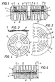
- FIG. 1 shows an axial central section through a first embodiment of a plate valve according to the invention for a compressor
- FIG. 2 shows a partial section of the valve plate in a top view
- FIG. 3 shows a side view
- FIG. 4 shows a top view of the damper plate
- FIG. 5 shows a axial middle section through a further embodiment of the plate valve according to the invention, only the left valve half being shown.
- the plate valve consists of a valve seat 1 and a catcher 2 which is fastened on the valve seat 1 with the aid of a screw 3. With its outer edge 4, the catcher 2 rests on the valve seat 1, a spacer ring 5 is arranged in the center between the valve seat 1 and the catcher 2.
- the valve plate 7 lies in an intermediate space 8 between the valve seat 1 and the catcher 2 and is guided with its inner edge on the outer surface of the spacer ring 5.
- the catcher 2 has on its side facing the valve plate 7 a stop surface 9, on which a damper plate 10 rests. Outflow openings for the controlled medium are provided in the catcher.
- the valve plate 7 is composed of a closure plate 14 and a guide plate 15.
- the closure plate 14 faces the valve seat 1 and is made of a softer material than the guide plate 13, e.g. made of a plastic material, and controls the through channels 6 of the valve seat 1.
- Steel guide plate 15 faces the catcher 2 and has the task of supporting and stabilizing the closure plate 14, which is made of less solid material.
- the guide plate 15 distributes the spring force exerted by the springs 13 on the valve plate 7 over the entire surface of the valve plate 7.
- the closure plate 14 and the guide plate 15 have the same plan and lie on one another. At most, they can be connected to each other at individual points or over their entire area, e.g. 2 shows that the valve plate 7, that is to say both the closure plate 14 and the guide plate 15, consists of an outer ring 16 and a plurality of inner rings 17 which are connected to one another by radial webs 18. There are slots 19 between the individual rings 16, 17 for the passage of the controlled medium.
- the outer ring 16 of the closure plate 14 and the guide plate 15 is substantially wider than the inner rings 17.
- the slots 19 between the outer ring 16 and the adjoining inner ring 17 are also wider than the remaining slots 19 between the inner rings 17.
- the damper plate 10 This also consists of concentric rings 20 which are connected to one another by radial webs 21. Some ring sections between the webs 21 are bent out of the plate plane in a wave shape. From Fig. 3 it can be seen that the ring portions 22 of the outermost ring 20 are bent down and the ring portions 23 of the middle ring 20 are bent upwards. The innermost ring 20 is flat. The bends of the ring sections 22 and 23 are shown somewhat enlarged in FIG. 3. Any other deformation of the damper plate 10 is also possible within the scope of the invention, which results in a spring effect of the damper plate 10 in a certain range.
- the ring sections 23 are narrower than the ring sections 22 and also narrower than the innermost ring 20 of the damper plate 10 Catcher 2, With this measure, the contact area between the valve plate 7 and the damper plate 10 is reduced, which also reduces the adhesive force between the two plates, which occurs due to adhesive action if an oil film between the two plates 7 and 10 or the catcher 2 4, dashed lines 25 also indicate that the radial webs 21 can pass between the outer and the inner ring 20 of the damper plate 10, the middle ring 20 with the ring sections 23 can therefore be omitted entirely.
- This design also reduces the contact surface between the damper plate 10 and the catcher 2 or the valve plate 7, so that the two plates can easily detach from the stop surface 9 of the catcher 2 and from one another when the valve is closed. All rings 20 of the damper plate 10 can also be narrower than the rings of the valve plate 7 or catcher 2.
- the total thickness of the damper plate 10 with bent-out ring sections 22, 23 is smaller in the relaxed state than the free distance in the region of the damper plate 10 between the catcher 2 and the guide plate 15 in the space designated by 8 in FIG. 1.
- the damper plate 10 is loosely inserted between the catcher 2 and the guide plate 15 so that it rests on the valve plate 7 when the valve is closed and follows its movements. It can also be seen that the damper plate 10 extends in the radial direction only over the inner rings 17 of the valve plate 7, the wider outer ring 16 being loaded only by the springs 13. But it is also possible to clamp the damper plate 10 in the valve or with its own guide, e.g. with flexible handlebars.
- valve plate 7 Due to the action of the springs 13 distributed over the circumference of the valve plate 7, stabilization and good parallel guidance of the valve plate 7 is achieved during the lifting movement. The tendency of the valve plate 7 to wobble and disadvantageous oblique impacts of the plate edge on the valve seat 1 or the catcher 2 are largely avoided.
- a recess 24 is provided for the damper plate 10 in the stop surface 9 of the catcher 2.
- This makes it possible to arrange the damper plate 10 completely or partially sunk in the catcher 2.
- the embodiment shown in FIG. 5 differs in that the stop surface 9 of the catcher 2 is flat, so that the damper plate 10 forms a small gradation in the region of the outer ring 16 of the valve plate 7. This has the effect that the outer ring 16 can perform a somewhat larger stroke movement than the inner rings 17, whereby its impacts on the catcher 2 are damped.
- the valve plate 7 also consists of a closure plate 14 and a guide plate 15, the outer ring 16 being wider than the inner rings 17.
- the slot 19 between the outer ring 16 and the inner rings 17 is also wider than the other slots 19 between the inner rings 17, the outflow openings 11 in the catcher 2 being somewhat wider in this area than in the central area of the plate valve.
Landscapes
- Engineering & Computer Science (AREA)
- Mechanical Engineering (AREA)
- General Engineering & Computer Science (AREA)
- Check Valves (AREA)
- Compressor (AREA)
Description
- Die Erfindung bezieht sich auf ein Plattenventil für einen Kompressor, mit einem Ventilsitz, einem Fänger und einer im Ventilsitz vorgesehene Durchgangskanäle steuernden Ventilplatte, die aus einem Außenring und aus wenigstens einem Innenring besteht, wobei die Ringe durch radiale Stege miteinander verbunden sind, und mit einer Befederung für die Ventilplatte, die aus am Fänger abgestützten Federn besteht, die nur auf den Außenring wirken, der breiter ist als die Innenringe.
- Plattenventile dieser Art sind in mehreren Ausführungen bekannt. Die zwischen dem Ventilsitz und dem Fänger angeordneten Platten, die im Hubtakt des Kompressors bewegt werden und mit verhältnismäßig großen Geschwindigkeiten auf dem Fänger und auf dem Ventilsitz aufschlagen, sind hohen Beanspruchungen ausgesetzt. Am stärksten beansprucht ist die Ventilplatte, die in vielen Fällen aufgrund von ungleichmäßigen Anströmungen durch das gesteuerte Medium eine Taumelbewegung ausführt, bei der sie zuerst mit ihrem Außenrand auf dem Fänger bzw. auf dem Ventilsitz auftrifft.
- Es ist bekannt, durch die Anordnung von Dämpferplatten zwischen der Ventilplatte und dem Fänger die Aufschläge der Ventilplatte beim Öffnen des Ventils zu mildern. Diese Maßnahme allein ist aber nicht immer ausreichend. Beispielsweise bildet sich bei mit Öl geschmierten Kompressoren ein Ölfilm auf den Platten, der bewirkt, daß die Platten aneinander und am Fänger kleben. Dadurch wird der Schließvorgang der Ventilplatte verspätet eingeleitet, was zur Folge hat, daß die Schließbewegung durch zurückströmendes Medium beschleunigt wird, wodurch die Aufschläge der Ventilplatte auf dem Ventilsitz verstärkt werden. Außerdem kommt es durch verspätetes Schließen der Ventile zu einer Verringerung der Förderleistung des Kompressors.
- Aus der US-A-3 703 912 ist eine Ventilausführung bekannt, bei der eine Dämpferplatte vorgesehen ist, die nur über die inneren Plattenringe der Ventilplatte reicht. Der Außenring der Ventilplatte wird dadurch bei der Schließbewegung weniger beansprucht, weil er nicht auf die Dämpferplatte auftrifft und frei ausschwingen kann, so daß sein Aufschlagen auf den Fänger gemildert wird. Außerdem wird durch diese Ausbildung die Klebewirkung zwischen der Ventilplatte und der Dämpferplatte verringert, weil nicht nur die Auflagefläche kleiner ist, sondern der zumindest teilweise freiliegende Außenring der Ventilplatte von der Strömung erfaßt und mitgerissen werden kann. Auf diese Weise wird die Beanspruchung der Ventilplatte bei der Schließbewegung verringert und dadurch die Lebensdauer des gesamten Kompressorventils vergrößert.
- Ein Plattenventil mit den eingangs angeführten Merkmalen ist aus der DE-C-480 326, Fig. 4 und 5, bekannt. Die nur auf den Außenring wirkenden Federn liegen dort im Bereich der radialen Stege zwischen den Plattenringen auf der Ventilplatte auf, wobei ihre Auflagefläche breiter ist als der Außenring der Ventilplatte. Die radialen Stege müssen deshalb in Umfangsrichtung entsprechend breit ausgebildet sein, wodurch die Durchgangsschlitze der Ventilplatte eingeengt werden. Außerdem ist die Ventilplatte im Bereich der am Fänger abgestützten Federn auch durch im Ventilsitz angeordnete Gegenfedern belastet, wobei die Befederung zugleich eine reibungsfreie Führung der Ventilplatte während der Hubbewegung bildet. Eigene Maßnahmen zum Dämpfen der Aufschläge der Ventilplatte auf dem Fänger und auf dem Ventilsitz sind bei dieser bekannten Ventilausbildung über die Befederung hinaus nicht vorgesehen.
- Die Erfindung hat eine weitere Verbesserung der Plattenventile dieser Bauart für Kompressoren zum Gegenstand und hat sich die Aufgabe gestellt, die Aufschläge der Ventilplatte, die bekanntlich am höchsten beansprucht ist, sowohl beim Öffnen als auch beim Schließen des Ventils weiter zu-mildern, so daß die Lebensdauer des Plattenventils und dessen Betriebssicherheit entsprechend vergrößert werden.
- Die Erfindung besteht aus einer Kombination mehrerer Maßnahmen und ist dadurch gekennzeichnet, daß die Ventilplatte aus einer Verschlußplatte aus weicherem Werkstoff, z.B. aus Kunststoff, und einer Führungsplatte aus härterem, flexiblem Werkstoff, z.B. aus Stahl, zusammengesetzt ist, daß die beiden Platten aufeinander aufliegen, wobei die Verschlußplatte dem Ventilsitz und die Führungsplatte dem Fänger zugewendet ist, und daß der Außenring beider Platten breiter ist als die Auflagefläche der Federn, wobei in Umfangsrichtung auch zwischen den radialen Stegen Federn angeordnet sind.
- In der GB-A-1 500 391 ist zwar schon ein Ventil für Gaskompressoren beschrieben, bei dem Kunststoff verwendet wird, um die Aufschläge der Ventilplatte zu dämpfen und auf diese Weise den Verschleiß und die Lärmentwicklung zu mildern. Zur Erreichung dieses Ziels sind bei dieser bekannten Ausführung sowohl die Aufschlagflächen auf dem Ventilsitz und auf dem Fänger als auch die damit zusammenwirkenden Oberflächen der Ventilplatte mit einem elastischen Material wie Kunststoff überzogen. Diese Kunststoffüberzüge sind dort dünner ausgebildet als die metallische Ventilplatte selbst und dementsprechend wenig wirksam und wenig verschleißfest. Außerdem ist die Herstellung der Überzüge auf praktisch vier verschiedenen Flächen mit entsprechendem Aufwand verbunden.
- Beim erfindungsgemäßen Ventil ergibt sich durch die Vereinigung der angeführten Maßnahmen an einem Plattenventil für einen Kompressor eine Reihe von Vorteilen den bekannten Ausführungen gegenüber, wobei deren Nachteile weitgehend vermieden werden. Die aus weicherem Werkstoff, vorzugsweise aus Kunststoff, bestehende Verschlußplatte, die außerdem erheblich dicker als die auf ihr aufliegende dünnere Führungsplatte ist, sichert eine einwandfreie Abdichtung und mildertzugleich wirksam die Aufschläge der Ventilplatte auf dem Ventilsitz. Gleichzeitig stützt die Führungsplatte aus härterem Werkstoff, wie Stahl, die weichere Verschlußplatte ab und gibt dieser die erforderliche Festigkeit und Stabilität. Sie dient auch zur gleichmäßigen Übertragung der Federkräfte auf die einzelnen Ringe der Verschlußplatte. Der breite Außenring verstärkt die Ventilplatte in dem am meisten beanspruchten Bereich und ermöglicht es außerdem, daß die Federn über seinen ganzen Umfang verteilt sein können. Durch diese Konzentration der Federn am Außenrand der Ventilplatte wird deren Parallelführung während der Hubbewegung stark verbessert, so daß die Tendenz zum Taumeln weitgehend ausgeschaltet wird.
- Bei einer bevorzugten Ausführungsform der Erfindung ist eine Dämpferplatte vorgesehen, die zwischen den Fänger und die Führungsplatte lose eingelegt ist und nur über den Bereich der Innenringe der Führungsplatte und der zugehörigen Verschlußplatte reicht, Obwohl dabei auf eine eigene Halterung oder Befestigung der Dämpferplatte im Ventil verzichtet wird, mildert die Dämpferplatte die Aufschläge der Ventilplatte auf dem Fänger und erleichtert das Ablösen der Ventilplatte vom Fänger bei der Schließbewegung. Die Dämpferwirkung ist dabei insbesondere dann vorteilhaft, wenn die Dämpferplatte aus konzentrischen Ringen besteht, die durch radiale Stege miteinander verbunden sind, und wenn zumindest ein Ringabschnitt zwischen zwei benachbarten radialen Stegen aus der Plattenebene wellenförmig herausgebogen ist. Diese Ausbildung bewirkt ein zusätzliches federndes Auffangen der Ventilplatte bei der Öffnungsbewegung.
- Wenn gemäß einer weiteren Ausbildung der Erfindung wenigstens ein Teil der Ringabschnitte der Dämpferplatte schmäler ist als die mit ihnen axial fluchtenden Ringe der Ventilplatte und/oder der Ringe der Anschlagfläche des Fängers, dann wird die Fläche, über die die benachbarten Platten bei offenem Ventil aufeinander aufliegen, entsprechend verkleinert. Dadurch verringert sich auch die Haftkraft zwischen den aufeinander liegenden Flächen, so daß auch beim Auftreten eines Ölfilms auf den Flächen eine nachteilige Haftkraft, die Spätschlüsse des Ventils bewirken würde, vermieden wird. Die gleichen Vorteile können erzielt oder bei gemeinsamer Anwendung dadurch verstärkt werden, daß ein Teil der Ringabschnitte der Dämpferplatte aus dieser ausgeschnitten ist und die Stege in den ausgeschnittenen Bereichen bis zum übernächsten Ring durchgehen. Die Verkleinerung der Auflagefläche ergibt sich dabei durch das Fehlen eines oder mehrerer Ringe der Dämpferplatte.
- Eine weitere Ausgestaltung der Erfindung sieht vor, daß wenigstens zwei Ringabschnitte in verschiedene Richtungen aus der Ebene der Dämpferplatte wellenförmig herausgebogen sind. Dies hat eine Verstärkung der Federwirkung und eine annähernd gleichmäßige Verteilung über die Fläche der Dämpferplatte zur Folge. Dabei soll die Gesamtdicke der Dämpferplatte mit herausgebogenen Ringabschnitten im entspannten Zustand kleiner sein als der im Bereich der Dämpferplatte vorhandene freie Abstand zwischen dem Fänger und der Führungsplatte. Die Federkraft der aus der Dämpferplatte herausgebogenen Ringabschnitte wirkt dabei nur bei der Öffnungsbewegung der Ventilplatte zur Aufschlagsdämpfung, vermeidet aber eine Vergrößerung der Schließkraft selbst und damit eine Verzögerung der Öffnungsbewegung.
- Der Fänger kann eine ebene Anschlagfläche aufweisen, an der die Dämpferplatte bei offenem Ventil anliegt. Am Außenrand der Dämpferplatte entsteht dadurch eine Abstufung, so daß der Außenring der Ventilplatte einen um die Dicke der Dämpferplatte größeren Hub zur Verfügung hat und vor dem Aufschlagen auf dem Fänger etwas ausschwingen kann. Es ist im Rahmen der Erfindung aber auch vorteilhaft, in der der Dämpferplatte zugewendeten Anschlagfläche des Fängers eine Ausnehmung für die Aufnahme der Dämpferplatte bei offenem Ventil vorzusehen, Diese Ausbildung ist vor allem dann vorteilhaft, wenn die Dämpferplatte verhältnismäßig dick ist und aus ihr herausgebogene Ringabschnitte aufweist, welche die Ventilplatte ohnehin federnd auffangen. Die Tiefe der Ausnehmung in der Anschlagfläche des Fängers ist zweckmäßig kleiner als die Dicke der Dämpferplatte im entlasteten Zustand, so daß die federnden Ringabschnitte voll zur Wirkung kommen.
- Die Strömung des gesteuerten Mediums durch das Ventil kann bei der Erfindung dadurch verbessert werden, daß sowohl bei der Verschlußplatte als auch bei der Führungsplatte die freien Schlitze zwischen dem Außenring und dem anschließenden Innenring breiter sind als die übrigen Schlitze zwischen den Innenringen. Diese Maßnahme trägt der breiteren Ausbildung des Außenringes Rechnung und bewirkt eine Anpassung der für die Durchströmung zur Verfügung stehenden Fläche der einzelnen Schlitze an die im jeweiligen Flächenbereich auftretende Strömungsmenge.
- In der Zeichnung sind Ausführungsbeispiele der Erfindung dargestellt, die nachfolgend beschrieben sind. Es zeigen: Fig. 1 einen axialen Mittelschnitt durch eine erste Ausführungsform eines erfindungsgemäßen Plattenventils für einen Kompressor, Fig. 2 dazu einen Teilabschnitt der Ventilplatte in Draufsicht, Fig. 3 eine Seitenansicht und Fig. 4 eine Draufsicht auf die Dämpferplatte und Fig. 5 einen axialen Mittelschnitt durch eine weitere Ausführungsform des erfindungsgemäßen Plattenventils, wobei lediglich die linke Ventilhälfte dargestellt ist.
- Das Plattenventil besteht aus einem Ventilsitz 1 und einem Fänger 2, der nnit Hilfe einer Schraube 3 auf dem Ventilsitz 1 befestigt ist. Mit seinem Außenrand 4 liegt der Fänger 2 auf dem Ventilsitz 1 auf, im Zentrum ist zwischen dem Ventilsitz 1 und dem Fänger 2 ein Distanzring 5 angeordnet. Im Ventilsitz 1 sind Durchgangskanäle 6 für das vom Plattenventil gesteuerte Medium ausgespart, die durch eine Ventilplatte 7 gesteuert werden. Die Ventilplatte 7 liegt in einem Zwischenraum 8 zwischen dem Ventilsitz 1 und dem Fänger 2 und ist mit ihrem Innenrand an der Außenfläche des Distanzringes 5 geführt. Der Fänger 2 hat auf seiner der Ventilplatte 7 zugekehrten Seite eine Anschlagfläche 9, an der eine Dämpferplatte 10 anliegt. Im Fänger sind Abströmöffnungen für das gesteuerte Medium vorgesehen, Außerdem befinden sich im Fänger 2 konzentrisch um die Ventilachse verteilte Ausnehmungen, sogenannte Federnester 12, in denen schraubenförmige Federn 13 untergebracht sind, die die Ventilplatte 7 in Schließrichtung belasten.
- Aus Fig, 1 ist zu erkennen, daß die Ventil platte 7 aus einer Verschlußplatte 14 und einer Führungsplatte 15 zusammengesetzt ist. Die Verschlußplatte 14 ist dem Ventilsitz 1 zugewendet, besteht aus weicherem Werkstoff als die Führungsplatte 13, z.B. aus einem Kunststoffmaterial, und steuert die Durchgangskanäle 6 des Ventilsitzes 1. Die aus härterem Werkstoff, z,B. aus Stahl bestehende Führungsplatte 15 ist dem Fänger 2 zugewendet und hat die Aufgabe, die aus weniger festem Werkstoff bestehende Verschlußplatte 14 abzustützen und zu stabilisieren. Außerdem verteilt die Führungsplatte 15 die von den Federn 13 auf die Ventilplatte 7 ausgeübte Federkraft über die gesamte Fläche der Ventilplatte 7.
- Die Verschlußplatte 14 und die Führungsplatte 15 haben den gleichen Grundriß und liegen aufeinander. Allenfalls können sie an einzelnen Stellen oder auch über ihre ganze Fläche miteinander verbunden, z.B. verklebt sein, Aus Fig. 2 geht hervor, daß die Ventilplatte 7, also sowohl die Verschlußplatte 14 als auch die Führungsplatte 15, aus einem Außenring 16 und aus mehreren Innenringen 17 besteht, die durch radiale Stege 18 miteinander verbunden sind. Zwischen den einzelnen Ringen 16,17 befinden sich Schlitze 19 für den Durchgang des gesteuerten Mediums. Der Außenring 16 der Verschlußplatte 14 und der Führungsplatte 15 ist wesentlich breiter als die Innenringe 17. Auch die zwischen dem Außenring 16 und dem daran anschließenden Innenring 17 liegenden Schlitze 19 sind breiter als die übrigen Schlitze 19 zwischen den Innenringen 17.
- Die Fig, 3 und 4 zeigen die Dämpferplatte 10. Auch diese besteht aus konzentrischen Ringen 20, die durch radiale Stege 21 miteinander verbunden sind. Einige Ringabschnitte zwischen den Stegen 21 sind aus der Plattenebene wellenförmig herausgebogen. Aus Fig. 3 ist zu entnehmen, daß die Ringabschnitte 22 des äußersten Ringes 20 nach unten und die Ringabschnitte 23 des mittleren Ringes 20 nach oben ausgebogen sind. Der innerste Ring 20 ist eben. Die Aufbiegungen der Ringabschnitte 22 und 23 sind in Fig. 3 etwas vergrößert dargestellt. Im Rahmen der Erfindung ist auch jede andere Deformation der Dämpferplatte 10 möglich, die eine Federwirkung der Dämpferplatte 10 in einem bestimmten Bereich ergibt. Wie aus Fig. 4 hervorgeht, sind die Ringabschnitte 23 schmäler als die Ringabschnitte 22 und auch schmäler als der innerste Ring 20 der Dämpferplatte 10, Die Ringabschnitte 23 sind insbesondere auch schmäler als die mit ihnen zusammenwirkenden Plattenringe 17 der Ventilplatte 7 und der Anschlagfläche 9 des Fängers 2, Mit dieser Maßnahme wird die Auflagefläche zwischen der Ventilplatte 7 und der Dämpferplatte 10 verkleinert, wodurch sich auch die Haftkraft zwischen den beiden Platten verringert, die durch Klebewirkung auftritt, wenn zwischen den beiden Platten 7 und 10 bzw. dem Fänger 2 ein Ölfilm vorhanden ist, In Fig. 4 ist durch gestrichelte Linien 25 ferner angedeutet, daß die radialen Stege 21 zwischen dem äußeren und dem inneren Ring 20 der Dämpferplatte 10 durchgehen können, der mittlere Ring 20 mit den Ringabschnitten 23 also ganz wegfallen kann. Auch durch diese Ausbildung wird die Auflagefläche zwischen der Dämpferplatte 10 und dem Fänger 2 bzw. der Ventilplatte 7 verringert, so daß sich die beiden Platten beim Schließen des Ventils leicht von der Anschlagfläche 9 des Fängers 2 und auch voneinander lösen können. Es können auch alle Ringe 20 der Dämpferplatte 10 schmäler sein als die Ringe der Ventilplatte 7 bzw. des Fängers 2.
- Die Gesamtdicke der Dämpferplatte 10 mit herausgebogenen Ringabschnitten 22, 23 ist im entspannten Zustand kleiner als der im Bereich der Dämpferplatte 10 vorhandene freie Abstand zwischen dem Fänger 2 und der Führungsplatte 15 in dem in Fig, 1 mit 8 bezeichneten Zwischenraum. Die Dämpferplatte 10 ist zwischen den Fänger 2 und die Führungsplatte 15 lose eingelegt, so daß sie bei geschlossenem Ventil auf der Ventilplatte 7 aufliegt und deren Bewegungen mitmacht. Es ist auch ersichtlich, daß die Dämpferplatte 10 in radialer Richtung nur über die Innenringe 17 der Ventilplatte 7 reicht, wobei der breitere Außenring 16 nur durch die Federn 13 belastet ist. Es ist aber auch möglich, die Dämpferplatte 10 im Ventil einzuspannen oder mit einer eigenen Führung, z.B. mit flexiblen Lenkern, zu versehen. Durch die Einwirkung der über den Umfang der Ventilplatte 7 verteilten Federn 13 wird eine Stabilisierung und gute Parallelführung der Ventilplatte 7 während der Hubbewegung erreicht. Die Tendenz zum Taumeln der Ventilplatte 7 und nachteilige schräge Aufschläge des Plattenrandes auf den Ventilsitz 1 bzw, den Fänger 2 werden weitgehend vermieden.
- Im Ausführungsbeispiel nach Fig, 1 ist in der Anschlagfläche 9 des Fängers 2 eine Ausnehmung 24 für die Dämpferplatte 10 vorgesehen. Dies ermöglicht es, die Dämpferplatte 10 ganz oder teilweise versenkt im Fänger 2 anzuordnen. Das in Fig. 5 gezeigte Ausführungsbeispiel unterscheidet sich davon dadurch, daß die Anschlagfläche 9 des Fängers 2 eben ist, so daß die Dämpferplatte 10 im Bereich des Außenringes 16 der Ventilplatte 7 eine kleine Abstufung bildet. Dadurch wird bewirkt, daß der Außenring 16 eine etwas größere Hubbewegung ausführen kann als die Innenringe 17, wodurch seine Aufschläge auf den Fänger 2 gedämpft werden. Die Ventilplatte 7 besteht auch im Ausführungsbeispiel nach Fig, 5 aus einer Verschlußplatte 14 und-einer Führungsplatte 15, wobei der Außenring 16 breiter ist als die Innenringe 17. Auch der Schlitz 19 zwischen dem Außenring 16 und den Innenringen 17 ist breiter als die übrigen Schlitze 19 zwischen den Innenringen 17, wobei auch die Abströmöffnungen 11 im Fänger 2 in diesem Bereich etwas breiter sind als im zentralen Bereich des Plattenventils.
Claims (10)
Applications Claiming Priority (2)
| Application Number | Priority Date | Filing Date | Title |
|---|---|---|---|
| AT1656/87 | 1987-07-01 | ||
| AT0165687A AT398809B (de) | 1987-07-01 | 1987-07-01 | Plattenventil für einen kompressor |
Publications (2)
| Publication Number | Publication Date |
|---|---|
| EP0300989A1 EP0300989A1 (de) | 1989-01-25 |
| EP0300989B1 true EP0300989B1 (de) | 1991-01-23 |
Family
ID=3518128
Family Applications (1)
| Application Number | Title | Priority Date | Filing Date |
|---|---|---|---|
| EP88890156A Expired - Lifetime EP0300989B1 (de) | 1987-07-01 | 1988-06-17 | Plattenventil für einen Kompressor |
Country Status (5)
| Country | Link |
|---|---|
| US (1) | US4854341A (de) |
| EP (1) | EP0300989B1 (de) |
| JP (1) | JP2577444B2 (de) |
| AT (1) | AT398809B (de) |
| DE (1) | DE3861643D1 (de) |
Cited By (1)
| Publication number | Priority date | Publication date | Assignee | Title |
|---|---|---|---|---|
| CN104334945A (zh) * | 2012-03-08 | 2015-02-04 | 诺沃皮尼奥内股份有限公司 | 具有弹簧支撑器环的自动阀 |
Families Citing this family (28)
| Publication number | Priority date | Publication date | Assignee | Title |
|---|---|---|---|---|
| ES2045561T3 (es) * | 1988-05-31 | 1994-01-16 | Hoerbiger Ventilwerke Ag | Valvula anular |
| US4951706A (en) * | 1989-05-26 | 1990-08-28 | Fulton Thermatec Corporation | Flapper check valve |
| USD336509S (en) | 1990-01-04 | 1993-06-15 | Cooper Industries, Inc. | Plate valve spring |
| USD336680S (en) | 1990-01-04 | 1993-06-22 | Cooper Industries, Inc. | Plate valve bumper |
| USD336679S (en) | 1990-01-04 | 1993-06-22 | Cooper Industries, Inc. | Valve seat |
| USD337372S (en) | 1990-01-04 | 1993-07-13 | Cooper Industries, Inc. | Valve plate |
| ES2060291T3 (es) * | 1991-02-14 | 1994-11-16 | Dresser Rand Co | Montaje de valvula, para uso con una camara de compresion de gases que tiene un cilindro recto. |
| AU632212B2 (en) * | 1991-04-08 | 1992-12-17 | Garlock Pty Ltd | Improved multiple-ring compressor valve |
| ATE144815T1 (de) * | 1992-06-02 | 1996-11-15 | Burckhardt Ag Maschf | Ringventil für einen kolbenkompressor |
| US5669411A (en) * | 1995-12-14 | 1997-09-23 | Legros; Brian J. | Compressor valve |
| CN1395656A (zh) | 2000-01-11 | 2003-02-05 | 科尔泰克工业产品公司 | 异型平板阀 |
| USD554984S1 (en) * | 2006-02-08 | 2007-11-13 | Johan Stenberg | Spring |
| AT504695B1 (de) * | 2006-12-22 | 2008-12-15 | Hoerbiger Kompressortech Hold | Saugventil mit abhebegreifer |
| AT504693B1 (de) | 2006-12-22 | 2009-02-15 | Hoerbiger Kompressortech Hold | Selbsttätiges ringventil |
| US7540301B2 (en) * | 2006-12-27 | 2009-06-02 | Walter Tuymer | Compressor valve |
| JP2010270824A (ja) * | 2009-05-21 | 2010-12-02 | Ihi Corp | 往復動圧縮機の弁装置 |
| BR112012012009B8 (pt) | 2009-11-18 | 2020-07-21 | Zahroof Corp | módulo de válvula flexível, método para montar um módulo de válvula flexível, conjunto de válvula flexível, método para montar um conjunto de válvula flexível, método para desmontar um conjunto de válvula flexível, e, dispositivo mecânico |
| KR101230550B1 (ko) * | 2010-11-08 | 2013-02-07 | 주식회사 만도 | 쇽업소버의 감쇠력 가변 밸브 조립체 |
| AT514712B1 (de) * | 2013-09-04 | 2015-06-15 | Hoerbiger Kompressortech Hold | Ventilplatte für Gaswechselventile |
| USD746598S1 (en) * | 2014-01-27 | 2016-01-05 | Roger Alexander Herz | Record album frame |
| EP3215738B1 (de) * | 2014-11-05 | 2023-12-20 | Nuovo Pignone Tecnologie - S.r.l. | Automatisches ringventil, schliesser für automatische ringventile und verfahren zur herstellung dieser schliesser |
| ITUB20150797A1 (it) * | 2015-05-22 | 2016-11-22 | Nuovo Pignone Tecnologie Srl | Valvola per un compressore alternativo |
| EP3181969B1 (de) | 2015-12-14 | 2019-08-07 | Hamilton Sundstrand Corporation | Rückschlagventil |
| US10995866B2 (en) | 2017-06-30 | 2021-05-04 | Zahroof Valves Inc. | Stacked valve assembly |
| GB2568483B (en) | 2017-11-16 | 2022-06-22 | Bae Systems Plc | Suspension strut |
| JP7362637B2 (ja) * | 2018-03-08 | 2023-10-17 | ブルクハルト コンプレッション アーゲー | 板弁およびその作動方法 |
| EP3636921A1 (de) * | 2018-10-09 | 2020-04-15 | Burckhardt Compression AG | Sitzventil, ventilkomponeten eines sitzventils, sowie verfahren zum herstellen von ventilkomponenten eines sitzventils |
| CN112227860B (zh) * | 2020-09-13 | 2022-06-07 | 中国人民解放军海军工程大学 | 双层隔离式缓冲止挡板机构 |
Citations (1)
| Publication number | Priority date | Publication date | Assignee | Title |
|---|---|---|---|---|
| US3703912A (en) * | 1970-02-18 | 1972-11-28 | Hoerbiger Ventilwerke Ag | Plate valve |
Family Cites Families (17)
| Publication number | Priority date | Publication date | Assignee | Title |
|---|---|---|---|---|
| DE200669C (de) * | ||||
| US946012A (en) * | 1908-08-21 | 1910-01-11 | Albert F Christ | Fence-wire-reeling apparatus. |
| US955018A (en) * | 1909-01-29 | 1910-04-12 | John D Twiggs Jr | Valve. |
| US1116341A (en) * | 1913-11-07 | 1914-11-03 | Blake & Knowles Steam Pump Works | Pump-valve. |
| US1768844A (en) * | 1922-04-10 | 1930-07-01 | Sullivan Machinery Co | Valve |
| DE480326C (de) * | 1925-05-15 | 1929-08-01 | Demag Akt Ges | Selbsttaetiges Ventil fuer Kompressoren und Pumpen |
| US1695069A (en) * | 1925-10-14 | 1928-12-11 | Ingersoll Rand Co | Plate valve |
| GB532178A (en) * | 1938-08-18 | 1941-01-20 | Frankfurter Maschb Ag | Improvements relating to plate valves |
| DE722156C (de) * | 1938-10-30 | 1942-07-03 | Karl Rud Dienes Fa | Ringplattenventil |
| US2870783A (en) * | 1953-10-23 | 1959-01-27 | Hoerbiger & Co | Annular plate valve |
| DE1034438B (de) * | 1955-06-06 | 1958-07-17 | R U L Schmidthuber Plattenvent | Ringplattenventil |
| AT228913B (de) * | 1962-01-18 | 1963-08-12 | Hoerbiger Ventilwerke Ag | Mehrringventil |
| AT285021B (de) * | 1968-07-12 | 1970-10-12 | Hoerbiger Ventilwerke Ag | Gewölbte Federplatte für Verdichterventile |
| AT295018B (de) * | 1969-12-23 | 1971-12-27 | Hoerbiger Ventilwerke Ag | Plattenventil für Kolbenverdichter |
| GB1500391A (en) * | 1974-05-13 | 1978-02-08 | Thermoking Corp | Gas compressor valve arrangement with wear resistance |
| UST946012I4 (de) | 1975-05-07 | 1976-05-04 | ||
| US4532959A (en) * | 1984-01-16 | 1985-08-06 | Ingersoll-Rand Company | Valving element for a plate-type valve |
-
1987
- 1987-07-01 AT AT0165687A patent/AT398809B/de not_active IP Right Cessation
-
1988
- 1988-06-17 DE DE8888890156T patent/DE3861643D1/de not_active Expired - Fee Related
- 1988-06-17 EP EP88890156A patent/EP0300989B1/de not_active Expired - Lifetime
- 1988-06-29 US US07/213,158 patent/US4854341A/en not_active Expired - Lifetime
- 1988-07-01 JP JP63162717A patent/JP2577444B2/ja not_active Expired - Fee Related
Patent Citations (1)
| Publication number | Priority date | Publication date | Assignee | Title |
|---|---|---|---|---|
| US3703912A (en) * | 1970-02-18 | 1972-11-28 | Hoerbiger Ventilwerke Ag | Plate valve |
Cited By (2)
| Publication number | Priority date | Publication date | Assignee | Title |
|---|---|---|---|---|
| CN104334945A (zh) * | 2012-03-08 | 2015-02-04 | 诺沃皮尼奥内股份有限公司 | 具有弹簧支撑器环的自动阀 |
| US9765770B2 (en) | 2012-03-08 | 2017-09-19 | Nuovo Pignone Srl | Automatic valve with a spring holder ring |
Also Published As
| Publication number | Publication date |
|---|---|
| US4854341A (en) | 1989-08-08 |
| JP2577444B2 (ja) | 1997-01-29 |
| JPS6487887A (en) | 1989-03-31 |
| EP0300989A1 (de) | 1989-01-25 |
| AT398809B (de) | 1995-02-27 |
| DE3861643D1 (de) | 1991-02-28 |
| ATA165687A (de) | 1994-06-15 |
Similar Documents
| Publication | Publication Date | Title |
|---|---|---|
| AT398809B (de) | Plattenventil für einen kompressor | |
| EP1291563B1 (de) | Rückschlagventil sowie Ventil mit einem solchen Rückschlagventil | |
| DE2264139C3 (de) | Hydraulischer Stoßdämpfer | |
| AT403947B (de) | Plattenventil | |
| EP0345245A2 (de) | Ringventil | |
| EP1071892A1 (de) | Seilrolle | |
| DE2547322A1 (de) | Hydraulischer stossdaempfer | |
| EP0300994B1 (de) | Kompressorventil | |
| EP1247982A2 (de) | Ringplattenventil für Kolbenkompressoren | |
| DE3107531A1 (de) | Bremsbacke fuer eine scheibenbremse sowie anordnung der bremsbacke in der scheibenbremse | |
| DE60301997T2 (de) | Läufer mit Unwuchtsausgleich | |
| DE1450531C3 (de) | Federplatte für Mehrringventile | |
| EP0118416A1 (de) | Abhebevorrichtung für die Verschlussplatte von Verdichterventilen | |
| DE19712895C2 (de) | Schwingungsdämpfer mit richtungsabhängigem Voröffnungsquerschnitt | |
| DE19856688B4 (de) | Magnethaltestruktur für einen Linearmotor | |
| DE10347204B4 (de) | Dämpferventil eines Schwingungsdämpfers | |
| DE4315457C2 (de) | Ventil für einen hydraulischen Teleskop-Schwingungsdämpfer | |
| DE10124582C1 (de) | Dämpfventil | |
| DE102006029380B3 (de) | Dämpfungselement | |
| DE2207806C2 (de) | Plattenventil für Kolbenverdichter | |
| DE2416800A1 (de) | Selbsttaetiges ringplattenventil | |
| EP4227531A1 (de) | Ventil für einen kolbenkompressor und verfahren zum betrieb eines solchen | |
| DE3204356C2 (de) | ||
| DE102016202709B3 (de) | Ventilsitz zum Schutz des Gehäuses | |
| EP0108997A1 (de) | Plattenventil mit aussermittig ansetzenden Ventilplattenlenkern |
Legal Events
| Date | Code | Title | Description |
|---|---|---|---|
| PUAI | Public reference made under article 153(3) epc to a published international application that has entered the european phase |
Free format text: ORIGINAL CODE: 0009012 |
|
| AK | Designated contracting states |
Kind code of ref document: A1 Designated state(s): DE FR GB IT |
|
| 17P | Request for examination filed |
Effective date: 19890329 |
|
| 17Q | First examination report despatched |
Effective date: 19900312 |
|
| GRAA | (expected) grant |
Free format text: ORIGINAL CODE: 0009210 |
|
| AK | Designated contracting states |
Kind code of ref document: B1 Designated state(s): DE FR GB IT |
|
| ITF | It: translation for a ep patent filed | ||
| ET | Fr: translation filed | ||
| GBT | Gb: translation of ep patent filed (gb section 77(6)(a)/1977) | ||
| REF | Corresponds to: |
Ref document number: 3861643 Country of ref document: DE Date of ref document: 19910228 |
|
| PLBE | No opposition filed within time limit |
Free format text: ORIGINAL CODE: 0009261 |
|
| STAA | Information on the status of an ep patent application or granted ep patent |
Free format text: STATUS: NO OPPOSITION FILED WITHIN TIME LIMIT |
|
| 26N | No opposition filed | ||
| ITPR | It: changes in ownership of a european patent |
Owner name: CESSIONE;HOERBIGER VENTILWERKE AKTIENGESELLSCHAFT |
|
| REG | Reference to a national code |
Ref country code: GB Ref legal event code: 732 |
|
| REG | Reference to a national code |
Ref country code: FR Ref legal event code: TP |
|
| REG | Reference to a national code |
Ref country code: GB Ref legal event code: IF02 |
|
| PGFP | Annual fee paid to national office [announced via postgrant information from national office to epo] |
Ref country code: GB Payment date: 20020612 Year of fee payment: 15 Ref country code: FR Payment date: 20020612 Year of fee payment: 15 |
|
| PGFP | Annual fee paid to national office [announced via postgrant information from national office to epo] |
Ref country code: DE Payment date: 20020621 Year of fee payment: 15 |
|
| PG25 | Lapsed in a contracting state [announced via postgrant information from national office to epo] |
Ref country code: GB Free format text: LAPSE BECAUSE OF NON-PAYMENT OF DUE FEES Effective date: 20030617 |
|
| PG25 | Lapsed in a contracting state [announced via postgrant information from national office to epo] |
Ref country code: DE Free format text: LAPSE BECAUSE OF NON-PAYMENT OF DUE FEES Effective date: 20040101 |
|
| GBPC | Gb: european patent ceased through non-payment of renewal fee |
Effective date: 20030617 |
|
| PG25 | Lapsed in a contracting state [announced via postgrant information from national office to epo] |
Ref country code: FR Free format text: LAPSE BECAUSE OF NON-PAYMENT OF DUE FEES Effective date: 20040227 |
|
| REG | Reference to a national code |
Ref country code: FR Ref legal event code: ST |
|
| PG25 | Lapsed in a contracting state [announced via postgrant information from national office to epo] |
Ref country code: IT Free format text: LAPSE BECAUSE OF NON-PAYMENT OF DUE FEES;WARNING: LAPSES OF ITALIAN PATENTS WITH EFFECTIVE DATE BEFORE 2007 MAY HAVE OCCURRED AT ANY TIME BEFORE 2007. THE CORRECT EFFECTIVE DATE MAY BE DIFFERENT FROM THE ONE RECORDED. Effective date: 20050617 |