EP0301071B1 - Fernmanipulierbares ventil - Google Patents
Fernmanipulierbares ventil Download PDFInfo
- Publication number
- EP0301071B1 EP0301071B1 EP88901851A EP88901851A EP0301071B1 EP 0301071 B1 EP0301071 B1 EP 0301071B1 EP 88901851 A EP88901851 A EP 88901851A EP 88901851 A EP88901851 A EP 88901851A EP 0301071 B1 EP0301071 B1 EP 0301071B1
- Authority
- EP
- European Patent Office
- Prior art keywords
- assembly
- valve according
- component
- valve
- groove
- Prior art date
- Legal status (The legal status is an assumption and is not a legal conclusion. Google has not performed a legal analysis and makes no representation as to the accuracy of the status listed.)
- Expired - Lifetime
Links
- 230000000712 assembly Effects 0.000 claims abstract description 6
- 238000000429 assembly Methods 0.000 claims abstract description 6
- 230000005484 gravity Effects 0.000 claims description 5
- 230000002829 reductive effect Effects 0.000 abstract description 2
- 239000000126 substance Substances 0.000 abstract description 2
- 238000012423 maintenance Methods 0.000 description 6
- 238000000605 extraction Methods 0.000 description 3
- 230000000295 complement effect Effects 0.000 description 2
- 239000011368 organic material Substances 0.000 description 2
- 230000036961 partial effect Effects 0.000 description 2
- 238000007789 sealing Methods 0.000 description 2
- 208000031968 Cadaver Diseases 0.000 description 1
- 230000000903 blocking effect Effects 0.000 description 1
- 238000011109 contamination Methods 0.000 description 1
- 238000006073 displacement reaction Methods 0.000 description 1
- 230000000694 effects Effects 0.000 description 1
- 230000003100 immobilizing effect Effects 0.000 description 1
- 238000003780 insertion Methods 0.000 description 1
- 230000037431 insertion Effects 0.000 description 1
- 230000000670 limiting effect Effects 0.000 description 1
- 239000002184 metal Substances 0.000 description 1
- 230000002285 radioactive effect Effects 0.000 description 1
- 230000002441 reversible effect Effects 0.000 description 1
- 125000006850 spacer group Chemical group 0.000 description 1
Images


Classifications
-
- F—MECHANICAL ENGINEERING; LIGHTING; HEATING; WEAPONS; BLASTING
- F16—ENGINEERING ELEMENTS AND UNITS; GENERAL MEASURES FOR PRODUCING AND MAINTAINING EFFECTIVE FUNCTIONING OF MACHINES OR INSTALLATIONS; THERMAL INSULATION IN GENERAL
- F16K—VALVES; TAPS; COCKS; ACTUATING-FLOATS; DEVICES FOR VENTING OR AERATING
- F16K5/00—Plug valves; Taps or cocks comprising only cut-off apparatus having at least one of the sealing faces shaped as a more or less complete surface of a solid of revolution, the opening and closing movement being predominantly rotary
- F16K5/02—Plug valves; Taps or cocks comprising only cut-off apparatus having at least one of the sealing faces shaped as a more or less complete surface of a solid of revolution, the opening and closing movement being predominantly rotary with plugs having conical surfaces; Packings therefor
-
- F—MECHANICAL ENGINEERING; LIGHTING; HEATING; WEAPONS; BLASTING
- F16—ENGINEERING ELEMENTS AND UNITS; GENERAL MEASURES FOR PRODUCING AND MAINTAINING EFFECTIVE FUNCTIONING OF MACHINES OR INSTALLATIONS; THERMAL INSULATION IN GENERAL
- F16K—VALVES; TAPS; COCKS; ACTUATING-FLOATS; DEVICES FOR VENTING OR AERATING
- F16K5/00—Plug valves; Taps or cocks comprising only cut-off apparatus having at least one of the sealing faces shaped as a more or less complete surface of a solid of revolution, the opening and closing movement being predominantly rotary
- F16K5/02—Plug valves; Taps or cocks comprising only cut-off apparatus having at least one of the sealing faces shaped as a more or less complete surface of a solid of revolution, the opening and closing movement being predominantly rotary with plugs having conical surfaces; Packings therefor
- F16K5/0292—Easy mounting or dismounting means
-
- F—MECHANICAL ENGINEERING; LIGHTING; HEATING; WEAPONS; BLASTING
- F16—ENGINEERING ELEMENTS AND UNITS; GENERAL MEASURES FOR PRODUCING AND MAINTAINING EFFECTIVE FUNCTIONING OF MACHINES OR INSTALLATIONS; THERMAL INSULATION IN GENERAL
- F16K—VALVES; TAPS; COCKS; ACTUATING-FLOATS; DEVICES FOR VENTING OR AERATING
- F16K31/00—Actuating devices; Operating means; Releasing devices
- F16K31/44—Mechanical actuating means
- F16K31/46—Mechanical actuating means for remote operation
-
- Y—GENERAL TAGGING OF NEW TECHNOLOGICAL DEVELOPMENTS; GENERAL TAGGING OF CROSS-SECTIONAL TECHNOLOGIES SPANNING OVER SEVERAL SECTIONS OF THE IPC; TECHNICAL SUBJECTS COVERED BY FORMER USPC CROSS-REFERENCE ART COLLECTIONS [XRACs] AND DIGESTS
- Y10—TECHNICAL SUBJECTS COVERED BY FORMER USPC
- Y10T—TECHNICAL SUBJECTS COVERED BY FORMER US CLASSIFICATION
- Y10T137/00—Fluid handling
- Y10T137/598—With repair, tapping, assembly, or disassembly means
- Y10T137/6011—Assembling, disassembling, or removing cartridge type valve [e.g., insertable and removable as a unit, etc.]
- Y10T137/6014—Faucet type [e.g., domestic water use, etc.]
- Y10T137/6017—Including removable valve head and seat unit
-
- Y—GENERAL TAGGING OF NEW TECHNOLOGICAL DEVELOPMENTS; GENERAL TAGGING OF CROSS-SECTIONAL TECHNOLOGIES SPANNING OVER SEVERAL SECTIONS OF THE IPC; TECHNICAL SUBJECTS COVERED BY FORMER USPC CROSS-REFERENCE ART COLLECTIONS [XRACs] AND DIGESTS
- Y10—TECHNICAL SUBJECTS COVERED BY FORMER USPC
- Y10T—TECHNICAL SUBJECTS COVERED BY FORMER US CLASSIFICATION
- Y10T137/00—Fluid handling
- Y10T137/598—With repair, tapping, assembly, or disassembly means
- Y10T137/6031—Assembling or disassembling rotary valve
- Y10T137/6058—Plug valve
- Y10T137/6062—Having retainer at actuator end
-
- Y—GENERAL TAGGING OF NEW TECHNOLOGICAL DEVELOPMENTS; GENERAL TAGGING OF CROSS-SECTIONAL TECHNOLOGIES SPANNING OVER SEVERAL SECTIONS OF THE IPC; TECHNICAL SUBJECTS COVERED BY FORMER USPC CROSS-REFERENCE ART COLLECTIONS [XRACs] AND DIGESTS
- Y10—TECHNICAL SUBJECTS COVERED BY FORMER USPC
- Y10T—TECHNICAL SUBJECTS COVERED BY FORMER US CLASSIFICATION
- Y10T137/00—Fluid handling
- Y10T137/7504—Removable valve head and seat unit
- Y10T137/7668—Retained by bonnet or closure
Definitions
- the object of the present invention is a remote manipulating valve.
- valves In certain industries, we have to dispose of valves in premises inaccessible to human intervention because of the risks of chemical or radioactive contamination. The maintenance of the valves must then be carried out using remote-controlled arms with limited possibilities and under the direction of an operator observing behind a porthole or a camera. It is therefore necessary to use valves of design as easily removable as possible, especially since their components in organic materials tend to degrade much more quickly in these aggressive environments.
- valves are welded to a fitting, the ends of which are joined to the fixed parts of the piping.
- the valve and the fitting are removed, which has several drawbacks: first, the pipes are completely open on the premises and pour their contents there, which can considerably aggravate its pollution; then, the individual components of the valve remain inaccessible and even routine replacements such as those of seals require fairly heavy handling of parts whose life is infinitely greater and which we would therefore like to leave on piping.
- the valve according to the invention on the other hand allows quick and easy manipulations by remotely manipulable arms as well as partial disassembly during which care is taken as little as possible of the parts of the valve which do not require intervention.
- the invention makes it possible to maintain the body of the valve on the piping, which greatly simplifies maintenance and prevents, to a large extent measure, the flow of the products it contains.
- Document EP-A-0 147 924 describes a valve comprising a body permanently fixed to a pipe, a first assembly comprising in particular a valve operating turn and which can be mounted in the valve and dismounted therefrom. by movements in a direction perpendicular to the piping, as well as a second assembly formed by a socket linked to the body.
- the first assembly is generally located opposite the second assembly with respect to the piping but includes a threaded rod which, in the assembled state of the first assembly, extends through the bottom wall of the body and engages in a socket thread.
- the screwing of the sleeve and the rod makes it possible to block the first assembly on the body and to unlock it from the body according to the direction of the screwing movement because opposite surfaces of the sleeve abut on a flange at the end of the body.
- the socket is opposite the first set, it would be easy to grasp by remote manipulation, but the engagement of the rod in the thread of the socket which precedes the mounting and blocking of the first set would not be easy to achieve.
- the second assembly is composed of a first component linked to the body and a second component, movable relative to the first in a direction of translation, carrying opposite surfaces which press on the first set so as to block it on the body or, as the case may be, to unlock it. Stop means established on the body also make it possible to keep the first assembly engaged on the opposite surfaces when it is blocked on the body while allowing it to be released from these surfaces when it is unlocked.
- the two components of the second set may respectively include a nut and a support plate screwed together.
- the opposing surfaces can be arranged on columns extending in the direction of assembly and disassembly from the support plate and possibly extending through recesses in the body.
- the first set can itself be dismantled if necessary.
- An arrangement allowing this result consists in that the first component is linked to the body by a rod partially engaged in a body groove and partially above a shoulder of the first component.
- the rod is elastic and leaves the groove in the free state, and the first component is provided with a movable wedge locking device which compresses the rod and pushes it back into the groove.
- the first assembly may include a plate with recesses composed of a narrow part and a wide part.
- FIG. 2 the body 1 of the valve. It consists of four main parts: two pipe fittings 2 fixed to a pipe not shown here, a lower nozzle 3 and a central plug 11 in which are housed the moving parts of the valve.
- the tip 3 is notched with a tip groove 5.
- the plug 11 ends on the side of the tip 3 with a ring seat 4 of annular shape.
- Positioning pins 6 are installed at the upper end of the plug 11, here three in number.
- Four recesses 7 for rods also pass vertically through the body 1.
- valve seat 10 which is a conical surface communicating with the bore of the pipe fittings 2, as well as towards the top of the body 1 by an annular cage surface 9 which ends in front of a cylindrical cage bore 8.
- the body 1 contains a part of the parts of the first assembly or internal assembly referenced 20 in FIG. 1.
- This internal assembly 20 firstly comprises an operating member or turning 21 which in turn opens and closes the valve. It is enclosed in a cage 22 which carries rings, not shown here because of known type, in contact with the turn 21 and the plug 11 so as to guarantee sealing between fixed and mobile parts of the valve.
- the rings are made of organic material such as plastic which has a reduced coefficient of friction. Their service life is however much shorter than that of the metal components of the valve and it is necessary to provide for their replacement at fairly short time intervals.
- a cover 26 is connected to the cage 22 by means of a base 32.
- a rod 29 disposed both in a groove of the base 32 and in a housing of the cage 22 ensures the connection of the cage 22 and the cover 26 while allowing a certain translation between these two parts. On the other hand, their relative displacement in rotation is prohibited by a stop screw 27.
- the cover 26 is also pierced with nine holes: three holes for the positioning pins 6 of the body 1, two holes for positioning pins 76 of the actuator 70 which will be discussed below, these various holes being generally not shown here; the cover 26 further comprises four apertures with appendage 33 (shown in FIGS. 7 and 8), the orifice proper is represented by 34 and the appendix by 35.
- the turn 21 includes an axis 37 which passes through the base 32 and the cover 26 and at the end of which is installed a key 30 of polygonal section using a locking screw 31.
- the valve also comprises a second assembly or holding assembly 40 which is shown both in FIGS. 2 and 4. It firstly comprises a support plate 41 of four rods 42 which can be slid in the recesses for rods 7 located in the body 1 until the nut seat 4 comes into contact with a body support seat 51 (via an annular support ring 50) which belongs to a nut 47 movable in a thread of the support plate 41.
- the rods 42 include a chamfered end 43 which can, on one of them, bear a mark for correct angular positioning during reassembly of the holding assembly 40; they also include a thinning 59 which is at the height of the cover 26 during the mounting of the valve and which is limited by a release shoulder 45 lower and by a locking shoulder 44 upper. Finally, they comprise, at their lower part, an angular guide zone 46 provided with a flat, which engages in the support plate 41 and is extended by a thread protruding from the lower surface of the support plate 41; locking nuts 61 make it possible to immobilize the rods 42 on the support plate 41.
- the holding assembly 40 also comprises a particular item of equipment which will now be described.
- the nut 47 is pierced, as can be seen in FIG. 4, with a nut bore 48 itself notched by a sliding groove 49.
- a tip bore 60 is executed at the top of the nut 47 and connected to the nut bore 48, which is of larger diameter, by a support shoulder 58.
- the nozzle 3 of the body 1 is in contact with the nozzle bore 60 and the groove end piece 5 is located just under the support shoulder 58.
- a retaining ring 57 In front of the end groove 5 is installed a retaining ring 57 whose internal diameter is larger than the diameter of the end piece 3, so that the holding assembly 40 with the parts described so far is not supported by the body 1 and would fall under the effect of gravity.
- a collar 52 of generally cylindrical shape which is inserted into the nut bore 48.
- the collar 52 comprises a stop ring groove 55 which consequently contains a stop ring 54; when the collar 52 is mounted, the stop rod slides in the sliding groove 49, wider than the stop rod groove 55, in any position between two shoulders which limit the sliding groove 49.
- a corner 56 which, when the collar 52 is pushed upwards, tends to press the retaining ring 57 in the end groove 5.
- the retaining ring 57 is compressed in the radial direction and exerts a wedging force between the end piece 3 and the collar 52; in parallel, it prevents the holding assembly 40 from falling by establishing contact between the support shoulder 58 and the lower shoulder of the end-piece groove 5.
- the valve also comprises a third assembly or actuator referenced 70 and drawn for its most important part _ the rest is known per se _ FIG. 3. It essentially comprises a positioning plate 71 pierced with orifices intended to receive the chamfered ends 43 of the rods 42, as well as the ends of the positioning pins 76 of the cover 26, only one of which is shown here.
- a circumferential pre-centering arch 72 fits over the chamfer plates 28 and makes a first contact with the rest of the valve during assembly.
- the turn 21 can be actuated by means of an actuator key 73 the end of which is of shape complementary to that of the key 30 and the engagement of which is ensured by means of a spring 74 which allows the actuator key 73 to slide in a housing 75 and which creates a force vertical, parallel to the common axis of the two keys.
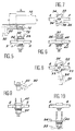
- the assembly of the valve is shown diagrammatically in FIG. 4.
- the internal assembly 20 is placed above the body 1 and held by gravity.
- the actuator 70 is above the internal assembly 20 and held on the latter by gravity.
- the retaining assembly 40 is located under the body 1 and held in place using the collar 32 and the retaining ring 57; however, this device is insufficient and that is why, in normal service, the rods 42 are used both to hold the support plate 41 using locking nuts 61 and to securely maintain the engagement of the internal assembly 20 and body 1, the thinning 59 being engaged in the appendages 35 and the locking shoulders 44 then pressing on the upper face of the cover 26.
- the rods 42 therefore serve above all as tie rods and maintain both the first assembly 20 and the second set 40 securely in place on the body 1.
- valve described here is the subject of specific and simplified dismantling and reassembly operations which justify the interest shown in the invention. This is what will now be described with the aid of FIGS. 5 to 10.
- the first operation consists in removing the actuator 70. This is what is shown in FIG. 5. It suffices in fact to raise the actuator 70 using a manipulator arm terminated by a clamp 90 acting on a suitable handle 95. The pre-centering arches 72 and the chamfer plates 28 on the one hand, the actuator key 73 and the key 30 on the other hand are separated. The actuator 70 can then be examined or replaced.
- the next step is to extract the internal assembly 20. For this, we proceed in two steps.
- the first is an unlock.
- the contact surfaces of the internal assembly 20 and of the body 1 are jammed and the manipulators do not have sufficient force to proceed to direct extraction. It is partly for this reason that a holding assembly 40 has been provided. Indeed, the unscrewing of the nut 47 which is then carried out leads to lifting the support plate 41 and therefore the rods 42.
- the cover 26 hitherto pressed down by the screws 42 and in contact with the locking shoulders 44 is now supported on the unlocking shoulders 45 and raised.
- the retaining ring 57 is pressed by the corner 56 in the end-piece groove 5 and therefore makes the nut 47 integral with the body 1. This step is represented by FIG. 6.
- a clamp 90 is supported on a handle 92 of the cover 26 and prints a rotation in order to arrive at the state of FIG. 8 from the state of FIG. 7.
- the thinnings 59 of the rods 42 which were previously housed in the appendages 35 of the appendage orifices 33, are now found in the orifices proper 34 whose diameter is greater than that of the chamfered ends 43. This rotation was made possible because the unlocking operation described above released the cover 26 from the positioning pins 6.
- the clamp 90 lifts and then removes the internal assembly 20, as shown in FIG. 9. It can then bring it to a work station provided with remote handling tools with more extensive possibilities, which can in particular disjoin the cover 26 of the cage 22.
- the description can be made simply using FIG. 1.
- One begins by unscrewing the immobilizing screw 31 and the stop screw 27 which immobilizes in rotation the cover 26 and the cage 22; these last two parts are then gripped and spaced apart from each other as much as possible and then rotated in such a way that the rod 29 comes out of its groove and can be extracted after the base 32 has been taken out.
- the placement of the second set 40 opposite the first set 20 _ and incidentally the third set 70 _ relative to the body 1 is very advantageous, since it is not necessary to dismantle the second set 40 to extract the first set 20 and more remote manipulations are performed on elements of the second set 40 easy to access because isolated from the rest of the valve.
Landscapes
- Engineering & Computer Science (AREA)
- General Engineering & Computer Science (AREA)
- Mechanical Engineering (AREA)
- Valve Housings (AREA)
- Taps Or Cocks (AREA)
- Quick-Acting Or Multi-Walled Pipe Joints (AREA)
Claims (12)
Applications Claiming Priority (2)
| Application Number | Priority Date | Filing Date | Title |
|---|---|---|---|
| FR8701542A FR2610691B1 (fr) | 1987-02-09 | 1987-02-09 | Vanne telemanipulable |
| FR8701542 | 1987-02-09 |
Publications (2)
| Publication Number | Publication Date |
|---|---|
| EP0301071A1 EP0301071A1 (de) | 1989-02-01 |
| EP0301071B1 true EP0301071B1 (de) | 1991-04-24 |
Family
ID=9347703
Family Applications (1)
| Application Number | Title | Priority Date | Filing Date |
|---|---|---|---|
| EP88901851A Expired - Lifetime EP0301071B1 (de) | 1987-02-09 | 1988-02-09 | Fernmanipulierbares ventil |
Country Status (6)
| Country | Link |
|---|---|
| US (1) | US4917141A (de) |
| EP (1) | EP0301071B1 (de) |
| JP (1) | JPH01502686A (de) |
| KR (1) | KR890700773A (de) |
| FR (1) | FR2610691B1 (de) |
| WO (1) | WO1988005879A1 (de) |
Families Citing this family (11)
| Publication number | Priority date | Publication date | Assignee | Title |
|---|---|---|---|---|
| NO166420C (no) * | 1988-10-14 | 1991-07-31 | Norske Stats Oljeselskap | Ventil. |
| NO166200C (no) * | 1989-02-10 | 1991-06-12 | Norske Stats Oljeselskap | Anordning ved dreieventil. |
| FR2672657B1 (fr) * | 1991-02-13 | 1993-10-29 | Matieres Nucleaires Cie Gle | Appareil pour circuit de fluide, a embase standard et bloc actif remplacable, et procede de remplacement du bloc actif d'un tel appareil. |
| US5529087A (en) * | 1995-02-27 | 1996-06-25 | Lockheed Idaho Technologies Company | System for remotely servicing a top loading captive ball valve |
| DE19854785C1 (de) * | 1998-11-27 | 2000-04-13 | Waeschle Gmbh | Zellenradschleuse mit Ausziehvorrichtung |
| US7434593B2 (en) * | 2002-10-23 | 2008-10-14 | Zurn Industries, Llc | Double check valve assembly |
| US7784483B2 (en) * | 2005-01-21 | 2010-08-31 | Zurn Industries, Llc | Backflow preventer |
| RU2443930C1 (ru) * | 2010-08-20 | 2012-02-27 | Рубен Арутюнович Баласанян | Прибор для профилактических работ на пробковых газовых кранах вводных и внутренних газопроводов |
| WO2020223139A1 (en) * | 2019-05-02 | 2020-11-05 | Swagelok Company | Nut locking coupling for actuated valve |
| RU207831U1 (ru) * | 2021-02-19 | 2021-11-18 | Общество с ограниченной ответственностью "Камимтех" | Клиновая задвижка с цилиндрическим корпусом |
| US12618479B2 (en) * | 2024-09-24 | 2026-05-05 | Itt Manufacturing Enterprises Llc | Valve assembly useful for cryogenic applications |
Citations (1)
| Publication number | Priority date | Publication date | Assignee | Title |
|---|---|---|---|---|
| EP0147924A1 (de) * | 1983-10-31 | 1985-07-10 | Robert Joseph Miskinis | Vorrichtung zum Festsetzen von miteinander verbundenen Elementen für Laboreinrichtungen |
Family Cites Families (14)
| Publication number | Priority date | Publication date | Assignee | Title |
|---|---|---|---|---|
| DE502608C (de) * | 1926-06-22 | 1930-07-16 | Ton Und Steinzeugwerke Akt Ges | Hahn |
| US3111299A (en) * | 1960-09-13 | 1963-11-19 | Donald W Miller | Rotary plug valve |
| US3133722A (en) * | 1961-07-31 | 1964-05-19 | Halliburton Co | Plug valve with removable insert and liner means |
| GB965107A (en) * | 1961-12-01 | 1964-07-29 | William John Courtney Trythall | Fluid flow control valves and means and method for inserting such valves in pipelines |
| IN155180B (de) * | 1980-01-08 | 1985-01-12 | Xomox Corp | |
| DE3071439D1 (en) * | 1980-01-08 | 1986-03-27 | Xomox Corp | Plug valve |
| US4531537A (en) * | 1980-04-21 | 1985-07-30 | Xomox Corporation | Plug valve for reduced leakage |
| GB8319853D0 (en) * | 1983-07-22 | 1983-08-24 | Forsac Valves | Ball valve for pipeline |
| US4617957A (en) * | 1983-07-25 | 1986-10-21 | Xomox Corporation | Rotary plug valve |
| US4671312A (en) * | 1984-05-14 | 1987-06-09 | Axelson, Inc. | Wireline cutting actuator and valve |
| FR2565664B1 (fr) * | 1984-06-07 | 1988-03-25 | Air Liquide | Enceinte de confinement et d'intervention pour le transport et la vidange de bouteilles contenant des gaz toxiques et/ou corrosifs et presentant une fuite ou un defaut de fonctionnement du robinet. |
| US4587990A (en) * | 1984-10-23 | 1986-05-13 | Gripper, Inc. | Modular ball valve |
| DE3520541A1 (de) * | 1985-06-07 | 1986-12-11 | Deutsche Gesellschaft für Wiederaufarbeitung von Kernbrennstoffen mbH, 3000 Hannover | Fernhantierbare und fernbedienbare armatur, insbesondere fuer den heissen bereich radioaktiver anlagen |
| NO159553C (no) * | 1986-03-12 | 1989-01-11 | Norske Stats Oljeselskap | Kuleventil. |
-
1987
- 1987-02-09 FR FR8701542A patent/FR2610691B1/fr not_active Expired
-
1988
- 1988-02-09 JP JP63501824A patent/JPH01502686A/ja active Pending
- 1988-02-09 WO PCT/FR1988/000071 patent/WO1988005879A1/fr not_active Ceased
- 1988-02-09 US US07/278,948 patent/US4917141A/en not_active Expired - Fee Related
- 1988-02-09 EP EP88901851A patent/EP0301071B1/de not_active Expired - Lifetime
- 1988-09-30 KR KR1019880701222A patent/KR890700773A/ko not_active Withdrawn
Patent Citations (1)
| Publication number | Priority date | Publication date | Assignee | Title |
|---|---|---|---|---|
| EP0147924A1 (de) * | 1983-10-31 | 1985-07-10 | Robert Joseph Miskinis | Vorrichtung zum Festsetzen von miteinander verbundenen Elementen für Laboreinrichtungen |
Also Published As
| Publication number | Publication date |
|---|---|
| US4917141A (en) | 1990-04-17 |
| EP0301071A1 (de) | 1989-02-01 |
| KR890700773A (ko) | 1989-04-27 |
| FR2610691A1 (fr) | 1988-08-12 |
| FR2610691B1 (fr) | 1989-03-10 |
| JPH01502686A (ja) | 1989-09-14 |
| WO1988005879A1 (fr) | 1988-08-11 |
Similar Documents
| Publication | Publication Date | Title |
|---|---|---|
| EP0194169B1 (de) | Zerlegbare Tetraederverbindung | |
| EP0501866B1 (de) | Ausrichtstange und Zentriervorrichtung für Behälterdeckel, wobei derartige Stangen Verwendung finden | |
| EP2361713B1 (de) | Vorrichtung zur Verwaltung von Elektroden für Elektroerosionsmaschinen | |
| WO1988005879A1 (fr) | Vanne telemanipulable | |
| FR2532221A1 (fr) | Appareil de saisie et de manipulation de pieces d'usinage pour systemes de soudage au laser et autres systemes analogues | |
| WO2004000504A1 (fr) | Dispositif de tension pour mise en precontrainte d'une tige et procede de tension associe | |
| FR2902235A1 (fr) | Dispositif de transport, de stockage et de transfert de substrats | |
| FR2714709A1 (fr) | Accouplement à ouverture d'urgence alimenté par une double vanne à boisseau sphérique à débordement nul. | |
| FR2601273A1 (fr) | Dispositif pour la pose d'un joint d'etancheite a l'interieur d'une gorge. | |
| WO2000036388A1 (fr) | Dispositif de detection de l'etancheite de la liaison entre les elements d'un dispositif de jonction etanche de deux enceintes isolees du milieu exterieur | |
| FR3046465A1 (fr) | Accessoire de prehension d'un contenant | |
| EP2367651A1 (de) | Giessrohr, vorrichtung zur handhabung des rohrs und ventilansteuervorrichtung | |
| EP0148677A1 (de) | Magnetisches Roboterhandgelenk | |
| FR2646660A1 (fr) | Appareil pour saisir et transporter un objet ainsi qu'etablir une connexion electrique par manipulation a distance | |
| EP0621098B2 (de) | Vorrichtung und Verfahren zum Giessen mit einer zementfreien Verbindung des Schiebeverschlusses mit dem metallurgischen Gefäss | |
| EP0312460A1 (de) | Vorrichtung zur entkuppelbaren Verbindung zweier dichter Hohlräume | |
| FR2574879A1 (fr) | Articulation a rattrapage de tolerances et procede pour articuler entre eux deux elements de structure d'une machine | |
| FR2566312A1 (fr) | Appareil de changement de machoires de manipulateurs | |
| FR3016950A1 (fr) | Raccord pour circuit de transport de fluide et circuit de transport de fluide comprenant un tel raccord | |
| FR2565664A1 (fr) | Enceinte de confinement et d'intervention pour le transport et la vidange de bouteilles contenant des gaz toxiques et/ou corrosifs et presentant une fuite ou un defaut de fonctionnement du robinet. | |
| FR2700487A1 (fr) | Palette de transport de pièces mécaniques usinées et installation automatisée de contrôle dimensionnel utilisant de telles palettes. | |
| EP0109405B1 (de) | Einrichtung zum greifen von gegenständen für manipulator vom robotertyp | |
| CH667826A5 (fr) | Dispositif de serrage de deux elements. | |
| FR2502600A3 (fr) | Appareil destine a saisir des futs a contenu fortement radioactif ouverts ou fermes par un couvercle | |
| WO2010057638A1 (fr) | Element de coulee reutilisable |
Legal Events
| Date | Code | Title | Description |
|---|---|---|---|
| PUAI | Public reference made under article 153(3) epc to a published international application that has entered the european phase |
Free format text: ORIGINAL CODE: 0009012 |
|
| AK | Designated contracting states |
Kind code of ref document: A1 Designated state(s): BE DE GB IT SE |
|
| 17P | Request for examination filed |
Effective date: 19880920 |
|
| 17Q | First examination report despatched |
Effective date: 19891205 |
|
| GRAA | (expected) grant |
Free format text: ORIGINAL CODE: 0009210 |
|
| AK | Designated contracting states |
Kind code of ref document: B1 Designated state(s): BE DE GB IT SE |
|
| REF | Corresponds to: |
Ref document number: 3862542 Country of ref document: DE Date of ref document: 19910529 |
|
| ITF | It: translation for a ep patent filed | ||
| GBT | Gb: translation of ep patent filed (gb section 77(6)(a)/1977) | ||
| PLBE | No opposition filed within time limit |
Free format text: ORIGINAL CODE: 0009261 |
|
| STAA | Information on the status of an ep patent application or granted ep patent |
Free format text: STATUS: NO OPPOSITION FILED WITHIN TIME LIMIT |
|
| 26N | No opposition filed | ||
| EAL | Se: european patent in force in sweden |
Ref document number: 88901851.1 |
|
| PGFP | Annual fee paid to national office [announced via postgrant information from national office to epo] |
Ref country code: BE Payment date: 19960129 Year of fee payment: 9 |
|
| PGFP | Annual fee paid to national office [announced via postgrant information from national office to epo] |
Ref country code: SE Payment date: 19960131 Year of fee payment: 9 Ref country code: GB Payment date: 19960131 Year of fee payment: 9 |
|
| PGFP | Annual fee paid to national office [announced via postgrant information from national office to epo] |
Ref country code: DE Payment date: 19960227 Year of fee payment: 9 |
|
| PG25 | Lapsed in a contracting state [announced via postgrant information from national office to epo] |
Ref country code: GB Effective date: 19970209 |
|
| PG25 | Lapsed in a contracting state [announced via postgrant information from national office to epo] |
Ref country code: SE Effective date: 19970210 |
|
| PG25 | Lapsed in a contracting state [announced via postgrant information from national office to epo] |
Ref country code: BE Effective date: 19970228 |
|
| BERE | Be: lapsed |
Owner name: COMMISSARIAT A L'ENERGIE ATOMIQUE ETABLISSEMENT D Effective date: 19970228 |
|
| GBPC | Gb: european patent ceased through non-payment of renewal fee |
Effective date: 19970209 |
|
| PG25 | Lapsed in a contracting state [announced via postgrant information from national office to epo] |
Ref country code: DE Effective date: 19971101 |
|
| EUG | Se: european patent has lapsed |
Ref document number: 88901851.1 |
|
| PG25 | Lapsed in a contracting state [announced via postgrant information from national office to epo] |
Ref country code: IT Free format text: LAPSE BECAUSE OF NON-PAYMENT OF DUE FEES;WARNING: LAPSES OF ITALIAN PATENTS WITH EFFECTIVE DATE BEFORE 2007 MAY HAVE OCCURRED AT ANY TIME BEFORE 2007. THE CORRECT EFFECTIVE DATE MAY BE DIFFERENT FROM THE ONE RECORDED. Effective date: 20050209 |