EP0621098B2 - Vorrichtung und Verfahren zum Giessen mit einer zementfreien Verbindung des Schiebeverschlusses mit dem metallurgischen Gefäss - Google Patents
Vorrichtung und Verfahren zum Giessen mit einer zementfreien Verbindung des Schiebeverschlusses mit dem metallurgischen Gefäss Download PDFInfo
- Publication number
- EP0621098B2 EP0621098B2 EP93401008A EP93401008A EP0621098B2 EP 0621098 B2 EP0621098 B2 EP 0621098B2 EP 93401008 A EP93401008 A EP 93401008A EP 93401008 A EP93401008 A EP 93401008A EP 0621098 B2 EP0621098 B2 EP 0621098B2
- Authority
- EP
- European Patent Office
- Prior art keywords
- plate
- fixed plate
- discharge opening
- joint surface
- fixed
- Prior art date
- Legal status (The legal status is an assumption and is not a legal conclusion. Google has not performed a legal analysis and makes no representation as to the accuracy of the status listed.)
- Expired - Lifetime
Links
- 238000005266 casting Methods 0.000 title claims abstract description 32
- 238000000034 method Methods 0.000 title claims description 10
- 239000004570 mortar (masonry) Substances 0.000 claims abstract 2
- 239000002184 metal Substances 0.000 claims description 15
- 229910000831 Steel Inorganic materials 0.000 claims description 13
- 239000010959 steel Substances 0.000 claims description 13
- 238000003754 machining Methods 0.000 claims description 7
- 239000000463 material Substances 0.000 claims description 5
- 230000003100 immobilizing effect Effects 0.000 claims description 2
- 230000008569 process Effects 0.000 claims description 2
- 238000007789 sealing Methods 0.000 claims description 2
- 230000006835 compression Effects 0.000 claims 10
- 238000007906 compression Methods 0.000 claims 10
- 239000000835 fiber Substances 0.000 claims 1
- 239000003292 glue Substances 0.000 claims 1
- 238000005304 joining Methods 0.000 abstract description 28
- 238000003825 pressing Methods 0.000 abstract description 4
- 238000006073 displacement reaction Methods 0.000 abstract description 3
- 239000000853 adhesive Substances 0.000 abstract 1
- 230000001070 adhesive effect Effects 0.000 abstract 1
- 239000011819 refractory material Substances 0.000 description 12
- 238000012549 training Methods 0.000 description 9
- 230000009471 action Effects 0.000 description 6
- 230000008859 change Effects 0.000 description 6
- 238000000605 extraction Methods 0.000 description 6
- 239000004568 cement Substances 0.000 description 5
- 238000004140 cleaning Methods 0.000 description 3
- 239000002699 waste material Substances 0.000 description 3
- 230000008901 benefit Effects 0.000 description 2
- 238000001816 cooling Methods 0.000 description 2
- 238000009434 installation Methods 0.000 description 2
- 238000004519 manufacturing process Methods 0.000 description 2
- 230000002829 reductive effect Effects 0.000 description 2
- 239000007787 solid Substances 0.000 description 2
- 230000000712 assembly Effects 0.000 description 1
- 238000000429 assembly Methods 0.000 description 1
- 239000011449 brick Substances 0.000 description 1
- 238000012937 correction Methods 0.000 description 1
- 238000005520 cutting process Methods 0.000 description 1
- 230000001627 detrimental effect Effects 0.000 description 1
- 238000011161 development Methods 0.000 description 1
- 230000000694 effects Effects 0.000 description 1
- 230000003628 erosive effect Effects 0.000 description 1
- 239000007788 liquid Substances 0.000 description 1
- 238000005272 metallurgy Methods 0.000 description 1
- 239000011241 protective layer Substances 0.000 description 1
- 238000011084 recovery Methods 0.000 description 1
- 230000000284 resting effect Effects 0.000 description 1
- 230000000717 retained effect Effects 0.000 description 1
- 230000002441 reversible effect Effects 0.000 description 1
- 238000010008 shearing Methods 0.000 description 1
- 238000012546 transfer Methods 0.000 description 1
Images


Classifications
-
- B—PERFORMING OPERATIONS; TRANSPORTING
- B22—CASTING; POWDER METALLURGY
- B22D—CASTING OF METALS; CASTING OF OTHER SUBSTANCES BY THE SAME PROCESSES OR DEVICES
- B22D41/00—Casting melt-holding vessels, e.g. ladles, tundishes, cups or the like
- B22D41/14—Closures
- B22D41/22—Closures sliding-gate type, i.e. having a fixed plate and a movable plate in sliding contact with each other for selective registry of their openings
- B22D41/24—Closures sliding-gate type, i.e. having a fixed plate and a movable plate in sliding contact with each other for selective registry of their openings characterised by a rectilinearly movable plate
-
- B—PERFORMING OPERATIONS; TRANSPORTING
- B22—CASTING; POWDER METALLURGY
- B22D—CASTING OF METALS; CASTING OF OTHER SUBSTANCES BY THE SAME PROCESSES OR DEVICES
- B22D41/00—Casting melt-holding vessels, e.g. ladles, tundishes, cups or the like
- B22D41/14—Closures
- B22D41/22—Closures sliding-gate type, i.e. having a fixed plate and a movable plate in sliding contact with each other for selective registry of their openings
- B22D41/28—Plates therefor
- B22D41/30—Manufacturing or repairing thereof
-
- B—PERFORMING OPERATIONS; TRANSPORTING
- B22—CASTING; POWDER METALLURGY
- B22D—CASTING OF METALS; CASTING OF OTHER SUBSTANCES BY THE SAME PROCESSES OR DEVICES
- B22D41/00—Casting melt-holding vessels, e.g. ladles, tundishes, cups or the like
- B22D41/14—Closures
- B22D41/22—Closures sliding-gate type, i.e. having a fixed plate and a movable plate in sliding contact with each other for selective registry of their openings
- B22D41/28—Plates therefor
- B22D41/34—Supporting, fixing or centering means therefor
-
- B—PERFORMING OPERATIONS; TRANSPORTING
- B22—CASTING; POWDER METALLURGY
- B22D—CASTING OF METALS; CASTING OF OTHER SUBSTANCES BY THE SAME PROCESSES OR DEVICES
- B22D41/00—Casting melt-holding vessels, e.g. ladles, tundishes, cups or the like
- B22D41/14—Closures
- B22D41/22—Closures sliding-gate type, i.e. having a fixed plate and a movable plate in sliding contact with each other for selective registry of their openings
- B22D41/40—Means for pressing the plates together
Definitions
- the invention relates to a casting device comprising a metallurgical container provided with an orifice casting, especially a converter for the elaboration steel; a slide shutter for said orifice casting, said shutter comprising: at least one fixed refractory plate having an orifice placed opposite the pouring orifice; at least one refractory plate mobile having at least one orifice; of the moving means for moving the movable plate relative to the fixed plate so as to control the covering the holes of the fixed plate and the plate mobile; pressure means which make it possible to tighten the movable plate against the fixed plate.
- FR-A-2 436 923 is a shutter with a shutter plate solid or having a through hole for the metal.
- This shutter plate is disposed between two plates, respectively an upper plate and a lower support plate on which is fixed a pouring tube.
- the top plate is a work plate.
- the shutter plate rubs against its underside with each movement of the drawer. This face is thus eroded relatively quickly which requires changing the upper plate at each change of the sealing plate.
- JP-49-105730 a device for assembling a set of refractory plates without a casting vessel. This device does not have planar function surfaces.
- a device for the replacement of refractories used to transfer liquid steel from a dispatcher to a casting mold has a junction plate, mounted at the end of the tundish orifice, and at least two sets each consisting of a fixed plate and a movable plate secured to a tube of casting. These assemblies are mounted on guide rails, so that a used refractory set can be replaced by a new set, one chasing the other.
- Such a device is provided for replacement refractories during casting, and not between two flows. It can not therefore allow access to the plate junction in order to check it and possibly to change.
- a set of new refractories is introduced on one side of the pouring orifice, while the used refractory assembly is evacuated from the opposite.
- the introduction of refractories must be done alternately on one side then the other of the pouring orifice.
- the device thus requires three distinct zones, namely an introductory zone new refractories, a casting zone, and a zone evacuation of used refractories. Its size is therefore at least equal to three lengths of plates.
- the device does not describe any means to put the refractories in place and remove them easily.
- the present invention relates to a device casting and a method of implementing this device who solve these problems.
- the present invention also relates to the use of a plate according to claim 16.
- the device comprises a surface substantially extending the surface of the connection of the pouring orifice in the introduction / extraction zone, in order to ensure pre-guidance of the fixed plate relative to the junction surface of the pouring orifice to facilitate placement and / or removing at least the fixed plate by sliding on the joining surface.
- junction surface of the orifice casting and the joining surface of the fixed plate are planar.
- the flatness of these two surfaces also makes it easier to in place and / or removal of the fixed plate by sliding on the joining surface of the pouring orifice.
- the surface of junction of the pouring orifice consists of a plate refractory. This plate is changed between two when the container is empty and the steel is not do not run. It is therefore impossible for steel to penetrate between this junction plate and the fixed plate.
- the guide surface should be exactly the same level as the joining surface. But this is not mechanically feasible because machining tolerances.
- the level of the surface of guidance is therefore equal by default (ie to the tolerances machining near) at the joining surface of the pouring orifice, a chamfer being provided for facilitate the placement of the fixed plate on the surface junction of the pouring orifice.
- the pressure means for tighten the joining surface of the fixed plate against the junction surface of the pouring orifice are arranged to act during set-up and / or removal by sliding at least the fixed plate to eliminate the waste possibly remaining on this surface.
- Means of travel to implement place and / or remove the fixed plate by sliding on the junction surface of the pouring orifice are preferably the same as the means to move the plate mobile relative to the fixed plate.
- the device preferably comprises: a frame; a frame for driving the fixed plate; a frame driving the movable plate; moving means the drive frame of the movable plate, these means constituting the means of displacement of the movable plate mentioned above; of the means of securing the training framework of the fixed plate either with the frame or with the training frame of the movable plate.
- the means for securing the drive frame of the fixed plate with the frame or with the drive frame of the movable plate are, in a preferred embodiment, constituted by a two-position latch mounted on the drive frame. of the fixed plate, this lock immobilizing the drive frame of the fixed plate relative to the frame in a first position and relative to the drive frame of the mobile platform in the second position, the moving means of the drive frame the movable plate having a sufficient stroke to move all of the two frames to release the fixed plate of the grip of the pressure means of the fixed plate against the junction surface of the casting orifice.
- the device comprises a fixed stop relative to the frame against which the fixed plate comes into abutment at the end of introduction, the lock comprising means for recovering clearance to lock said fixed plate against the stop via the frame of drive of the fixed plate so that the fixed plate and the drive frame of the fixed plate are together immobilized relative to the frame.
- the clamping means of the fixed plate against the junction area of the pouring orifice are preferably the same as the pressure means for press the movable plate against the fixed plate.
- the joining surface of the pouring orifice may consist of a refractory plate surrounding the pouring orifice mounted on a metal support allowing to ensure a rigid fixation of said refractory plate on the metallurgical container.
- the metal support may have at least a portion of co-planar surface with the refractory plate in order to enlarge the support surface of the fixed plate on the junction surface of the pouring orifice.
- Plots made of a material compatible with that of the refractory plate from the point of view of machining by the same tool can be rigidly attached on the metal support and machined co-planar with the refractory plate so as to enlarge the support surface of the fixed plate against the joining surface.
- At least the fixed plate is brought and / or withdrawn laterally with respect to the cast and slid under pressure prior the fixed plate does not begin to cover and / or discover the pouring orifice of the container.
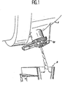
- FIG. 1 shows an overall view of the casting device.
- the metallurgical container is designated by the general reference 1.
- This container can be a dispatcher, or a pocket, or as in the example shown, a converter for the development of steel.
- a slide shutter, designated by the general reference 10 is fixed under the container. The steel contained in the converter is poured into a pocket 3.
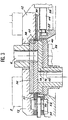
- FIG. 2 shows a schematic view in section of the device.
- the steel wall 2 of the container is covered by a protective layer 4 of refractory material, for example bricks.
- a taphole 6 allows the exit of the metal out of the converter.
- the hole of this hole is delimited by a surface outer 8, flat in the example shown. This surface 8 constitutes a joining surface.
- the slide shutter 10 fixed under the container consists of a frame 12 fixed on the outer wall 2 of the metallurgical container.
- a set two plates namely a fixed plate 14 and a movable plate 16.
- Each of the plates comprises one or more holes for the passage of the metal and is surrounded by a frame, respectively 20 and 22. These two plates are enclosed in a housing 24.
- pressure means schematically represented by the springs 26 allow to press the fixed plate 14 against the movable plate 16.
- An actuating means such as a hydraulic cylinder 28, whose rod is connected to the frame 22 of the movable plate can move the movable plate relative to the fixed plate. This displacement allows, in known manner, to vary the recovery holes of the two plates so to control or stop completely the passage of the metal.
- the drawer includes only two plates, it could include more, for example three or more.
- the housing 24 is in turn pressed by pressing means 30 against the surface 8, which ends the pouring orifice so that the back of the plate fixed, which has a fitting surface 32 adapted at surface 8 be applied sufficiently strongly to create a metal seal.
- Surface qualities in the presence of course are of sufficient quality to ensure this tightness.
- the joining surface must be large enough so that means pressure do not exert effort cantilever. Since the pressure means to tighten against each other the fixed plate and the movable plate are different pressure means for pressing the surface of joining the fixed plate against the surface of junction of the pouring orifice, it is possible to vary pressures per unit area independently one from the other.
- the guiding surface 34 may be slightly behind this plan, as shown in fig 2.
- a chamfer will be then provided on the fixed plate or on the joining surface to facilitate the installation of the fixed plate in absorbing the difference in level.
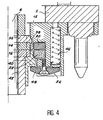
- FIGS. 3 and 4 show another mode embodiment of a casting device according to the invention.
- This device comprises a solid frame 12 fixed on an outer wall 2 of the metallurgical container.
- a plate of junction 36 reported and cemented on the end of the hole casting.
- the outer surface of this plate 36 constitutes the junction surface 8.
- the fixed plate is here consisting of the refractory plate itself and a envelope 38.
- the movable plate consists of the plate refractory itself, a support 40 and a nozzle collector 42, separate or made in one piece with the refractory plate.
- the means of pressure 26 will be described in more detail with reference to FIG. Note, however, that in this embodiment the clamping means of the fixed plate against the surface junction of the pouring orifice are the same as the pressure means for pressing the fixed plate 14 against the movable plate 16. The same means fill therefore two distinct functions.
- the fixed plate is placed in the training frame of the fixed plate 20 and the movable plate in the drive frame of the movable plate 22.
- the rod 44 of the cylinder 28 is retained in a frame housing driving the movable plate 22.
- the cylinder 28 allows to move the movable plate on the fixed plate of in a manner known to control the flow metal out of the metallurgical container.
- FIG. 4 shows a sectional view of the embodiment shown in FIG. perpendicular cutting plane.
- This figure shows in particular the details of the designated means of pressure as a whole by the general reference 26. They comprise a helical spring 46 having one end is resting on the frame 12 and the other on a rocker arm 48. The rocker transmits the action of the spring, in the sense reverse, on the moving plate. Action on the mobile plate is retransmitted to the fixed plate, then to the junction plate 36.
- a latch 50 with two positions.
- This lock is rotatably mounted on the training frame 20 of the fixed plate. In a first position, shown in fig 3, he enters a dwelling 51 of the frame 12. In its other position it penetrates in a housing 53 provided in the training frame of the movable plate 22. In the first position it immobilizes the drive frame of the fixed plate relative to the frame and, in its second position, relative to to the drive frame of the movable plate.
- the cylinder 28 has a stroke sufficient to move all of the two frames enough to release the fixed plate of the right of way of the pressure the fixed plate against the junction surface of the orifice casting.
- the same medium namely the cylinder 28, performs successively two distinct functions.
- it allows to move the moving plate (first position of the latch 50).
- it serves to extracting the part to be changed and setting up a new fixed plate.
- the lock is placed in his second position. The action of the jack allows then move the fixed plate and the plate in a single block mobile, secured together by the lock 50.
- a fixed stop 52 is provided on the frame 12.
- the fixed plate 14 bears against this stop 52 at the end of its introduction.
- the latch 50 has a surface 54 constituting means of catching up play to lock the fixed plate against the stop 52 via the drive frame of the fixed plate.
- This surface 54 is for example a surface constituting a helical cam. So the fixed plate and the frame drive the fixed plate are together immobilized without play compared to the frame. This provision is intended to prevent relative movement of the plate fixed relative to the joining surface. Indeed the movable plate transmits sharp forces to the plate fixed. Such efforts, which are important, tend to move the fixed plate. If it was not blocked, she would move relative to the surface of junction of the pouring orifice, which would have the consequence detrimental wear of the surfaces in contact of the fixed plate and the joining surface.
- FIG. 5 shows a variant of realization of the drawer of Fig 3 in the open position.
- the parts of the same kind are designated by numbers identical reference numbers.
- the lock 50 is placed in said second position in which it secures the training frame 20 of the fixed plate 14 with the drive frame 22 of the movable plate 16.
- the jack 28, whose rod 44 is connected to the frame 22 of the mobile plate, was used to push the set constituted by the two training frames (fixed and mobile) and the plates housed in the openings of these frames (fixed plate 14 and plate mobile 16). This movement has been pursued sufficiently so that the fixed and mobile plates are entirely freed from the action of pressure this way they can be removed freely without have to open a door like this is usually done in the devices of the prior art.
- the installation of new plates is carried out in the same way.
- the fixed plate 14 is first placed inside the opening of the training frame 20 of the fixed plate on a bearing surface of frame 12 located (with close machining tolerances), in the extension of the joining surface.
- the moving plate is then placed on the fixed plate, inside the opening of the drive frame 22 of the movable plate. It is not necessary to connect or disconnect because the cylinder rod remains fixed, during these operations, on the drive frame of the plate mobile.
- the cylinder is then actuated to pull the assembly which penetrates laterally with respect to the pouring orifice under the locking means 50, which immobilizes the two plates without further operation.
- the fixed plate 14 is brought and / or withdrawn and slid under pressure means 30 prior to this that the fixed plate 14 does not begin to cover the orifice casting of the container.
- FIGS. 6 and 7 show two variants embodiment of the junction plate.
- the junction plate of the pouring orifice is constituted a refractory plate 56 surrounding the pouring orifice.
- the plate 56 is secured to a metal support 58 to ensure a rigid fixation on the container metallurgy, for example by means of screws, bolts, studs or the like arranged in the holes 60.
- the surface of the metal support 58 is co-planar, at less in part, with the joining surface 8. This may be obtained by a correction of these two surfaces after assembly of the refractory plate on the support metallic.
- the surface of the metal support 58 allows to enlarge the support surface of the fixed plate on the surface junction and avoid a cantilevered plate fixed.
- Plots 62 are fixed rigidly on the support 58 metal and co-planar machined with refractory plate 56 so as to enlarge the bearing surface of the fixed plate 14 against the joining surface 8.
- the pads 62 are made of a material compatible with that of the refractory plate 56 from the point of view of machining.
- the pads 62 are made in the same refractory material than that of the plate 56. Thus it is possible to machine them simultaneously without difficulty.
Landscapes
- Engineering & Computer Science (AREA)
- Mechanical Engineering (AREA)
- Manufacturing & Machinery (AREA)
- Casting Support Devices, Ladles, And Melt Control Thereby (AREA)
- Carbon Steel Or Casting Steel Manufacturing (AREA)
- Sliding Valves (AREA)
- Furnace Charging Or Discharging (AREA)
- Lift Valve (AREA)
Claims (18)
- Gießvorrichtung, umfassend:wobei die besagte Vorrichtung eine Zufuhr-/Entnahmezone aufweist, um die feste Platte (14) und die bewegliche Platte (16) in den Schieber zuzuführen und um sie daraus zu entnehmen, wobei die feste Platte (14) in der Zufuhr-/Entnahmezone von den Andruckeinrichtungen (30) entlastet ist.einen mit einer Gießöffnung (6) versehenen metallurgischen Behälter, insbesondere einen Konverter für die Stahlerzeugung;einen Schieberverschluss für die besagte Gießöffnung, wobei dieser Verschluss umfasst: mindestens eine feste Feuerfestplatte (14) mit einer gegenüber von der Gießöffnung vorgesehenen Öffnung; mindestens eine bewegliche Feuerfestplatte (16) mit mindestens einer Öffnung; Verschiebeeinrichtungen (28) zum Verschieben der beweglichen Platte (16) im Bezug zur festen Platte (14), um die Überdeckung der Öffnung der festen Platte (14) und der beweglichen Platte (16) zu steuern; Andruckeinrichtungen (26), die es gestatten, die bewegliche Platte (16) gegen die feste Platte (14) anzupressen,wobei die Gießöffnung (6) des metallurgischen Behälters so angeordnet ist, dass sie eine Verbindungsoberfläche (8) mit der festen Platte (14) des Verschlusses aufweist,wobei die feste Platte (14) eine an die Verbindungsoberfläche (8) der Gießöffnung des metallurgischen Behälters angepasste Verbindungsoberfläche (32) aufweist,wobei die Verbindungsoberfläche (8) der Gießöffnung und die Verbindungsoberfläche (32) der festen Platte (14) eben sind,Andruckeinrichtungen (30), die es gestatten, die Verbindungsoberfläche (32) der festen Platte (14) gegen die Verbindungsoberfläche (8) der Gießöffnung zu drücken, so dass zwischen diesen beiden Oberflächen in Abwesenheit von Mörtel, einer zementierten Verbindung oder Fasern, Kleber oder jedem anderen, zur Gewährleistung der Dichtigkeit hinzugefügten Mittel eine Dichtigkeit gewährleistet ist,
- Vorrichtung nach Anspruch 1, dadurch gekennzeichnet, dass sie eine Führungsoberfläche (34) aufweist, welche in der Zufuhr-/Entnahmezone die Verbindungsoberfläche (8) der Gießöffnung merklich verlängert, so dass eine Vorab-Führung der festen Platte (14) in Bezug zur Verbindungsoberfläche der Gießöffnung gewährleistet ist, um das Instellungbringen und/oder das Herausziehen mindestens der festen Platte (14) durch Verschiebung auf der Verbindungsoberfläche zu erleichtern.
- Vorrichtung nach einem der Ansprüche 1 und 2, dadurch gekennzeichnet, dass die Verbindungsoberfläche (8) der Gießöffnung von einer Feuerfestplatte (36,56,58) gebildet wird.
- Vorrichtung nach Anspruch 3, dadurch gekennzeichnet, dass das Niveau der Führungsoberfläche (34) unter dem Niveau der Verbindungsoberfläche (8) der Gießöffnung liegt, wobei eine Fase oder Schräge vorgesehen ist, um das Instellungbringen der festen Platte (14) auf der Verbindungsoberfläche (8) der Gießöffnung zu erleichtern.
- Vorrichtung nach einem der vorangehenden Ansprüche, dadurch gekennzeichnet, dass die Andruckeinrichtungen (30) zum Anpressen der Verbindungsoberfläche (32) der festen Platte (14) gegen die Verbindungsoberfläche (8) der Gießöffnung angeordnet sind, so dass sie während des Instellungbringens und/oder des Herausziehens durch Verschiebung von mindestens der festen Platte (14) wirksam sind, um die eventuell auf dieser Oberfläche zurückgebliebenen Bruchstücke zu beseitigen.
- Vorrichtung nach einem der vorangehenden Ansprüche, dadurch gekennzeichnet, dass die Verschiebeeinrichtungen (28) zum Instellungbringen und/oder Herausziehen der festen Platte (14) durch Verschiebung auf der Verbindungsoberfläche (8) der Gießöffnung dieselben sind, wie die Einrichtungen zum Verschieben der beweglichen Platte (16) in Bezug zur festen Platte (14).
- Vorrichtung nach einem der vorangehenden Ansprüche, dadurch gekennzeichnet, dass sie aufweist: ein Tragelement; einen Mitnehmerrahmen (20) der festen Platte (14); einen Mitnehmerrahmen (22) der beweglichen Platte (16); Einrichtungen zum Verschieben des Mitnehmerrahmens der beweglichen Platte (16), wobei diese Einrichtungen die im Patentanspruch 1 erwähnten Einrichtungen zum Verschieben der beweglichen Platte (16) bilden; Einrichtungen, um den Mitnehmerrahmen der festen Platte (14) entweder mit dem Tragelement oder mit dem Mitnehmerrahmen der beweglichen Platte (16) starr zu verbinden.
- Vorrichtung nach Anspruch 7, dadurch gekennzeichnet, dass die Einrichtungen, um den Mitnehmerrahmen der festen Platte (14) entweder mit dem Tragelement oder mit dem Mitnehmerrahmen der beweglichen Platte (16) starr zu verbinden, von einem auf dem Mitnehmerrahmen der festen Platte (14) angebrachten Riegel (50) mit zwei Stellungen gebildet werden, wobei dieser Riegel in einer ersten Stellung den Mitnehmerrahmen der festen Platte (14) in Bezug zum Tragelement und in der zweiten Stellung in Bezug zum Mitnehmerrahmen der beweglichen Platte (16) unbeweglich macht, wobei die Einrichtungen zum Verschieben des Mitnehmerrahmens der beweglichen Platte (16) eine ausreichende Hublänge aufweisen, um die Gesamtheit der beiden Rahmen zu verschieben, bis die feste Platte (14) aus dem Einflussbereich der Einrichtungen (30) zum Andrücken der festen Platte (14) gegen die Verbindungsoberfläche (8) der Gießöffnung freikommt.
- Vorrichtung nach Anspruch 8, dadurch gekennzeichnet, dass die Vorrichtung einen in Bezug zum Tragelement ortsfesten Anschlag (52) aufweist, gegen den die feste Platte (14) am Ende des Zuführens anschlägt, wobei der Riegel (50) Spielaufnahmeeinrichtungen aufweist, um die besagte feste Platte (14) mittels des Mitnehmerrahmens (20) der festen Platte (14) gegen den Anschlag (52) anliegend zu blockieren, so dass die feste Platte (14) und der Mitnehmerrahmen der festen Platte (14) gemeinsam in Bezug zum Tragelement unbeweglich gemacht werden.
- Vorrichtung nach einem der vorangehenden Ansprüche, dadurch gekennzeichnet, dass die Andruckeinrichtungen zum Anpressen der festen Platte (14) gegen die Verbindungsoberfläche (8) der Gießöffnung dieselben sind, wie die Andruckeinrichtungen (30) zum Andrücken der beweglichen Platte (16) gegen die feste Platte (14).
- Vorrichtung nach einem der Ansprüche 3 bis 10, dadurch gekennzeichnet, dass die Platte 36, welche die Verbindungsoberfläche (8) der Gießöffnung bildet, von einer die Gießöffnung umgebenden Feuerfestplatte (56) gebildet wird, die auf einem metallischen Träger (58) montiert ist, der es gestattet, eine starre Befestigung der besagten Platte auf dem metallurgischen Behälter sicherzustellen.
- Vorrichtung nach Anspruch 11, dadurch gekennzeichnet, dass der metallische Träger (58) mindestens einen Oberflächenteil aufweist, der mit der Feuerfestplatte (56) komplanar ist, so dass die Stütz- oder Auflagefläche der festen Platte (14) auf der Verbindungsoberfläche (8) der Gießöffnung vergrößert wird.
- Vorrichtung nach Anspruch 11 oder 12, dadurch gekennzeichnet, dass Klötze (62) aus einem Material, das unter dem Gesichtspunkt einer Bearbeitung mittels eines selben Werkzeugs mit demjenigen der Feuerfestplatte (56) kompatibel ist, starr auf dem metallischen Träger (58) befestigt sind und komplanar mit der Feuerfestplatte bearbeitet sind, so dass die Stütz- oder Auflagefläche der festen Platte (14) gegen die Verbindungsoberfläche (8) vergrößert wird.
- VERFAHREN zum Austauschen der festen Platte (14) und der beweglichen Platte (16) in einer Vorrichtung nach einem der vorhergehenden Ansprüche, dadurch gekennzeichnet, dass:man eine feste Platte (14) und eine bewegliche Platte (16), die abgenutzt sind, aus den Andruckeinrichtungen herauszieht, indem man sie in Bezug zur Gießöffnung in seitlicher Richtung in eine Zufuhr-/Entnahmezone schiebt;man die feste Platte (14) und die bewegliche Platte (16) aus dem Schieber entnimmt;man eine neue feste Platte (14) und eine neue bewegliche Platte (16) nacheinander oder gleichzeitig in der Zufuhr-/Entnahmezone platziert;man die feste Platte (14) und die bewegliche Platte (16) in seitlicher Richtung unter die Andruckeinrichtungen (30) schiebt.
- Verfahren nach Anspruch 14, dadurch gekennzeichnet, dass mindestens die feste Platte (14) in Bezug zur Gießöffnung in seitlicher Richtung zugeführt und/oder zurückgezogen wird und unter den Andruckeinrichtungen (30) verschoben wird, bevor die feste Platte (14) beginnt, die Gießöffnung des Behälters freizugeben und/oder zu bedecken.
- Verwendung einer Platte in einer Vorrichtung nach einem der Ansprüche 1 bis 13 oder bei einem Verfahren nach einem der Ansprüche 14 oder 15, dadurch gekennzeichnet, dass sie von einer Feuerfestplatte (56) mit einer ebenen Oberfläche gebildet wird, die auf einem metallischen Träger (58) angebracht wird, was es gestattet, eine starre Befestigung der Platte auf dem metallurgischen Behälter durch die Vorspannung von Schrauben, Schraubenbolzen, Bolzen oder dergleichen sicherzustellen.
- Verwendung nach Anspruch 16, dadurch gekennzeichnet, dass der metallische Träger (58) mindestens einen Oberflächenteil aufweist, der mit der ebenen Oberfläche der Feuerfestplatte (56) komplanar ist.
- Verwendung einer Platte nach Anspruch 16 oder 17, dadurch gekennzeichnet, dass Klötze (62) aus einem Material, das unter dem Gesichtspunkt einer Bearbeitung mittels eines selben Werkzeugs mit demjenigen der Feuerfestplatte (56) kompatibel ist, starr auf dem metallischen Träger (58) befestigt und komplanar mit der Feuerfestplatte bearbeitet sind.
Priority Applications (14)
| Application Number | Priority Date | Filing Date | Title |
|---|---|---|---|
| EP93401008A EP0621098B2 (de) | 1993-04-19 | 1993-04-19 | Vorrichtung und Verfahren zum Giessen mit einer zementfreien Verbindung des Schiebeverschlusses mit dem metallurgischen Gefäss |
| AT93401008T ATE220588T1 (de) | 1993-04-19 | 1993-04-19 | Vorrichtung und verfahren zum giessen mit einer zementfreien verbindung des schiebeverschlusses mit dem metallurgischen gefäss |
| ES93401008T ES2176196T5 (es) | 1993-04-19 | 1993-04-19 | Dispositivo de colada que incluye una union sin cemento de un contenedor metalurgico a un obturador de cajon, y procedimiento de aplicacion de dicho dispositivo. |
| DE69332116T DE69332116T3 (de) | 1993-04-19 | 1993-04-19 | Vorrichtung und Verfahren zum Gießen mit einer zementfreien Verbindung des Schiebeverschlusses mit dem metallurgischen Gefäß |
| US08/214,286 US5400930A (en) | 1993-04-19 | 1994-03-17 | Slide gate valve having a cementless joint between the valve and a metallurgical vessel |
| AU65693/94A AU666624B2 (en) | 1993-04-19 | 1994-04-19 | Slide gate valve having a cementless joint between the valve and a metallurgical vessel |
| MXPA94002807A MXPA94002807A (es) | 1993-04-19 | 1994-04-19 | Valvula corrediza para colada con union sin cemento entre la valvula y un recipiente metalurgico. |
| BR9404968A BR9404968A (pt) | 1993-04-19 | 1994-04-19 | Válvula de gaveta corrediça pra regular um fluxo de metal em fusão proveniente de um vaso metalúrgico e processo de substituição de placa de válvula para uma válvula de gaveta corrediça corrediça instalada em um vaso metalúrgico |
| PCT/EP1994/001211 WO1994023867A1 (en) | 1993-04-19 | 1994-04-19 | Slide gate valve having a cementless joint between the valve and a metallurgical vessel |
| RU94046258A RU2145534C1 (ru) | 1993-04-19 | 1994-04-19 | Скользящий затвор шиберного типа и способ замены плиты затвора |
| CN94190210A CN1057718C (zh) | 1993-04-19 | 1994-04-19 | 在阀与冶炼炉桶之间具有非胶结接合的滑动闸阀 |
| CA002137372A CA2137372C (en) | 1993-04-19 | 1994-04-19 | Slide gate valve having a cementless joint between the valve and a metallurgical vessel |
| JP52277194A JP3259962B2 (ja) | 1993-04-19 | 1994-04-19 | 摺動ゲート弁装置および該装置用固定プレートの交換方法 |
| US08/939,332 USRE36364E (en) | 1993-04-19 | 1997-09-29 | Slide gate valve having a cementless joint between the valve and the metallurgical vessel |
Applications Claiming Priority (1)
| Application Number | Priority Date | Filing Date | Title |
|---|---|---|---|
| EP93401008A EP0621098B2 (de) | 1993-04-19 | 1993-04-19 | Vorrichtung und Verfahren zum Giessen mit einer zementfreien Verbindung des Schiebeverschlusses mit dem metallurgischen Gefäss |
Publications (3)
| Publication Number | Publication Date |
|---|---|
| EP0621098A1 EP0621098A1 (de) | 1994-10-26 |
| EP0621098B1 EP0621098B1 (de) | 2002-07-17 |
| EP0621098B2 true EP0621098B2 (de) | 2005-11-23 |
Family
ID=8214700
Family Applications (1)
| Application Number | Title | Priority Date | Filing Date |
|---|---|---|---|
| EP93401008A Expired - Lifetime EP0621098B2 (de) | 1993-04-19 | 1993-04-19 | Vorrichtung und Verfahren zum Giessen mit einer zementfreien Verbindung des Schiebeverschlusses mit dem metallurgischen Gefäss |
Country Status (13)
| Country | Link |
|---|---|
| US (2) | US5400930A (de) |
| EP (1) | EP0621098B2 (de) |
| JP (1) | JP3259962B2 (de) |
| CN (1) | CN1057718C (de) |
| AT (1) | ATE220588T1 (de) |
| AU (1) | AU666624B2 (de) |
| BR (1) | BR9404968A (de) |
| CA (1) | CA2137372C (de) |
| DE (1) | DE69332116T3 (de) |
| ES (1) | ES2176196T5 (de) |
| MX (1) | MXPA94002807A (de) |
| RU (1) | RU2145534C1 (de) |
| WO (1) | WO1994023867A1 (de) |
Families Citing this family (13)
| Publication number | Priority date | Publication date | Assignee | Title |
|---|---|---|---|---|
| BE1005987A3 (fr) * | 1992-06-16 | 1994-04-12 | Int Ind Eng Sa | Dispositif de regulation d'un debit de coulee. |
| ES2117110T3 (es) * | 1993-04-19 | 1998-08-01 | Vesuvius France Sa | Juego de elementos refractarios para un obturador de colada y procedimiento para cambiar dicho juego. |
| ATE178823T1 (de) * | 1995-02-17 | 1999-04-15 | Stopinc Ag | Schieberverschluss-system für einen metallschmelze enthaltenden behälter |
| ZA975908B (en) * | 1996-07-18 | 1998-03-30 | Stopinc Ag | Sliding gate valve for a vessel containing molten metal. |
| DE10033904A1 (de) * | 2000-07-12 | 2002-01-31 | Stopinc Ag Huenenberg | Schieberverschluss zum Vergiessen von Metallschmelze, sowie eine dazugehörige feuerfeste Platteneinheit |
| WO2005024069A2 (de) * | 2003-08-29 | 2005-03-17 | Stopinc Aktiengesellschaft | Abstichvorrichtung für ein schmelzgefäss, insbesondere für einen konverter |
| CN102006952B (zh) * | 2008-04-17 | 2016-03-23 | 斯托品克股份公司 | 闭锁板以及在用于金属熔体的容器的出口处的滑动闭锁器 |
| JP5481374B2 (ja) * | 2008-05-16 | 2014-04-23 | 黒崎播磨株式会社 | スライディングノズル装置 |
| US20130048897A1 (en) * | 2011-08-31 | 2013-02-28 | P D K Llc | Exchangeable valve plate assembly for a molten metal slide gate valve |
| PL2979777T3 (pl) * | 2013-03-27 | 2019-01-31 | Krosakiharima Corporation | Urządzenie przesuwnej dyszy |
| CN103525973B (zh) * | 2013-09-30 | 2015-07-29 | 马鞍山利尔开元新材料有限公司 | 一种滑板挡渣出钢转炉机构 |
| EP3587002B1 (de) * | 2018-06-26 | 2020-12-16 | Refractory Intellectual Property GmbH & Co. KG | Schiebeverschluss für ein metallurgisches gefäss |
| PL3930941T3 (pl) * | 2019-02-28 | 2024-02-26 | Vesuvius Group, S.A. | Zawór zasuwowy zawierający wózek |
Family Cites Families (19)
| Publication number | Priority date | Publication date | Assignee | Title |
|---|---|---|---|---|
| DE2027881B2 (de) * | 1970-06-06 | 1979-12-13 | Schloemann-Siemag Ag, 4000 Duesseldorf | Vorrichtung zur Erneuerung der Stahlzuführung vom Zwischenbehälter zur Kokille einer Stranggießanlage |
| JPS6015429B2 (ja) * | 1973-02-13 | 1985-04-19 | 黒崎窯業株式会社 | スライディングノズル装置の面圧負荷設定法 |
| BE841397A (fr) * | 1975-05-30 | 1976-09-01 | Dispositif de fermeture a coulisse destine, en particulier, a des convertisseurs | |
| NL187197C (nl) * | 1978-09-25 | 1991-07-01 | Uss Eng & Consult | Inrichting voor het regelen van de stroming van vloeibaar metaal. |
| GB2043217B (en) * | 1979-03-02 | 1982-10-20 | Flogates Ltd | Spring device for sliding gate valve |
| DE2924118C2 (de) * | 1979-06-15 | 1983-03-31 | Zimmermann & Jansen GmbH, 5160 Düren | Schieberverschluß für eine Gießpfanne |
| US4415103A (en) * | 1979-09-07 | 1983-11-15 | Uss Engineers And Consultants, Inc. | Full throttle valve and method of tube and gate change |
| US4545512A (en) * | 1981-01-19 | 1985-10-08 | Uss Engineers & Consultants, Inc. | Full throttle valve and method of tube and gate change |
| US4582232A (en) * | 1984-06-19 | 1986-04-15 | Flo-Con Systems, Inc. | Valve, clamp, refractory and method |
| DE3512798C1 (de) * | 1985-04-10 | 1986-02-06 | Stopinc Ag, Baar | Schiebeverschluss fuer Metallschmelze enthaltende Gefaesse |
| DE8514458U1 (de) * | 1985-05-15 | 1985-07-04 | Brohltal-Deumag AG, 5401 Urmitz | Schieberplatte |
| DE8528085U1 (de) * | 1985-10-02 | 1987-02-05 | Dahlhoff, Friedrich-Wilhelm, 5804 Herdecke | Schieberverschluß für den Ausguß von Metallschmelze enthaltenden Behältern |
| AT386422B (de) * | 1986-11-13 | 1988-08-25 | Voest Alpine Ag | Vorrichtung zum ausbau von in die abstichoeffnung metallurgischer gefaesse eingesetzten lochsteinen |
| DE3731021A1 (de) * | 1987-09-11 | 1989-03-23 | Mannesmann Ag | Ring fuer drehschieberverschluss |
| DE4006064A1 (de) * | 1990-02-26 | 1991-08-29 | Zimmermann & Jansen Gmbh | Verschlussvorrichtung fuer die boden-ausgussoeffnung einer giesspfanne |
| US5004131A (en) * | 1990-04-16 | 1991-04-02 | Bethlehem Steel Corporation | Molten metal slide gate valve |
| DE4023484A1 (de) * | 1990-07-24 | 1992-02-06 | Didier Werke Ag | Einrichtung zum wechseln eines giessrohres an einem metallurgischen gefaess |
| US5118016A (en) * | 1990-09-27 | 1992-06-02 | Martin & Pagenstecher, Inc. | Bottom pour tiles with self sealing joint for pouring liquid steel |
| FR2681804B1 (fr) * | 1991-09-27 | 1993-11-19 | Boulonnais Terres Refractaires | Perfectionnement apportes aux obturateurs du trou de coulee d'un convertisseur. |
-
1993
- 1993-04-19 DE DE69332116T patent/DE69332116T3/de not_active Expired - Fee Related
- 1993-04-19 ES ES93401008T patent/ES2176196T5/es not_active Expired - Lifetime
- 1993-04-19 EP EP93401008A patent/EP0621098B2/de not_active Expired - Lifetime
- 1993-04-19 AT AT93401008T patent/ATE220588T1/de not_active IP Right Cessation
-
1994
- 1994-03-17 US US08/214,286 patent/US5400930A/en not_active Ceased
- 1994-04-19 BR BR9404968A patent/BR9404968A/pt not_active IP Right Cessation
- 1994-04-19 MX MXPA94002807A patent/MXPA94002807A/es not_active IP Right Cessation
- 1994-04-19 WO PCT/EP1994/001211 patent/WO1994023867A1/en not_active Ceased
- 1994-04-19 JP JP52277194A patent/JP3259962B2/ja not_active Expired - Fee Related
- 1994-04-19 AU AU65693/94A patent/AU666624B2/en not_active Ceased
- 1994-04-19 RU RU94046258A patent/RU2145534C1/ru active
- 1994-04-19 CA CA002137372A patent/CA2137372C/en not_active Expired - Fee Related
- 1994-04-19 CN CN94190210A patent/CN1057718C/zh not_active Expired - Fee Related
-
1997
- 1997-09-29 US US08/939,332 patent/USRE36364E/en not_active Expired - Lifetime
Also Published As
| Publication number | Publication date |
|---|---|
| CA2137372C (en) | 2007-06-26 |
| ES2176196T5 (es) | 2006-05-01 |
| ATE220588T1 (de) | 2002-08-15 |
| BR9404968A (pt) | 1999-06-15 |
| CN1057718C (zh) | 2000-10-25 |
| EP0621098B1 (de) | 2002-07-17 |
| JPH07508223A (ja) | 1995-09-14 |
| JP3259962B2 (ja) | 2002-02-25 |
| ES2176196T3 (es) | 2002-12-01 |
| RU2145534C1 (ru) | 2000-02-20 |
| MXPA94002807A (es) | 2005-01-28 |
| CA2137372A1 (en) | 1994-10-27 |
| CN1107274A (zh) | 1995-08-23 |
| WO1994023867A1 (en) | 1994-10-27 |
| AU666624B2 (en) | 1996-02-15 |
| DE69332116T2 (de) | 2003-03-06 |
| EP0621098A1 (de) | 1994-10-26 |
| AU6569394A (en) | 1994-11-08 |
| US5400930A (en) | 1995-03-28 |
| USRE36364E (en) | 1999-11-02 |
| DE69332116D1 (de) | 2002-08-22 |
| DE69332116T3 (de) | 2006-09-28 |
| RU94046258A (ru) | 1996-10-27 |
Similar Documents
| Publication | Publication Date | Title |
|---|---|---|
| EP0621098B2 (de) | Vorrichtung und Verfahren zum Giessen mit einer zementfreien Verbindung des Schiebeverschlusses mit dem metallurgischen Gefäss | |
| EP0192019B1 (de) | Vorrichtung zur Zuführung und Auswechselung einer Giessdüse | |
| EP2386368A1 (de) | Interne Düse für den Transfer von flüssigem Metall in einem Behälter, Einspannsystem für diese Düse und Ausflussvorrichtung | |
| LU85957A1 (fr) | Plaque refractaire et buse de coulee,et procede de montage de plaques refractaires dans une vanne coulissante | |
| FR2701411A1 (fr) | Procédé pour remplir un moule de coulée et récipient pour sa mise en Óoeuvre. | |
| EP0825910B1 (de) | Vorrichtung und verfahren zum welchseln eines tauchrohres am zwischengefäss einer stranggussanlage für stahl | |
| LU83917A1 (fr) | Dispositif d'accouplement d'une tige de percage du trou de coulee d'un four a cuve a l'outil de travail d'une machine de percage | |
| EP0621097B1 (de) | Keramischer Bausatz für einen Giessverschluss und Verfahren zum Wechselen desselben | |
| EP0301071B1 (de) | Fernmanipulierbares ventil | |
| FR2551374A1 (fr) | Dispositif pour plaques refractaires d'obturateurs coulissants | |
| FR2476527A1 (fr) | Dispositif de retenue de pieces pour les operations de honage | |
| EP0348250B1 (de) | Vorrichtung zum Öffnen und Schliessen eines Filters in einer Kernanlage und Verfahren zum Auswechseln in einer Filtergarnitur | |
| LU81399A1 (fr) | Vanne tournante pour la coulee d'un metal liquide | |
| EP2367648B1 (de) | Giesspfannenrohr für flüssigmetallgussanlage | |
| BE1008394A6 (fr) | Dispositif de raccordement et d'echange d'un tube de coulee sur un recipient contenant un metal en fusion. | |
| FR2740368A1 (fr) | Procede de reutilisation de plaques de fermeture a tiroir et plaque pour cette fermeture | |
| FR2627405A1 (fr) | Procede de filage de metal, specialement d'aluminium, et presse de filage pour la mise en oeuvre du procede | |
| WO1989002800A1 (fr) | Tube de coulee pour dispositif de fermeture coulissante | |
| FR2745210A1 (fr) | Unite coulissante pour un conteneur metallurgique, et plaque associee | |
| EP2186632A1 (de) | Mounting system for sliding punches in a tablet press | |
| FR2742684A1 (fr) | Tiroir de changement de plaques pour un conteneur metallurgique et jeu de plaques pour ce tiroir | |
| EP0646053B1 (de) | Vorrichtung zur durchflussregelung eines flüssigen metallstromes | |
| LU83061A1 (fr) | Perfectionnement aux dispositifs de coulee d'acier liquide | |
| EP0721559A1 (de) | Wiederverwendbare rinnenentleerungsvorrichtung fuer metallurgische einrichtungenund deren verwendung | |
| FR2750901A1 (fr) | Procede de deblocage d'une billette dans une presse a filer |
Legal Events
| Date | Code | Title | Description |
|---|---|---|---|
| PUAI | Public reference made under article 153(3) epc to a published international application that has entered the european phase |
Free format text: ORIGINAL CODE: 0009012 |
|
| AK | Designated contracting states |
Kind code of ref document: A1 Designated state(s): AT BE DE ES FR GB IT |
|
| 17P | Request for examination filed |
Effective date: 19941116 |
|
| 17Q | First examination report despatched |
Effective date: 19980706 |
|
| GRAG | Despatch of communication of intention to grant |
Free format text: ORIGINAL CODE: EPIDOS AGRA |
|
| GRAG | Despatch of communication of intention to grant |
Free format text: ORIGINAL CODE: EPIDOS AGRA |
|
| GRAG | Despatch of communication of intention to grant |
Free format text: ORIGINAL CODE: EPIDOS AGRA |
|
| GRAH | Despatch of communication of intention to grant a patent |
Free format text: ORIGINAL CODE: EPIDOS IGRA |
|
| GRAH | Despatch of communication of intention to grant a patent |
Free format text: ORIGINAL CODE: EPIDOS IGRA |
|
| GRAA | (expected) grant |
Free format text: ORIGINAL CODE: 0009210 |
|
| AK | Designated contracting states |
Kind code of ref document: B1 Designated state(s): AT BE DE ES FR GB IT |
|
| REF | Corresponds to: |
Ref document number: 220588 Country of ref document: AT Date of ref document: 20020815 Kind code of ref document: T |
|
| REG | Reference to a national code |
Ref country code: GB Ref legal event code: FG4D Free format text: NOT ENGLISH |
|
| GBT | Gb: translation of ep patent filed (gb section 77(6)(a)/1977) |
Effective date: 20020721 |
|
| REF | Corresponds to: |
Ref document number: 69332116 Country of ref document: DE Date of ref document: 20020822 |
|
| REG | Reference to a national code |
Ref country code: ES Ref legal event code: FG2A Ref document number: 2176196 Country of ref document: ES Kind code of ref document: T3 |
|
| PLBQ | Unpublished change to opponent data |
Free format text: ORIGINAL CODE: EPIDOS OPPO |
|
| PLBI | Opposition filed |
Free format text: ORIGINAL CODE: 0009260 |
|
| PLBF | Reply of patent proprietor to notice(s) of opposition |
Free format text: ORIGINAL CODE: EPIDOS OBSO |
|
| 26 | Opposition filed |
Opponent name: STOPINC AG Effective date: 20030417 |
|
| PLBB | Reply of patent proprietor to notice(s) of opposition received |
Free format text: ORIGINAL CODE: EPIDOSNOBS3 |
|
| PLAQ | Examination of admissibility of opposition: information related to despatch of communication + time limit deleted |
Free format text: ORIGINAL CODE: EPIDOSDOPE2 |
|
| PLAR | Examination of admissibility of opposition: information related to receipt of reply deleted |
Free format text: ORIGINAL CODE: EPIDOSDOPE4 |
|
| PLBQ | Unpublished change to opponent data |
Free format text: ORIGINAL CODE: EPIDOS OPPO |
|
| PLAB | Opposition data, opponent's data or that of the opponent's representative modified |
Free format text: ORIGINAL CODE: 0009299OPPO |
|
| PLBP | Opposition withdrawn |
Free format text: ORIGINAL CODE: 0009264 |
|
| PUAH | Patent maintained in amended form |
Free format text: ORIGINAL CODE: 0009272 |
|
| STAA | Information on the status of an ep patent application or granted ep patent |
Free format text: STATUS: PATENT MAINTAINED AS AMENDED |
|
| 27A | Patent maintained in amended form |
Effective date: 20051123 |
|
| AK | Designated contracting states |
Kind code of ref document: B2 Designated state(s): AT BE DE ES FR GB IT |
|
| GBTA | Gb: translation of amended ep patent filed (gb section 77(6)(b)/1977) | ||
| REG | Reference to a national code |
Ref country code: ES Ref legal event code: DC2A Date of ref document: 20060104 Kind code of ref document: T5 |
|
| PGFP | Annual fee paid to national office [announced via postgrant information from national office to epo] |
Ref country code: ES Payment date: 20090427 Year of fee payment: 17 |
|
| PGFP | Annual fee paid to national office [announced via postgrant information from national office to epo] |
Ref country code: IT Payment date: 20090429 Year of fee payment: 17 Ref country code: FR Payment date: 20090417 Year of fee payment: 17 Ref country code: DE Payment date: 20090429 Year of fee payment: 17 Ref country code: AT Payment date: 20090401 Year of fee payment: 17 |
|
| PGFP | Annual fee paid to national office [announced via postgrant information from national office to epo] |
Ref country code: BE Payment date: 20090528 Year of fee payment: 17 |
|
| PGFP | Annual fee paid to national office [announced via postgrant information from national office to epo] |
Ref country code: GB Payment date: 20090429 Year of fee payment: 17 |
|
| BERE | Be: lapsed |
Owner name: S.A. *VESUVIUS FRANCE Effective date: 20100430 |
|
| GBPC | Gb: european patent ceased through non-payment of renewal fee |
Effective date: 20100419 |
|
| PG25 | Lapsed in a contracting state [announced via postgrant information from national office to epo] |
Ref country code: AT Free format text: LAPSE BECAUSE OF NON-PAYMENT OF DUE FEES Effective date: 20100419 |
|
| PG25 | Lapsed in a contracting state [announced via postgrant information from national office to epo] |
Ref country code: DE Free format text: LAPSE BECAUSE OF NON-PAYMENT OF DUE FEES Effective date: 20101103 |
|
| PG25 | Lapsed in a contracting state [announced via postgrant information from national office to epo] |
Ref country code: IT Free format text: LAPSE BECAUSE OF NON-PAYMENT OF DUE FEES Effective date: 20100419 Ref country code: BE Free format text: LAPSE BECAUSE OF NON-PAYMENT OF DUE FEES Effective date: 20100430 Ref country code: GB Free format text: LAPSE BECAUSE OF NON-PAYMENT OF DUE FEES Effective date: 20100419 |
|
| REG | Reference to a national code |
Ref country code: ES Ref legal event code: FD2A Effective date: 20110715 |
|
| PG25 | Lapsed in a contracting state [announced via postgrant information from national office to epo] |
Ref country code: ES Free format text: LAPSE BECAUSE OF NON-PAYMENT OF DUE FEES Effective date: 20110705 |
|
| REG | Reference to a national code |
Ref country code: FR Ref legal event code: ST Effective date: 20110729 |
|
| PG25 | Lapsed in a contracting state [announced via postgrant information from national office to epo] |
Ref country code: ES Free format text: LAPSE BECAUSE OF NON-PAYMENT OF DUE FEES Effective date: 20100420 |
|
| PG25 | Lapsed in a contracting state [announced via postgrant information from national office to epo] |
Ref country code: FR Free format text: LAPSE BECAUSE OF NON-PAYMENT OF DUE FEES Effective date: 20100430 |