EP0301113A1 - Dispositif pour sectionner des pieux tubulaires de fondation sous l'eau - Google Patents
Dispositif pour sectionner des pieux tubulaires de fondation sous l'eau Download PDFInfo
- Publication number
- EP0301113A1 EP0301113A1 EP87110888A EP87110888A EP0301113A1 EP 0301113 A1 EP0301113 A1 EP 0301113A1 EP 87110888 A EP87110888 A EP 87110888A EP 87110888 A EP87110888 A EP 87110888A EP 0301113 A1 EP0301113 A1 EP 0301113A1
- Authority
- EP
- European Patent Office
- Prior art keywords
- pile
- supporting shaft
- wall
- tool
- water
- Prior art date
- Legal status (The legal status is an assumption and is not a legal conclusion. Google has not performed a legal analysis and makes no representation as to the accuracy of the status listed.)
- Granted
Links
- XLYOFNOQVPJJNP-UHFFFAOYSA-N water Substances O XLYOFNOQVPJJNP-UHFFFAOYSA-N 0.000 title claims abstract description 45
- 238000005520 cutting process Methods 0.000 title claims abstract description 31
- 230000001681 protective effect Effects 0.000 claims description 18
- 238000000034 method Methods 0.000 claims description 15
- 238000003780 insertion Methods 0.000 claims description 9
- 230000037431 insertion Effects 0.000 claims description 9
- 239000013049 sediment Substances 0.000 claims description 8
- 238000010304 firing Methods 0.000 claims description 3
- 238000005422 blasting Methods 0.000 claims description 2
- 230000006835 compression Effects 0.000 claims 1
- 238000007906 compression Methods 0.000 claims 1
- 238000005553 drilling Methods 0.000 description 9
- 239000007789 gas Substances 0.000 description 4
- 238000004519 manufacturing process Methods 0.000 description 3
- 239000000725 suspension Substances 0.000 description 3
- 230000035515 penetration Effects 0.000 description 2
- 229910000831 Steel Inorganic materials 0.000 description 1
- 238000005299 abrasion Methods 0.000 description 1
- 238000013459 approach Methods 0.000 description 1
- 230000005540 biological transmission Effects 0.000 description 1
- 238000001816 cooling Methods 0.000 description 1
- 230000001934 delay Effects 0.000 description 1
- 238000013461 design Methods 0.000 description 1
- 238000011161 development Methods 0.000 description 1
- 230000018109 developmental process Effects 0.000 description 1
- 238000006073 displacement reaction Methods 0.000 description 1
- 230000000694 effects Effects 0.000 description 1
- 230000007613 environmental effect Effects 0.000 description 1
- 238000004880 explosion Methods 0.000 description 1
- 239000002737 fuel gas Substances 0.000 description 1
- 230000002401 inhibitory effect Effects 0.000 description 1
- 238000009434 installation Methods 0.000 description 1
- 239000007788 liquid Substances 0.000 description 1
- 230000036961 partial effect Effects 0.000 description 1
- 239000002245 particle Substances 0.000 description 1
- 230000002093 peripheral effect Effects 0.000 description 1
- 230000036316 preload Effects 0.000 description 1
- 238000012545 processing Methods 0.000 description 1
- 230000001141 propulsive effect Effects 0.000 description 1
- 239000002994 raw material Substances 0.000 description 1
- 230000002829 reductive effect Effects 0.000 description 1
- 230000000284 resting effect Effects 0.000 description 1
- 230000002441 reversible effect Effects 0.000 description 1
- 239000013535 sea water Substances 0.000 description 1
- 238000000926 separation method Methods 0.000 description 1
- 230000035939 shock Effects 0.000 description 1
- 239000007787 solid Substances 0.000 description 1
- 125000006850 spacer group Chemical group 0.000 description 1
- 239000010959 steel Substances 0.000 description 1
Images



Classifications
-
- E—FIXED CONSTRUCTIONS
- E02—HYDRAULIC ENGINEERING; FOUNDATIONS; SOIL SHIFTING
- E02D—FOUNDATIONS; EXCAVATIONS; EMBANKMENTS; UNDERGROUND OR UNDERWATER STRUCTURES
- E02D9/00—Removing sheet piles bulkheads, piles, mould-pipes or other moulds or parts thereof
- E02D9/04—Removing sheet piles bulkheads, piles, mould-pipes or other moulds or parts thereof by cutting-off under water
-
- E—FIXED CONSTRUCTIONS
- E21—EARTH OR ROCK DRILLING; MINING
- E21B—EARTH OR ROCK DRILLING; OBTAINING OIL, GAS, WATER, SOLUBLE OR MELTABLE MATERIALS OR A SLURRY OF MINERALS FROM WELLS
- E21B7/00—Special methods or apparatus for drilling
- E21B7/12—Underwater drilling
- E21B7/124—Underwater drilling with underwater tool drive prime mover, e.g. portable drilling rigs for use on underwater floors
Definitions
- the invention relates to a method and a device for separating tubular foundation piles under water, in which the wall of the pile is severed by a separating tool inserted into the interior thereof.
- the object of the invention is now to provide a method and an apparatus for separating tubular foundation piles under water of the type mentioned at the outset, which also permit reliable separation of foundation piles in a simple manner even at great water depth, even at a point still below the seabed are applicable from a work ship.
- the attachment and clamping of the implement on the upper edge of the foundation pile can also be carried out relatively quickly and easily from a work ship, the cutting or firing tool located at the lower end of the elongated supporting shaft inserted into the interior of the pile also allowing the pile to be attached to be separated from a place lying under the sea floor, so that no obstacle from the sea floor remains.
- the invention further relates to a device for separating tubular foundation piles under water of the type mentioned in the introduction, which is provided with the features of claim 8.
- This device can be lowered on the crane rope of a working ship and placed so centered on the upper edge of the tubular foundation pile to be separated that the elongated, protruding supporting shaft protrudes centrally into the foundation pile.
- the clamping devices then fix the implement against the circumferential wall of the pile, so that at the same time a centering and a reliable mounting against vertical and horizontal movements, as well as against any torques acting on the cutting tool when cutting the pile wall is achieved.
- the device When using an electro-hydraulic work unit with hydraulic motors that is lowered under water with the implement for rotating the supporting shaft or the tool carrier, and in each case driven by electric motors, either in a closed circuit with a pressure medium container carried along ter connected or in the open circuit simply sucking ambient water, the device can work with great efficiency even in very large water depths without long pressure medium lines.
- the advantageously tubular supporting shaft or the tool carrier is equipped with cutting edges at the lower end, the sediments deposited in the foundation pile to be separated can be simultaneously loosened and washed away when the supporting shaft is inserted into the interior of the foundation pile, so that even with one initially almost completely with solids filled pile, the cutting or burning tool can be inserted to the depth provided for the desired separating cut.
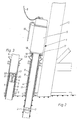
- the implement 1 shown in FIGS. 1 and 2 is lowered on the crane rope 6 of the crane 12 of a work ship 7 next to an oil rig leg 10 under water onto a pile 8, which is attached to a pole bracket attached to the oil rig leg 10 by an annular gap between the pile and the Pile bracket 9 filling concrete layer 11 is permanently connected.
- the working device 1 has an electro-hydraulic drive unit 5, which is supplied with electrical energy via a umbilical 16 hanging from a winch 15 of the working ship 7.
- the umbilical 16 also contains the necessary signal and control lines in a conventional manner.
- the implement 1 also has an elongated, downwardly protruding protective tube 4, through the interior of which a support shaft 3 extends concentrically, which carries a tool holder 2 at its protruding lower end.
- An insertion cone 13 is also arranged around the protective tube 4.
- the length of the implement 1 is dimensioned such that it can be tilted into the position shown in broken lines in FIG. 1 after the conical tool carrier 2 has been inserted into the top opening of the tubular pile 8 by slightly lowering the boom 12 to collide with the pile guide 14 attached to the platform leg. From this position, the implement 1 is then in the in Fig. 2nd shown position lowered, the insertion cone 13 automatically centers the implement 1 on the pile 8 so that the support plate 17 sits on the upper edge of the pile 8.
- clamping jaws 19, which are designed in the embodiment shown as segments of the insertion cone 13, are pressed against the outer peripheral wall of the pile 8, so that the implement is centered on this is clamped and can also absorb any forces resulting from the torque of a cutting tool working on the inner wall of the pile 8.
- the implement 1 is slimmer so that it can sit on the upper edge of the pile 8 deep in the pile holder 9.
- pressure cylinders 20 are provided within the protective tube 4 around the support shaft 3 on the base plate 17, which press the associated clamping jaws 21 through openings 22 in the protective tube 4 against the inner wall of the pile 8.
- the pressure medium supply lines required for actuating the pressure cylinders 20, which are usually connected to a hydraulic accumulator, the return lines to a pressure medium container and the associated changeover valves have not been shown for reasons of clarity.
- the implement 1 is placed on the upper edge of the pile 8, which is guided deep below in the drilling rig leg 10, and has a compensator 23 attached to the top of the drive unit 5, which is attached to two support cables 24 and 25 on the crane 12 of the work ship 7 is suspended.
- the umbilical 16 runs from the winch 15 through the hollow piston rod 26 of the compensator 23 to the drive unit 5.
- the compensator 23 serves to compensate for the relative movements between the implement 1 resting firmly on the pile 8 and the work ship 7 or moving in the sea. the boom of the crane 12.
- the compensator 23 has a cylinder 28 which is divided into an upper chamber 29 and a lower chamber 35 by a piston 27 connected to the piston rod 26.
- the carrying cables 24 and 25 are held taut by the weight of the piston 27 and the piston rod 26.
- the chambers 29 and 35 there is water which, when the piston 27 moves upwards, can escape from the upper chamber 29 through openings 30 in the cylinder cover 31 and, when the piston 27 moves downwards, can flow in reverse through these openings 30 into the upper chamber 29.
- the openings 30 are dimensioned in such a way that they provide little flow resistance to the upward movement corresponding to the relatively slow swell and this can take place practically unhindered.
- the openings 30 act together with one Annular gap 32 between the piston 27 and the wall of the cylinder 28 strongly inhibiting and reduce the falling speed of the implement 1 to such an extent that the remaining kinetic energy is absorbed by the supporting cables 24 and 25 when the mass is intercepted and the implement copes with the interception shock without damage.
- the lower chamber 29 of the cylinder 28 has openings 34 through which water can flow in and out. These openings 34 must be designed to be larger than the openings 30, since the weight of the entire implement acts on the piston 27 via the water cushion in the chamber 29 during the upward movement of the piston 27, but only the weight of the piston 27 and the piston rod 26. This downward movement must not be reduced by flow-related delays, so that the support cables 24 and 25 always remain taut and cannot get caught anywhere.
- the length of the implement 1 is greater which is advantageous for guiding it, since it is thereby always guided in at least two guides 10 a of the oil rig leg 10.
- the carrying cables 24 and 25 are shown rotated by 90 ° in FIG. 4 to show that they run next to the umbilical 16.
- the implement 1 is placed in a vertical drilling leg 10 on the pile 8 and carries on its top an extension tube 36 to achieve the desired guide length.
- a hydropneumatic compensator 37 of the type described in the German patent application P 35 46 277.9 of the applicant is inserted into the support cables 24 and 25.
- the braking effect can also be better adapted to the respective weight of the implement 1 by adjusting the gas preload pressure.
- these advantages can only be achieved because a tensile force exerted on the implement 1 by the high gas prestress when the compensator is pulled apart by an upward wave movement can be absorbed by the frictional engagement of the clamping jaws 21.
- only the pressure of the pressure medium supplied to the pressure cylinders 20 needs to be increased.
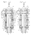
- the drive unit 6 has a drive unit 5 with a closed pressure medium circuit, which has a series of pump units, each with a hydraulic pump 39 flanged to an electric motor 38, each of which has a connecting line 40 with a hydraulic motor 41 and a connecting line 42 with a pressure medium container 43 connected is.
- the support shaft 3, which is driven by the hydraulic motors 41 via a gear 44, is mounted concentrically in the drive unit 5 on the one hand in a bearing 57 of the support plate 17 and on the other hand in a bearing 56 of the cover plate.
- the drive unit 5 has an outer jacket wall 47 connecting the support plate 17 to the cover plate and an inner wall 46 which is concentric with the latter and which is elastically cushioned against the support plate 17 and the cover plate by prestressed spring devices.
- the Pump units are in each case attached to the inner wall 46 distributed over their circumference in the annular space between the latter and the casing wall 47 via supporting projections 48 and elastic support elements 49. Also arranged in the annular space 45 is a water pump 51 which is connected to an electric motor 50 and which draws in ambient water via a suction opening 52 and a filter sieve 52a and feeds it to a purpose explained below by increasing the pressure via a connecting line 53.
- the electric motors 38 and 50 are each supplied with electrical energy from the work ship 7 via electrical lines 54 and 55 contained in the umbilical 16.
- all electric motors 38 and 50 are each connected to a flanged pressure water pump 79, which draws in ambient water via the suction opening 80 and the filter sieve 80a and the pressure water via the connecting lines 81 and 40 to the hydraulic motors 41 for driving the Leading shaft 3 supplies via the gear 44.
- the pressurized water then emerges freely from the outlet port 82 into the environment, so that there is an overall pressure medium circuit that is open to the environment.
- the electric motors 38 and 50 are supplied with electrical energy via the electrical lines 54 and 55 guided in the umbilical 16.
- the support shaft 3 is additionally mounted centrally in a bearing 58 arranged on the protective tube 4 near its lower end and connected at its free end to an exchangeably fastened tool carrier 2 which tapers on the underside and there with cutting edges 59 is provided.
- Clamping jaws 61 are pivotally mounted in lateral openings of the protective tube 4 and can be pressed against the inner wall of the pile 8 by associated hydraulic cylinders 62.
- the tool carrier 2 is driven during the insertion of the protective tube 4 into the pile 8 via the support shaft 3 in the manner of a drill in order to release the settled sediments by means of the cutting edges 59.
- pressurized water can be led down from the water pump 51 to the tool carrier 2 via a connecting line 53, in order to soften the sediments and, after loosening, flush them out upwards out of the pile 8 via the through-channel 60 of the tubular supporting shaft 3.
- the propulsive force required for the penetration is caused by the weight of the implement.
- the clamping jaws 61 Since no large torques occur when the layers of sediment are peeled off, the clamping jaws 61 only need to be slightly pressed against the inner wall of the pile in order to prevent the implement 1 and thus also the umbilical 16 and the supporting cables 6 or 24 and 25 from being twisted, so that they Although the low torque is absorbed by friction, on the other hand the implement 1 can sag automatically under its own weight in accordance with the progress of penetration. If a firmer frictional connection is required, the clamping jaws 61 can of course also be released briefly each time while the supporting shaft 3 is stopped and, after the implement 1 has sagged, can be pressed back onto the inner wall of the pile 8.
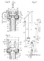
- a tool slide 64 is slidably guided in a horizontal guide.
- a cutting tool 65 shown only schematically in FIG. 8 and designed as cutting steel, is attached to the tool slide 64 and produces the desired separating cut in the wall of the pile 8 when the supporting shaft 3 and the tool carrier 2 are rotated.
- the cutting tool 65 can be infinitely adjusted by moving the tool carriage 64 by means of a hydraulic actuating cylinder 66 in order to appropriately adjust the chip thickness in accordance with the processing progress.
- a plurality of underwater cameras 63 are arranged on the inside of the protective tube 4 on the inside over its circumference. Instead, an underwater camera attached to the support shaft 3 or to the tool carrier 2 and rotating with it can also be provided.
- the supply lines of the underwater cameras which are not shown in FIG. 8 for reasons of clarity, can run on the inner wall of the protective tube 4 or via the supporting shaft 3 and a conventional slip ring rotary connection to the drive unit 5.
- a tool slide 67 which is adjustable in a horizontal guide by means of a hydraulic actuating cylinder 78 and which carries an underwater gas flame cutting torch 77, is mounted on the tool carrier 2 provided with conical cutting edges 59.
- the actuating cylinder 78 is fastened to a support block 68, on which a further actuating cylinder 69 for a second tool slide 70 is attached.
- This carries a drilling device 71 with a drilling tool 72 driven by a hydraulic motor 73.
- the drilling device 71 which is driven via pressure medium lines 74 and 75 running in the passage 60 of the supporting shaft 3, is used to create a hole 76 in the wall of the pile 8, that facilitates the approach of the cutting flame to the cut.
- the cutting torch 77 is supplied with fuel gas via a supply line 102 from a gas container carried on the drive unit 5 but not shown.
- cutting and firing tools can also be used, for example for liquid pressure jet cutting with a high-pressure water jet which may be enriched with abrasion particles, or for electric consumable burn-off.
- the pressure medium is supplied from a power station over water via a supply line 83, a distributor 85 and connecting lines 86 and 87 to the hydraulic motors 41 and then flows via the connecting lines 88 and 89 Distributor 85 and a supply line 84 back to a pressure medium tank over water.
- the connecting lines 87 and 88 can be shut off by the valve device 90 as needed to shut down the drive.
- the support plate 17 provided on its underside with pressure cylinders 18 and as segments of the insertion cone 13 is firmly connected via a spacer ring 95 by screws 96 to a support plate 91 and in turn carries the protective tube 4 on its underside.
- the support plate 17 arranged bearings 56 and 57 prevent 3 vertical displacements in cooperation with an annular collar 101 of the supporting shaft.
- the transmission 44 which is only shown schematically, is driven directly by electric motors 97.
- the extension tube 36 enclosing the electric motors 97 or a compensator 23 according to FIG. 4, the outer diameter of which can be adapted to the respective requirements.
- the electric motors 97 are driven via the umbilical 16, the distributor 98 and connecting lines 99 and 100.
- the implement 1 hanging on the suspension cable 6 of the crane 12 of a work ship 7 according to FIG. 10 is lowered with the conical tool carrier 2 into the opening of the pile 8, which is guided in a pile holder 9 at the foot of an oil rig leg 10 is.
- an electro-hydraulic underwater drive unit 5 of the type shown in FIG. 6 hangs on a further suspension cable 94 of the crane 12, the hydraulic pumps 39 of which are connected to the distributor of the implement 1 via connecting lines 92.
- the drive unit 5 is supplied with electrical energy by the work ship 7 via the umbilical 16.
- the short design of the implement 1 also makes the last one relatively short Pile guide 93 above the pile holder 9 still allows insertion of the implement into the pile 8. This mode of operation is advantageous in many cases despite the separate lowering of the drive unit 5 required.
Landscapes
- Engineering & Computer Science (AREA)
- Life Sciences & Earth Sciences (AREA)
- Mining & Mineral Resources (AREA)
- Geology (AREA)
- General Life Sciences & Earth Sciences (AREA)
- Geochemistry & Mineralogy (AREA)
- Fluid Mechanics (AREA)
- Environmental & Geological Engineering (AREA)
- Physics & Mathematics (AREA)
- Paleontology (AREA)
- Civil Engineering (AREA)
- General Engineering & Computer Science (AREA)
- Structural Engineering (AREA)
- Placing Or Removing Of Piles Or Sheet Piles, Or Accessories Thereof (AREA)
- Earth Drilling (AREA)
- Physical Or Chemical Processes And Apparatus (AREA)
- Other Liquid Machine Or Engine Such As Wave Power Use (AREA)
- Drilling And Exploitation, And Mining Machines And Methods (AREA)
Priority Applications (5)
| Application Number | Priority Date | Filing Date | Title |
|---|---|---|---|
| EP87110888A EP0301113B1 (fr) | 1987-07-28 | 1987-07-28 | Dispositif pour sectionner des pieux tubulaires de fondation sous l'eau |
| DE8787110888T DE3778542D1 (de) | 1987-07-28 | 1987-07-28 | Vorrichtung zum abtrennen rohrfoermiger gruendungspfaehle unter wasser. |
| NO873377A NO170894C (no) | 1987-07-28 | 1987-08-12 | Innretning for aa adskille roerformede fundamentpaeler undervann |
| JP62254523A JPH0678620B2 (ja) | 1987-07-28 | 1987-10-07 | 水中における管状の基礎杭の切断方法および装置 |
| US07/133,903 US4856938A (en) | 1987-07-28 | 1987-12-15 | Method of and arrangement for separating tubular foundation piles under water |
Applications Claiming Priority (1)
| Application Number | Priority Date | Filing Date | Title |
|---|---|---|---|
| EP87110888A EP0301113B1 (fr) | 1987-07-28 | 1987-07-28 | Dispositif pour sectionner des pieux tubulaires de fondation sous l'eau |
Publications (2)
| Publication Number | Publication Date |
|---|---|
| EP0301113A1 true EP0301113A1 (fr) | 1989-02-01 |
| EP0301113B1 EP0301113B1 (fr) | 1992-04-22 |
Family
ID=8197158
Family Applications (1)
| Application Number | Title | Priority Date | Filing Date |
|---|---|---|---|
| EP87110888A Expired - Lifetime EP0301113B1 (fr) | 1987-07-28 | 1987-07-28 | Dispositif pour sectionner des pieux tubulaires de fondation sous l'eau |
Country Status (5)
| Country | Link |
|---|---|
| US (1) | US4856938A (fr) |
| EP (1) | EP0301113B1 (fr) |
| JP (1) | JPH0678620B2 (fr) |
| DE (1) | DE3778542D1 (fr) |
| NO (1) | NO170894C (fr) |
Cited By (1)
| Publication number | Priority date | Publication date | Assignee | Title |
|---|---|---|---|---|
| CN110374020A (zh) * | 2019-06-20 | 2019-10-25 | 安徽建开建设工程有限公司 | 钢筋混凝土桩柱水中焊割切除施工方法及其辅助用具 |
Families Citing this family (26)
| Publication number | Priority date | Publication date | Assignee | Title |
|---|---|---|---|---|
| GB9604917D0 (en) * | 1996-03-08 | 1996-05-08 | Red Baron Oil Tools Rental | Removal of wellhead assemblies |
| DE19620756A1 (de) * | 1996-05-23 | 1997-11-27 | Wirth Co Kg Masch Bohr | Verfahren und Vorrichtung zum Abtrennen von im Boden verankerten Rohren oder Pfeilern |
| US6102884A (en) | 1997-02-07 | 2000-08-15 | Squitieri; Rafael | Squitieri hemodialysis and vascular access systems |
| US6629565B2 (en) | 2000-07-24 | 2003-10-07 | Smith International, Inc. | Abandonment and retrieval apparatus and method |
| GB2373266B (en) * | 2001-03-13 | 2004-08-18 | Sondex Ltd | Apparatus for anchoring a tool within a tubular |
| US20050137614A1 (en) * | 2003-10-08 | 2005-06-23 | Porter Christopher H. | System and method for connecting implanted conduits |
| US7762977B2 (en) * | 2003-10-08 | 2010-07-27 | Hemosphere, Inc. | Device and method for vascular access |
| GB2438349B (en) * | 2005-03-29 | 2009-12-16 | Norse Cutting & Abandonment As | A method and a device for attaching a subsea cutting apparatus |
| US7258597B2 (en) * | 2005-11-09 | 2007-08-21 | Oceaneering International, Inc. | Subsea abrasive jet cutting system and method of use |
| US20080028619A1 (en) * | 2006-06-23 | 2008-02-07 | The Stanley Works | Heavy duty material processing shears |
| US20070296229A1 (en) * | 2006-06-23 | 2007-12-27 | The Stanley Works | Grappling system |
| GB2448358B (en) * | 2007-04-12 | 2009-07-08 | Tidal Generation Ltd | Installation of underwater ground anchorages |
| US20110295181A1 (en) | 2008-03-05 | 2011-12-01 | Hemosphere, Inc. | Implantable and removable customizable body conduit |
| EP2265300B1 (fr) | 2008-03-05 | 2016-05-04 | CryoLife, Inc. | Système d'accès vasculaire |
| NL2003656C2 (nl) * | 2009-10-16 | 2011-04-19 | Ihc Holland Ie Bv | Samenstel van telescopische buisdelen. |
| EP2395156A1 (fr) * | 2010-06-08 | 2011-12-14 | IHC Holland IE B.V. | Procédé et système d'installation d'éléments de fondation dans une formation de sol sous-marin |
| DE102011052399B4 (de) | 2011-08-04 | 2014-11-13 | Aker Wirth Gmbh | Verfahren und Vorrichtung zum Abtrennen von Rohren |
| WO2013036643A2 (fr) | 2011-09-06 | 2013-03-14 | Hemosphere, Inc. | Système d'accès vasculaire doté d'un connecteur |
| NL2008279C2 (en) * | 2012-02-13 | 2013-08-14 | Ihc Holland Ie Bv | A template for and method of installing a plurality of foundation elements in an underwater ground formation. |
| EP2703564B1 (fr) * | 2012-08-30 | 2016-04-27 | BAUER Maschinen GmbH | Cadre de guidage pour guider un dispositif de fraisage |
| CA2927803C (fr) | 2013-12-20 | 2021-12-28 | Cryolife, Inc. | Systeme d'acces vasculaire ayant un element de renforcement |
| US9464399B2 (en) * | 2014-01-28 | 2016-10-11 | Ats Smart Solutions, Llc | Pile cutter |
| EP3568173A4 (fr) | 2017-01-12 | 2020-11-25 | Merit Medical Systems, Inc. | Procédés et systèmes de sélection et d'utilisation de raccords entre des conduits |
| US11590010B2 (en) | 2017-01-25 | 2023-02-28 | Merit Medical Systems, Inc. | Methods and systems for facilitating laminar flow between conduits |
| US10925710B2 (en) | 2017-03-24 | 2021-02-23 | Merit Medical Systems, Inc. | Subcutaneous vascular assemblies for improving blood flow and related devices and methods |
| CN106836223B (zh) * | 2017-04-11 | 2022-06-21 | 国强建设集团有限公司 | 一种拔桩方法 |
Citations (3)
| Publication number | Priority date | Publication date | Assignee | Title |
|---|---|---|---|---|
| DE342498C (fr) * | ||||
| US3338305A (en) * | 1965-02-05 | 1967-08-29 | Halliburton Co | Method and apparatus for cutting casing in underwater installations |
| JPS56159426A (en) * | 1980-05-14 | 1981-12-08 | Shoei:Kk | Steel pipe cutter |
Family Cites Families (5)
| Publication number | Priority date | Publication date | Assignee | Title |
|---|---|---|---|---|
| US2622679A (en) * | 1948-10-08 | 1952-12-23 | Russell A Ransom | Inside pipe cutter |
| US3396795A (en) * | 1966-09-09 | 1968-08-13 | Dresser Ind | Tubing cutter |
| US4339008A (en) * | 1980-06-09 | 1982-07-13 | D. B. D. Drilling, Inc. | Well notching tool |
| JPS6043493A (ja) * | 1983-08-19 | 1985-03-08 | Chiyoda Kagaku Kenkyusho:Kk | 銅の変色防止剤 |
| US4768899A (en) * | 1987-04-20 | 1988-09-06 | Dysarz Edward D | Device and method to cut piles |
-
1987
- 1987-07-28 EP EP87110888A patent/EP0301113B1/fr not_active Expired - Lifetime
- 1987-07-28 DE DE8787110888T patent/DE3778542D1/de not_active Expired - Fee Related
- 1987-08-12 NO NO873377A patent/NO170894C/no not_active IP Right Cessation
- 1987-10-07 JP JP62254523A patent/JPH0678620B2/ja not_active Expired - Lifetime
- 1987-12-15 US US07/133,903 patent/US4856938A/en not_active Expired - Fee Related
Patent Citations (3)
| Publication number | Priority date | Publication date | Assignee | Title |
|---|---|---|---|---|
| DE342498C (fr) * | ||||
| US3338305A (en) * | 1965-02-05 | 1967-08-29 | Halliburton Co | Method and apparatus for cutting casing in underwater installations |
| JPS56159426A (en) * | 1980-05-14 | 1981-12-08 | Shoei:Kk | Steel pipe cutter |
Non-Patent Citations (4)
| Title |
|---|
| BAUMASCHINE & BAUTECHNIK, BMT, Band 30, Nr. 10, Oktober 1983, Seiten 476-483, Wiesbaden, DE; H. KÜHN: "Entwicklungen in der Unterwasser-Rammtechnik" * |
| PATENT ABSTRACTS OF JAPAN, Band 10, Nr. 261 (M-514)[2317], 5. September 1986; & JP-A-61 87 020 (NIPPON KOKAN K.K.) 02-05-1986 * |
| PATENT ABSTRACTS OF JAPAN, Band 10, Nr. 368 (M-543)[2425], 9. Dezember 1986; & JP-A-61 162 637 (HAZAMA GUMI LTD) 23-07-1986 * |
| PATENT ABSTRACTS OF JAPAN, Band 11, Nr. 74 (M-568)[2521], 6. März 1987; & JP-A-61 229 022 (NIPPON STEEL CORP.) 13-10-1986 * |
Cited By (1)
| Publication number | Priority date | Publication date | Assignee | Title |
|---|---|---|---|---|
| CN110374020A (zh) * | 2019-06-20 | 2019-10-25 | 安徽建开建设工程有限公司 | 钢筋混凝土桩柱水中焊割切除施工方法及其辅助用具 |
Also Published As
| Publication number | Publication date |
|---|---|
| JPH01102127A (ja) | 1989-04-19 |
| DE3778542D1 (de) | 1992-05-27 |
| NO873377L (no) | 1989-01-30 |
| EP0301113B1 (fr) | 1992-04-22 |
| NO170894B (no) | 1992-09-14 |
| NO873377D0 (no) | 1987-08-12 |
| NO170894C (no) | 1992-12-23 |
| US4856938A (en) | 1989-08-15 |
| JPH0678620B2 (ja) | 1994-10-05 |
Similar Documents
| Publication | Publication Date | Title |
|---|---|---|
| EP0301113B1 (fr) | Dispositif pour sectionner des pieux tubulaires de fondation sous l'eau | |
| DE69824738T2 (de) | Kerngewinnung im meeresboden mit hilfe eines kolbens | |
| EP0301114B1 (fr) | Procédé pour enfoncer des éléments battus sous l'eau | |
| DE3047375A1 (de) | "tauchfaehige rammvorrichtung" | |
| EP2322724B1 (fr) | Installation de forage d'eau souterraine et procédé d'entrée d'un élément de fondation cylindrique au fond de l'eau | |
| EP0301116B1 (fr) | Unité de commande électrohydraulique immergeable pour appareils de battage et de service mis en oeuvre sous l'eau | |
| DE1298472B (de) | Einrichtung zum Ziehen und Nachlassen des Bohrgestaenges in Bohrtuermen oder Bohrinseln | |
| DE2644725A1 (de) | Bohrinsel | |
| DE2006572A1 (de) | Rammverfahren, Vorrichtung zum Eintreiben eines Ankers, eines Pfahles oder dergleichen in die Erde und Anker- und Pfahl-Einrichtung | |
| DE19620756A1 (de) | Verfahren und Vorrichtung zum Abtrennen von im Boden verankerten Rohren oder Pfeilern | |
| EP2093373B1 (fr) | Dispositif de forage, en particulier pour l'établissement de trous de mine sur le sol d'un cours d'eau, et procédé d'introduction d'une charge d'explosif dans le sol d'un cours d'eau | |
| DE2342566B2 (de) | Verfahren zum Abtragen einer abgesetzten, teilchenförmigen Feststoffmasse | |
| EP0263967B1 (fr) | Dispositif de battage immergeable | |
| DE1932230C3 (de) | Unterwasseranlage zum Anschließen an mindestens eine Unterwassertiefbohrung | |
| EP0928876A1 (fr) | Dispositif de forage d'un trou en terre | |
| EP3330441B1 (fr) | Dispositif de réduction d'eau d'aval et procédé de réduction | |
| DE1925912B2 (de) | Vorrichtung zum Herabziehen eines Unterwasser-Standrohres von einer schwimmenden Plattform zu einem Unterwasser-Bohrlochkopf | |
| EP0819819A1 (fr) | Tête de fraisage, dispositif de forage et procédé de forage sous-marin | |
| DE102012218285A1 (de) | Vorrichtung und Verfahren zum Erstellen einer Gründung und Gründung | |
| DE1178026B (de) | Verfahren und Vorrichtung zum Durchfuehren von Arbeiten an Unterwasser-Tiefbohrungen | |
| DE2537918A1 (de) | Verfahren zum abweisen von eis an senkrecht im wasser stehenden saeulen von in eisgefaerdeten seegebieten fest angeordneten oder schwimmenden bauwerken und eine eisabweisende einrichtung hierfuer | |
| EP0312619A1 (fr) | Dispositif de coupe pour couper des éléments de construction tubulaires | |
| DE2947211A1 (de) | Fuehrungsvorrichtung fuer eine taucherglocke | |
| DE3525725C2 (fr) | ||
| DE1634430A1 (de) | Verfahren zum Ziehen einer Grundprobe sowie Vorrichtung zur Anwendung dieses Verfahrens Koninklijke Maatschappij tot het uitroeren van openbare werken |
Legal Events
| Date | Code | Title | Description |
|---|---|---|---|
| PUAI | Public reference made under article 153(3) epc to a published international application that has entered the european phase |
Free format text: ORIGINAL CODE: 0009012 |
|
| 17P | Request for examination filed |
Effective date: 19880831 |
|
| AK | Designated contracting states |
Kind code of ref document: A1 Designated state(s): DE FR GB IT NL SE |
|
| 17Q | First examination report despatched |
Effective date: 19900222 |
|
| RAP1 | Party data changed (applicant data changed or rights of an application transferred) |
Owner name: MENCK GMBH |
|
| GRAA | (expected) grant |
Free format text: ORIGINAL CODE: 0009210 |
|
| AK | Designated contracting states |
Kind code of ref document: B1 Designated state(s): DE FR GB IT NL SE |
|
| PG25 | Lapsed in a contracting state [announced via postgrant information from national office to epo] |
Ref country code: IT Free format text: LAPSE BECAUSE OF FAILURE TO SUBMIT A TRANSLATION OF THE DESCRIPTION OR TO PAY THE FEE WITHIN THE PRE;WARNING: LAPSES OF ITALIAN PATENTS WITH EFFECTIVE DATE BEFORE 2007 MAY HAVE OCCURRED AT ANY TIME BEFORE 2007. THE CORRECT EFFECTIVE DATE MAY BE DIFFERENT FROM THE ONE RECORDED.SCRIBED TIME-LIMIT Effective date: 19920422 Ref country code: FR Effective date: 19920422 Ref country code: SE Effective date: 19920422 |
|
| REF | Corresponds to: |
Ref document number: 3778542 Country of ref document: DE Date of ref document: 19920527 |
|
| GBT | Gb: translation of ep patent filed (gb section 77(6)(a)/1977) | ||
| EN | Fr: translation not filed | ||
| PLBE | No opposition filed within time limit |
Free format text: ORIGINAL CODE: 0009261 |
|
| STAA | Information on the status of an ep patent application or granted ep patent |
Free format text: STATUS: NO OPPOSITION FILED WITHIN TIME LIMIT |
|
| 26N | No opposition filed | ||
| NLS | Nl: assignments of ep-patents |
Owner name: MENCK GMBH |
|
| NLT1 | Nl: modifications of names registered in virtue of documents presented to the patent office pursuant to art. 16 a, paragraph 1 |
Owner name: BOMAG-BETEILIGUNGS-GMBH |
|
| REG | Reference to a national code |
Ref country code: GB Ref legal event code: 732E |
|
| PGFP | Annual fee paid to national office [announced via postgrant information from national office to epo] |
Ref country code: NL Payment date: 20000703 Year of fee payment: 14 Ref country code: GB Payment date: 20000703 Year of fee payment: 14 Ref country code: DE Payment date: 20000703 Year of fee payment: 14 |
|
| PG25 | Lapsed in a contracting state [announced via postgrant information from national office to epo] |
Ref country code: GB Free format text: LAPSE BECAUSE OF NON-PAYMENT OF DUE FEES Effective date: 20010728 |
|
| PG25 | Lapsed in a contracting state [announced via postgrant information from national office to epo] |
Ref country code: NL Free format text: LAPSE BECAUSE OF NON-PAYMENT OF DUE FEES Effective date: 20020201 |
|
| GBPC | Gb: european patent ceased through non-payment of renewal fee |
Effective date: 20010728 |
|
| NLV4 | Nl: lapsed or anulled due to non-payment of the annual fee |
Effective date: 20020201 |
|
| PG25 | Lapsed in a contracting state [announced via postgrant information from national office to epo] |
Ref country code: DE Free format text: LAPSE BECAUSE OF NON-PAYMENT OF DUE FEES Effective date: 20020501 |