EP0301189B1 - Verfahren und Vorrichtung zum Herstellen eines Rippen-Rohres aus Kunststoff - Google Patents
Verfahren und Vorrichtung zum Herstellen eines Rippen-Rohres aus Kunststoff Download PDFInfo
- Publication number
- EP0301189B1 EP0301189B1 EP88108096A EP88108096A EP0301189B1 EP 0301189 B1 EP0301189 B1 EP 0301189B1 EP 88108096 A EP88108096 A EP 88108096A EP 88108096 A EP88108096 A EP 88108096A EP 0301189 B1 EP0301189 B1 EP 0301189B1
- Authority
- EP
- European Patent Office
- Prior art keywords
- moulding
- production
- tube
- fins
- chamber
- Prior art date
- Legal status (The legal status is an assumption and is not a legal conclusion. Google has not performed a legal analysis and makes no representation as to the accuracy of the status listed.)
- Expired - Lifetime
Links
- 238000004519 manufacturing process Methods 0.000 title claims description 38
- 229920003023 plastic Polymers 0.000 title claims description 24
- 239000004033 plastic Substances 0.000 title claims description 24
- 238000000034 method Methods 0.000 title claims description 7
- 238000000465 moulding Methods 0.000 claims description 35
- 238000001816 cooling Methods 0.000 claims description 11
- 230000007704 transition Effects 0.000 claims description 8
- 239000000463 material Substances 0.000 claims description 7
- 238000013022 venting Methods 0.000 claims description 3
- 238000010276 construction Methods 0.000 claims 1
- 239000013589 supplement Substances 0.000 claims 1
- 238000011144 upstream manufacturing Methods 0.000 claims 1
- 239000007921 spray Substances 0.000 description 21
- 239000000155 melt Substances 0.000 description 7
- 230000000694 effects Effects 0.000 description 6
- 239000000498 cooling water Substances 0.000 description 4
- 239000007788 liquid Substances 0.000 description 3
- 238000009423 ventilation Methods 0.000 description 3
- 230000000295 complement effect Effects 0.000 description 2
- 238000009413 insulation Methods 0.000 description 2
- 241001125292 Balaena mysticetus Species 0.000 description 1
- 230000004323 axial length Effects 0.000 description 1
- 238000002347 injection Methods 0.000 description 1
- 239000007924 injection Substances 0.000 description 1
- 229920000642 polymer Polymers 0.000 description 1
- 239000000256 polyoxyethylene sorbitan monolaurate Substances 0.000 description 1
- 239000004800 polyvinyl chloride Substances 0.000 description 1
- 239000000243 solution Substances 0.000 description 1
- 238000005507 spraying Methods 0.000 description 1
Images



Classifications
-
- B—PERFORMING OPERATIONS; TRANSPORTING
- B29—WORKING OF PLASTICS; WORKING OF SUBSTANCES IN A PLASTIC STATE IN GENERAL
- B29C—SHAPING OR JOINING OF PLASTICS; SHAPING OF MATERIAL IN A PLASTIC STATE, NOT OTHERWISE PROVIDED FOR; AFTER-TREATMENT OF THE SHAPED PRODUCTS, e.g. REPAIRING
- B29C48/00—Extrusion moulding, i.e. expressing the moulding material through a die or nozzle which imparts the desired form; Apparatus therefor
- B29C48/25—Component parts, details or accessories; Auxiliary operations
- B29C48/88—Thermal treatment of the stream of extruded material, e.g. cooling
- B29C48/90—Thermal treatment of the stream of extruded material, e.g. cooling with calibration or sizing, i.e. combined with fixing or setting of the final dimensions of the extruded article
- B29C48/908—Thermal treatment of the stream of extruded material, e.g. cooling with calibration or sizing, i.e. combined with fixing or setting of the final dimensions of the extruded article characterised by calibrator surface, e.g. structure or holes for lubrication, cooling or venting
-
- B—PERFORMING OPERATIONS; TRANSPORTING
- B29—WORKING OF PLASTICS; WORKING OF SUBSTANCES IN A PLASTIC STATE IN GENERAL
- B29C—SHAPING OR JOINING OF PLASTICS; SHAPING OF MATERIAL IN A PLASTIC STATE, NOT OTHERWISE PROVIDED FOR; AFTER-TREATMENT OF THE SHAPED PRODUCTS, e.g. REPAIRING
- B29C48/00—Extrusion moulding, i.e. expressing the moulding material through a die or nozzle which imparts the desired form; Apparatus therefor
- B29C48/03—Extrusion moulding, i.e. expressing the moulding material through a die or nozzle which imparts the desired form; Apparatus therefor characterised by the shape of the extruded material at extrusion
- B29C48/09—Articles with cross-sections having partially or fully enclosed cavities, e.g. pipes or channels
-
- B—PERFORMING OPERATIONS; TRANSPORTING
- B29—WORKING OF PLASTICS; WORKING OF SUBSTANCES IN A PLASTIC STATE IN GENERAL
- B29C—SHAPING OR JOINING OF PLASTICS; SHAPING OF MATERIAL IN A PLASTIC STATE, NOT OTHERWISE PROVIDED FOR; AFTER-TREATMENT OF THE SHAPED PRODUCTS, e.g. REPAIRING
- B29C48/00—Extrusion moulding, i.e. expressing the moulding material through a die or nozzle which imparts the desired form; Apparatus therefor
- B29C48/03—Extrusion moulding, i.e. expressing the moulding material through a die or nozzle which imparts the desired form; Apparatus therefor characterised by the shape of the extruded material at extrusion
- B29C48/13—Articles with a cross-section varying in the longitudinal direction, e.g. corrugated pipes
-
- B—PERFORMING OPERATIONS; TRANSPORTING
- B29—WORKING OF PLASTICS; WORKING OF SUBSTANCES IN A PLASTIC STATE IN GENERAL
- B29C—SHAPING OR JOINING OF PLASTICS; SHAPING OF MATERIAL IN A PLASTIC STATE, NOT OTHERWISE PROVIDED FOR; AFTER-TREATMENT OF THE SHAPED PRODUCTS, e.g. REPAIRING
- B29C48/00—Extrusion moulding, i.e. expressing the moulding material through a die or nozzle which imparts the desired form; Apparatus therefor
- B29C48/25—Component parts, details or accessories; Auxiliary operations
- B29C48/30—Extrusion nozzles or dies
- B29C48/303—Extrusion nozzles or dies using dies or die parts movable in a closed circuit, e.g. mounted on movable endless support
-
- B—PERFORMING OPERATIONS; TRANSPORTING
- B29—WORKING OF PLASTICS; WORKING OF SUBSTANCES IN A PLASTIC STATE IN GENERAL
- B29C—SHAPING OR JOINING OF PLASTICS; SHAPING OF MATERIAL IN A PLASTIC STATE, NOT OTHERWISE PROVIDED FOR; AFTER-TREATMENT OF THE SHAPED PRODUCTS, e.g. REPAIRING
- B29C48/00—Extrusion moulding, i.e. expressing the moulding material through a die or nozzle which imparts the desired form; Apparatus therefor
- B29C48/25—Component parts, details or accessories; Auxiliary operations
- B29C48/88—Thermal treatment of the stream of extruded material, e.g. cooling
- B29C48/90—Thermal treatment of the stream of extruded material, e.g. cooling with calibration or sizing, i.e. combined with fixing or setting of the final dimensions of the extruded article
- B29C48/901—Thermal treatment of the stream of extruded material, e.g. cooling with calibration or sizing, i.e. combined with fixing or setting of the final dimensions of the extruded article of hollow bodies
- B29C48/902—Thermal treatment of the stream of extruded material, e.g. cooling with calibration or sizing, i.e. combined with fixing or setting of the final dimensions of the extruded article of hollow bodies internally
-
- B—PERFORMING OPERATIONS; TRANSPORTING
- B29—WORKING OF PLASTICS; WORKING OF SUBSTANCES IN A PLASTIC STATE IN GENERAL
- B29C—SHAPING OR JOINING OF PLASTICS; SHAPING OF MATERIAL IN A PLASTIC STATE, NOT OTHERWISE PROVIDED FOR; AFTER-TREATMENT OF THE SHAPED PRODUCTS, e.g. REPAIRING
- B29C2791/00—Shaping characteristics in general
- B29C2791/004—Shaping under special conditions
- B29C2791/006—Using vacuum
-
- B—PERFORMING OPERATIONS; TRANSPORTING
- B29—WORKING OF PLASTICS; WORKING OF SUBSTANCES IN A PLASTIC STATE IN GENERAL
- B29C—SHAPING OR JOINING OF PLASTICS; SHAPING OF MATERIAL IN A PLASTIC STATE, NOT OTHERWISE PROVIDED FOR; AFTER-TREATMENT OF THE SHAPED PRODUCTS, e.g. REPAIRING
- B29C48/00—Extrusion moulding, i.e. expressing the moulding material through a die or nozzle which imparts the desired form; Apparatus therefor
- B29C48/001—Combinations of extrusion moulding with other shaping operations
- B29C48/0018—Combinations of extrusion moulding with other shaping operations combined with shaping by orienting, stretching or shrinking, e.g. film blowing
-
- B—PERFORMING OPERATIONS; TRANSPORTING
- B29—WORKING OF PLASTICS; WORKING OF SUBSTANCES IN A PLASTIC STATE IN GENERAL
- B29K—INDEXING SCHEME ASSOCIATED WITH SUBCLASSES B29B, B29C OR B29D, RELATING TO MOULDING MATERIALS OR TO MATERIALS FOR MOULDS, REINFORCEMENTS, FILLERS OR PREFORMED PARTS, e.g. INSERTS
- B29K2995/00—Properties of moulding materials, reinforcements, fillers, preformed parts or moulds
- B29K2995/0037—Other properties
- B29K2995/0072—Roughness, e.g. anti-slip
-
- B—PERFORMING OPERATIONS; TRANSPORTING
- B29—WORKING OF PLASTICS; WORKING OF SUBSTANCES IN A PLASTIC STATE IN GENERAL
- B29L—INDEXING SCHEME ASSOCIATED WITH SUBCLASS B29C, RELATING TO PARTICULAR ARTICLES
- B29L2023/00—Tubular articles
- B29L2023/003—Tubular articles having irregular or rough surfaces
Definitions
- the invention relates to a method according to the preamble of claim 1 and to a device according to the preamble of claim 3.
- a method of the generic type is known from EP 0 005 104 A1.
- the intended fins are formed one after the other in a moving direction in the production direction - the molding space in the production direction - by the entry of plastic melt into the molding space and a tube is formed which is integral with the fins.
- the ribs and the constrictions arranged between them have a longitudinal contour, which is characterized by semicircular delimitation lines that are continuously lined up. Filling the rib shape recesses with plastic melt is undefined.
- the spray mandrel extends a relatively long distance in the direction of production up to the nozzle gap.
- this expansion space which is formed by the cone-shaped expanding mandrel and the mold recess, there are numerous rib-shaped recesses, the filling of which is undefined. Furthermore, a safe transport of the hose with ribs through the molding space is not guaranteed.
- DE-C-24 50 171 discloses a device similar to the generic device, in which the molding space adjoins a melt channel. At the end of the molding space there is a spray mandrel which widens in the shape of a truncated cone and by means of which the pipe is calibrated. Here too, the rib shape recesses are filled undefined. In addition, there is a great risk that melt will penetrate and burn in the area between the nozzle and the mold recess.
- the invention has for its object to develop a method of the generic type so that an exact filling of the rib-shaped recesses and thus an exact contour of the pipe to be produced is achieved.
- Claim 2 specifies an advantageous embodiment of the method described above.
- the solution according to the invention in the generic device according to claim 3 ensures that the elevations on the hose are formed and that the hose is taken along.
- the embodiment according to claim 4 ensures that there is no excess pressure in the expansion space which could push the melt back into the gap between the nozzle and the mold recess, which is also prevented there anyway by the conveying grooves in the half molds.
- the embodiment according to claim 5 promotes the effects specified above.
- the measures according to claim 6 ensure that the calibration of the inner wall of the hose and thus of the later pipe only takes place at a relatively late point in time when the ribs have already been reliably formed.
- the device for producing plastic finned tubes has a machine table 1 on which half molds 2, 2 'are arranged, each of which is connected to one another to form so-called chains 3 and 3'.
- a tab 5 is attached to each half mold 2 or 2 'on its outer area, which is at the front in the direction of production 4, by means of an attachment.
- Steering pin 6 articulated, which is also attached at the corresponding point of the subsequent half mold 2 or 2 'by means of such a pivot pin 6.
- the chains 3, 3 'formed in this way are guided at their rear end, viewed in the direction of production 4, via deflection wheels serving as so-called entry rollers 7.
- the individual half molds 2, 2' are pivoted into a molding section 9 according to the direction of rotation arrows 8 and 8 ', in which two half molds 2, 2' are combined to form a pair of molds, again in Production direction 4 successive pairs of molds lie close together.
- so-called closing rollers 10 are provided, which accelerate the rear ends of the half molds 2, 2' in the direction of production 4.
- the adjacent half molds 2, 2 ' are pressed against one another by means of guide rollers 11 which are rotatably mounted in guide strips 12.
- the feed rollers 7 are attached to the machine table 1 so as to be rotatable about journal 13.
- return rollers 14 which also serve as deflection wheels, are rotatably mounted about axle journals 15, around which the chains 3 or 3 ′ are deflected and returned to the inlet rollers 7.
- the guide strips 12 with guide rollers 11 already end in front of the return rollers 14 by the length of several half molds 2 or 2 ', so that the half molds 2 or 2' again move parallel to one another and transversely to the direction of production 4 can be pivoted before the return rollers 14.
- a toothing 16 is formed on the upper side of the half molds 2, 2 ', the two toothings 16 of the half molds 2, 2', which are assigned to one another in pairs, being flush with one another, so that a common drive pinion 17 can engage in this toothing 16 from above pushes the half molds 2,2 'as a closed mold through the molding section 9.
- This drive pinion 17 is driven in the usual way by a motor (not shown) via a drive gearwheel 18 which is fixed in a rotationally fixed manner on a shaft 19 which in turn carries the drive pinion 17.
- the shaft 19 is mounted in a bearing block 20, which is supported via distance prisms 21 with respect to the machine table and is fixedly connected to the latter by means of screws 22.
- plastic pipes 23 with ribs 24 extending radially and over the outer circumference of the pipes 23 as closed annular disks are produced.
- Such finned tubes have a particularly high crest pressure resistance.
- An extruder is provided, of which only the spray nozzle 25 is indicated, from which plastic melt 23a, which flows in the liquid state into the mold formed in the mold section 9, is extruded in a manner to be described in more detail below , in which the tube 23 is formed with the fins 24.
- the device described so far is known, with the exception of the special design of the tubes 23 with fins 24, for example from DE-PS 20 61 027 or EP-PS 0 065 729.
- the half molds 2, 2 'arranged in pairs are cooled.
- cooling water channels 26 are formed in them.
- the shaped recesses 28 formed in the half molds 2.2a to form a molding space 27 have a shape complementary to the outer shape of the tube 23 with ribs 24. At their radially outermost locations, they are provided with ventilation bores or slots 29 which open into ventilation channels 30. These are connected to partial vacuum sources, not shown, so that venting and complete filling of the molding space 27 with the plastic forming the tube 23 with ribs 24 is ensured.
- the spray nozzle 25 is surrounded in the region in which the half molds 2, 2 'are not yet completely closed to form a mold, with a heater 31, around which the compressed plastic melt 23a extruded from the extruder and conveyed through the spray nozzle 25 to maintain the required temperature. If polyvinyl chloride (PVC) is used as the plastic, this temperature is approximately 195 to 200 ° C. Shortly after the start of the molding section, ie shortly after the area at which the complementary half molds 2, 2 'lie firmly against one another, expands the outer circumference of the spray nozzle 25 to form a cylindrical end section 32. The corresponding half mold just in its closed position is designated 2a in the drawing.
- PVC polyvinyl chloride
- a safety gap 34 is provided between the radially inner side 33 of the half mold 2a and the cylindrical end section 32, which ensures that the half mold 2a does not come into contact with the cylindrical end section 32 of the spray nozzle 25.
- the width of the safety gap is therefore between 0.3 and 0.8 mm.
- a continuously expanding melt channel 35 is formed, which is delimited on the inside by a spray mandrel 36.
- the radial extent a is as possible no more than 1.5 times the minimum wall thickness b of the tube 23.
- the spray mandrel 36 has a first cone section 39 adjoining the nozzle gap 37, to which a second cone section 40 adjoins in the direction of production 4.
- the first cone section 39 forms an angle c of approximately 5 ° with the central longitudinal axis 41 of the spray nozzle 25 or the pipe 23 to be produced or the mold space 27.
- the second cone section 40 forms an angle d of approximately 3 ° with the axis 41.
- the transition 42 of the spray mandrel 36 in the region of the nozzle gap 37 into the first cone section 39 is rounded.
- the first cone section 39 and the second cone section 40 together form a bevel 43, to which a cylindrical section 44 of the injection mandrel 36 is also connected.
- a bracket head 45 is attached to the spraying mandrel 36, specifically on its cylindrical section 44.
- This is pot-shaped, i.e. it has a cylindrical recess 46 which is open in the direction of production 4 and is lined with a bell-shaped thermal insulation 47.
- Screw bolts 48 are used to fasten the stirrup head to the spray mandrel 36.
- the stirrup head 45 has, in the region adjoining the cylindrical section 44 of the spray mandrel 36, a conical section 49 which widens in the direction of production 4 and to which a cylindrical section is attached 50 connects.
- the cone section 49 forms an angle e to the axis 41 from 3 to 4.
- the spray mandrel 36 and with it the bracket head 45 fastened to it are attached to a spray mandrel holder 51 and held there by means of a ring nut 52 on a thread 53 of the spray mandrel holder 51.
- a cooling hollow mandrel 54, on which a cooling mandrel 55 is attached, is guided concentrically to the axis 41 by the spray mandrel holder 51.
- This cooling mandrel 55 can be cooled by cooling water which is fed in and out through the hollow mandrel 54.
- a corresponding cooling water inlet 71 and a cooling water outlet 72 are indicated in FIG. 2.
- the cooling mandrel 55 is cylindrical.
- the bow head 55 lies flat against the annular end face 57 of the spray mandrel 36.
- the cooling mandrel 55 rests with a matching surface 58 on the associated end face of the bracket head.
- the shaped recess 28 of the half molds 2.2a has an essentially cylindrical tube outer wall shape section 60 forming the radially inner side 33 of the corresponding half mold 2.2a, between which the ribs 24, which are used to form the ribs 24, are used at constant intervals - Gen 61 are arranged.
- the outer tube wall - shaped sections 60 have conveyor grooves 62 which extend around the full cylinder circumference of the shaped section 60 and which lead to corresponding ring elevations 63 on the outer tube wall.
- the conveyor grooves 62 are delimited on their respective rear sides - with respect to the production direction 4 - by a conveyor surface 64 which extends essentially radially to the axis 41. Its other boundary surface 65 extends flatly inclined to the axis 41 in the direction of the next conveying surface 64 of the next leading conveying groove 62 which leads in the production direction 4.
- a finned tube is essentially manufactured in three phases.
- the highly compressed plastic melt 23a is pressed through the nozzle gap 37 into the expansion space 38 at the beginning of the molding space 27.
- a rib 61 already in the direction of production 4 in front of the expansion space 38 is filled.
- the air in this is drawn off through the ventilation slots 29, which are so narrow that liquid melt cannot get into them.
- the expansion space 38 fills, since with a constant, constant production speed in the production direction 4, ie with a constant speed of the half molds 2a, the plastic melt 23a is only required to produce the cylindrical tube wall section of the tube 23.
- the ratio of the distance f between adjacent ribs 24, ie adjacent rib-shaped recesses 61, to the axial length g of the expansion space 38 is in the range from 1: 1 to 1: 1.5. In this area, in particular in the lower part of this area, it is ensured that the intensified conveyance of the plastic melt 23a through the conveying grooves 62 fills the individual ribs-shaped recesses 61 one after the other. At the end of this first phase there is already a tube 23.
- the second phase of forming the tube 23 takes place above the bracket head 45, which has a mirror-like surface in order to calibrate the still warm-plastic tube 23 so that it later has a clean, smooth inner wall 67.
- the tube 23 is partially cooled, and its surface area, for example 0.1 mm deep, is already cooled to 50 to 60 ° C.
- the third phase of the production of the tube 23 takes place over the cooling mandrel 55, on which the exact calibration of the tube 23 takes place.
- the cone section 49 of the bracket head 45 and the cone shoulder 56 of the cooling mandrel 55 each have the task of ensuring a seamless transition of the tube 23 at the corresponding transition point.
- FIGS. 7, 8 and 9 show different ring elevations 63 ', 63 ", 63"', to which adapted shape conveying grooves in the half mold 2a correspond.
- an annular elevation 63 ' is formed with a radially sloping conveying surface 68', which corresponds to a corresponding conveying surface as a limitation of the associated rib-shaped recess.
- This conveying surface 68 'thus runs approximately perpendicular to the central longitudinal axis 41 (not shown in FIGS. 7, 8 and 9).
- the transition to the gently sloping flank 69 ' is provided with a clear rounding 70. Due to this rounding 70, there is no notch effect in the corresponding conveying groove of the half mold 2a.
- the flank 69 ' is formed on the boundary surface 65 of the half mold.
- the transition from the conveying surface 68 "or 68 '" to the flank 69 "or 69"' is pointed. This leads to a correspondingly good conveying effect, but to a disadvantageous notching effect in the half mold 2a.
- the ring elevations 63 ′ ′′ are designed with a smaller radial height and at a smaller distance from one another.
- the ribs 24 have a radial height h - measured from the foot of the conveying surfaces 68 or flanks 69 - which is approximately 0.035 i, where i denotes the inside diameter of the tube 23.
- the minimum pipe wall thickness b corresponds to approximately 0.015 i.
- the height of the ring elevations 63 is approximately 0.12 b to 0.16 b.
Landscapes
- Engineering & Computer Science (AREA)
- Mechanical Engineering (AREA)
- Physics & Mathematics (AREA)
- Thermal Sciences (AREA)
- Manufacturing & Machinery (AREA)
- Moulds For Moulding Plastics Or The Like (AREA)
- Extrusion Moulding Of Plastics Or The Like (AREA)
- Casting Or Compression Moulding Of Plastics Or The Like (AREA)
- Shaping Of Tube Ends By Bending Or Straightening (AREA)
Description
- Die Erfindung bezieht sich auf ein Verfahren nach dem Oberbegriff des Anspruches 1 und auf eine Vorrichtung nach dem Oberbegriff des An - spruches 3.
- Aus der EP 0 005 104 A1 ist ein Verfahren der gattungsgemäßen Art bekannt. Dabei werden in einem sich in einer Produktionsrichtung bewegen - den Formraum in Produktionsrichtung hintereinan - der vorgesehene Rippen durch Eintritt von Kunststoff - Schmelze in den Formraum nachein - ander ausgeformt und ein mit den Rippen ein - stückiges Rohr gebildet. Die Rippen und die zwi - schen ihnen angeordneten Einschnürungen weisen eine Längskontur auf, die durch kontinuierlich an - einandergereihte halbkreisförmige Begrenzungsli - nien charakterisiert ist. Das Füllen der Rippen - Formausnehmungen mit Kunststoff - Schmelze er - folgt undefiniert. Insbesondere ist nicht gewährlei - stet, daß die Rippen - Formausnehmungen voll - ständig und blasenfrei mit Kunststoff - Schmelze ausgefüllt werden, da sich bei Eintreten der Kunststoffschmelze in die Rippen - Formausneh - mungen Blasen ausbilden können, die aufgrund des Formdruckes der Schmelze nicht mehr entweichen können.
- Aus der DE-A-23 46 444 ist eine Vorrichtung der gattungsgemäßen Art bekannt, auf der das gattungsgemäße Verfahren ausgeübt wird. Hierbei erstreckt sich der Spritzdorn ein relativ langes Stück in Produktionsrichtung bis vor den Düsen - spalt. Im Bereich dieses durch den sich kegel - stumpfförmig erweiternden Spritzdorn und die Formausnehmung gebildeten Expansionsraums befinden sich zahlreiche Rippen - Formausneh - mungen, deren Füllen undefiniert erfolgt. Des wei - teren ist ein sicherer Transport des Schlauches mit Rippen durch den Formraum nicht gewährleistet.
- Aus der DE - C - 24 50 171 ist eine der gattungsgemäßen Vorrichtung ähnliche Vorrichtung bekannt, bei der der Formraum sich an einen Schmelzekanal anschließt. Am Ende des Form - raums ist ein sich kegelstumpfförmig erweiternder Spritzdorn angebracht, mittels dessen eine Kali - brierung des Rohres erfolgt. Auch hier erfolgt das Füllen der Rippen - Formausnehmungen undefi - niert. Darüber hinaus ist die Gefahr groß, daß Schmelze in den Bereich zwischen Düse und Formausnehmung eindringt und verbrennt.
- Der Erfindung liegt die Aufgabe zugrunde, ein Verfahren der gattungsgemäßen Art so weiterzu - bilden, daß ein genaues Füllen der Rippen - Formausnehmungen und damit eine genaue Kontur des zu erzeugenden Rohres erreicht wird.
- Diese Aufgabe wird erfindungsgemäß durch die Merkmale des Anspruches 1 gelöst. Durch die erfindungsgemäß auszubildenden Erhebungen wird der noch fast flüssige Kunststoff bereits mitgenommen. Im Bereich dieser Erhebungen kühlt er bereits geringfügig ab, so daß ein verstärkter Mitnahmeeffekt gegeben ist. Damit wird sichergestellt, daß immer erst Material in eine voreilende noch nicht vollständig gefüllte Rippen - Formausneh - mung hineingedrückt wird und daß erst dann, wenn diese vollständig gefüllt ist, die Schmelze zurückdrückt und die nächste nachfolgende Rippen - Formausnehmung füllt. Durch die Erhebungen wird weiterhin sichergestellt, daß ein Rückschlag des Materials nicht erfolgen kann. Durch das weiterhin vorgesehene Entlüften des Formraumes wird des - sen vollständiges Füllen zusätzlich unterstützt.
- Anspruch 2 gibt eine vorteilhafte Ausgestaltung des vorstehend beschriebenen Verfahrens an.
- Die erfindungsgemäße Lösung bei der gattungsgemäßen Vorrichtung nach Anspruch 3 gewährleistet, daß die Erhebungen am Schlauch ausgeformt werden und daß der Schlauch mitgenommen wird. Die Ausgestaltung nach Anspruch 4 gewährleistet, daß im Expansionsraum kein Überdruck entsteht, der die Schmelze in den Spalt zwischen der Düse und der Formausnehmung zu - rückdrücken könnte, was ohnehin auch dort durch die Förderrillen in den Halbkokillen verhindert wird. Die Ausgestaltung nach Anspruch 5 fördert die vorstehend angegebenen Effekte.
- Die Maßnahmen nach Anspruch 6 stellen si - cher, daß das Kalibrieren der Innenwand des Schlauches und damit des späteren Rohres erst zu einem relativ späten Zeitpunkt erfolgt, wenn auf jeden Fall die Rippen bereits zuverlässig gebildet sind.
- Weitere Vorteile und Merkmale der Erfindung ergeben sich aus der nachfolgenden Beschreibung eines Ausführungsbeispiels anhand der Zeichnung. Es zeigt
- Fig.1 1 eine Draufsicht auf eine Vorrichtung zur Herstellung von Rippen - Rohren aus Kunststoff,
- Fig. 2 einen Teilausschnitt der Vorrichtung im Hori - zontalschnitt,
- Fig. 3 bis Fig. 6 einen Teilausschnitt aus Fig. 2 in unterschiedli - chen Produktionsstadien, und
- Fig. 7 bis Fig. 9 Teilausschnitte durch Rippen - Rohre mit un - terschiedlichen Ring - Erhebungen.
- Wie Fig. 1 erkennen läßt, weist die Vorrichtung zur Herstellung von Kunststoff - Rippen - Rohren einen Maschinentisch 1 auf, auf dem Halbkokillen 2,2' angeordnet sind, die jeweils zu zwei sogenannten Ketten 3 bzw. 3' miteinander verbunden sind. Hierzu ist an jeder Halbkokille 2 bzw. 2' an ihrem außenliegenden, in Produktionsrichtung 4 vorderen Bereich eine Lasche 5 mittels eines An - lenkbolzens 6 angelenkt, die an der entsprechen - den Stelle der nachfolgenden Halbkokille 2 bzw. 2' ebenfalls mittels eines solchen Anlenkbolzens 6 angebracht ist. Die so gebildeten Ketten 3,3' sind an ihrem in Produktionsrichtung 4 gesehen rückwärtigen Ende über als sogenannte Einlaufrollen 7 dienende Umlenkräder geführt. Die einzelnen Halbkokillen 2,2' werden beim Umlauf der Ketten 3,3' entsprechend den Umlaufrichtungspfeilen 8 bzw. 8' in eine Formstrecke 9 eingeschwenkt, in der jeweils zwei Halbkokillen 2,2' zu einem Kokil - lenpaar vereinigt werden, wobei wiederum in Produktionsrichtung 4 hintereinanderfolgende Kokillenpaare dicht an dicht liegen. Um ein schnelles Schließen der Halbkokillen 2,2' zu einer parallelen und aneinanderliegenden Stellung zu erreichen, sind sogenannte Schließrollen 10 vorgesehen, die die in Produktionsrichtung 4 hinteren Enden der Halbkokillen 2,2' beschleunigt zusammenführen. In der Formstrecke 9 selber werden die aneinanderliegenden Halbkokillen 2,2' mittels Führungsrollen 11, die in Führungsleisten 12 drehbar gelagert sind, gegeneinander gedrückt. Die Einlaufrollen 7 sind um Achszapfen 13 drehbar am Maschinentisch 1 angebracht.
- Am in Produktionsrichtung 4 vorderen Ende des Maschinentisches 1 sind ebenfalls als Umlen - kräder dienende Rücklaufrollen 14 um Achszapfen 15 drehbar gelagert, um die die Ketten 3 bzw. 3' umgelenkt und zu den Einlaufrollen 7 zurückgeführt werden. Wie Fig. 1 zu entnehmen ist, enden die Führungsleisten 12 mit Führungsrollen 11 schon um die Länge mehrerer Halbkokillen 2 bzw. 2' vor den Rücklaufrollen 14, so daß die Halbkokillen 2 bzw. 2' wieder parallel zueinander und quer zur Produktionsrichtung 4 voneinander wegbewegt werden können, bevor sie von den Rücklaufrollen 14 verschwenkt werden. An der Oberseite der Halbkokillen 2,2' ist eine Verzahnung 16 ausgebil - det, wobei die beiden Verzahnungen 16 der einander paarweise zugeordneten Halbkokillen 2,2' miteinander fluchten, so daß von oben ein gemeinsames Antriebsritzel 17 in diese Verzahnung 16 eingreifen kann, das die Halbkokillen 2,2' als geschlossene Form durch die Formstrecke 9 schiebt. Der Antrieb dieses Antriebsritzels 17 erfolgt in üblicher Weise von einem nicht dargestell - ten Motor über ein Antriebszahnrad 18, das auf einer Welle 19 drehfest befestigt ist, die wiederum das Antriebsritzel 17 trägt. Die Welle 19 ist in einem Lagerbock 20 gelagert, der über Distanzprismen 21 gegenüber dem Maschinentisch abgestützt und mit letzerem mittels Schrauben 22 fest verbunden ist.
- Mit der dargestellten Vorrichtung werden Kunststoff - Rohre 23 mit sich radial und über den Außenumfang der Rohre 23 als geschlossene Ringscheiben erstreckenden Rippen 24 hergestellt. Derartige Rippen - Rohre haben eine besonders hohe Scheiteldruckfestigkeit. Es ist ein Extruder vorgesehen, von dem nur die Spritzdüse 25 ange - deutet ist, aus dem in weiter unten noch im ein - zelnen zu beschreibender Weise Kunststoff - Schmelze 23a extrudiert wird, die in flüssigem Zustand in die in der Formstrecke 9 gebildete Form einfließt, in der das Rohr 23 mit den Rippen 24 ausgebildet wird. Die bisher beschriebene Vorrichtung ist - mit Ausnahme der speziellen Ausgestaltung der Rohre 23 mit Rippen 24 - bekannt und zwar beispielsweise aus der DE - PS 20 61 027 bzw. der EP - PS 0 065 729.
- In der Formstrecke 9 werden die paarweise aneinander angeordneten Halbkokillen 2,2' gekühlt. Hierzu sind in ihnen Kühlwasserkanäle 26 ausgebildet. Die in den Halbkokillen 2,2a zur Bildung eines Formraums 27 ausgeformten Formausneh - mungen 28 haben eine zu der Außenform des Rohres 23 mit Rippen 24 komplementäre Form. Sie sind an ihren radial am weitesten außenlie - genden Stellen, mit Entlüftungsbohrungen oder - schlitzen 29 versehen, die in Entlüftungskanäle 30 einmünden. Diese sind an nicht dargestellte Teil - Vakuum - Quellen angeschlossen, so daß ein Entlüften und vollständiges Füllen des Formraums 27 mit dem das Rohr 23 mit Rippen 24 formenden Kunststoff gewährleistet ist.
- Die Spritzdüse 25 ist in dem Bereich, in dem die Halbkokillen 2,2' noch nicht vollständig zu einer Kokille geschlossen sind, mit einer Heizung 31 umgeben, um die aus dem Extruder extrudierte und durch die Spritzdüse 25 geförderte komprimierte Kunststoff - Schmelze 23a auf der erforder - lichen Temperatur zu halten. Wenn Polyvinylchlorid (PVC) als Kunststoff eingesetzt wird, beträgt diese Temperatur etwa 195 bis 200 ° C. Kurz hinter dem Beginn der Formstrecke, also kurz hinter dem Be - reich, an dem die einander komplementären Halbkokillen 2,2' fest aneinanderliegen, erweitert sich der Außenumfang der Spritzdüse 25 zu einem zylindrischen Endabschnitt 32. Die entsprechende gerade in ihrer Schließstellung befindlichen Halb - kokille ist in der Zeichnung mit 2a bezeichnet. Zwischen der radial innenliegenden Seite 33 der Halbkokille 2a und dem zylindrischen Endabschnitt 32 ist nur ein Sicherheitsspalt 34 vorgesehen, der sicherstellt, daß die Halbkokille 2a nicht mit dem zylindrischen Endabschnitt 32 der Spritzdüse 25 in Berührung kommt. Die Breite des Sicherheitsspal - tes beträgt daher zwischen 0,3 und 0,8 mm.
- In dem Endabschnitt 32 der Spritzdüse 25 ist ein sich stetig nach außen erweiternder Schmelze - Kanal 35 ausgebildet, der nach innen hin durch einen Spritzdorn 36 begrenzt wird. Am Austritt des Schmelze - Kanals 35 aus dem zylin - drischen Endabschnitt 32 der Spritzdüse 25, also am Düsenspalt 37 ist ein Expansionsraum 38 vorgesehen, dessen radiale Erstreckung a möglichst nicht mehr als das 1,5fache der minimalen Wand - stärke b des Rohres 23 ist.
- Der Spritzdorn 36 weist einen sich an den Düsenspalt 37 anschließenden ersten Kegel -Ab - schnitt 39 auf, an den sich in Produktionsrichtung 4 ein zweiter Kegel-Abschnitt 40 anschließt. Der erste Kegel -Abschnitt 39 bildet mit der Mittel - Längs-Achse 41 der Spritzdüse 25 bzw. des zu erzeugenden Rohres 23 bzw. des Formraums 27 einen Winkel c von etwa 5° . Der zweite Kegel - Abschnitt 40 bildet mit der Achse 41 einen Winkel d von etwa 3° . Der Übergang 42 des Spritzdorns 36 im Bereich des Düsenspaltes 37 in den ersten Kegel-Abschnitt 39 ist abgerundet. Der erste Kegel -Abschnitt 39 und der zweite Kegel - Ab - schnitt 40 bilden zusammen eine Formschräge 43, an die sich noch ein zylindrischer Abschnitt 44 des Spritzdorns 36 anschließt.
- Am Spritzdorn 36, und zwar an dessen zylin - drischem Abschnitt 44, ist ein Bügelkopf 45 ange - bracht. Dieser ist topfförmig ausgebildet, d.h. er weist eine in Produktionsrichtung 4 offene zylin - drische Ausnehmung 46 auf, die mit einer glokkenförmigen Wärmeisolierung 47 ausgekleidet ist. Zur Befestigung des Bügelkopfes am Spritzdorn 36 dienen Schraubenbolzen 48. Der Bügelkopf 45 weist in dem sich an den zylindrischen Abschnitt 44 des Spritzdorns 36 anschließenden Bereich ei - nen sich in Produktionsrichtung 4 erweiternden Kegel-Abschnitt 49 auf, an den sich ein zylindri - scher Abschnitt 50 anschließt. Der Kegel-Abschnitt 49 schließt einen Winkel e zur Achse 41 von 3 bis 4 ein.
- Der Spritzdorn 36 und mit ihm der an ihm befestigte Bügelkopf 45 sind auf einem Spritzdornhalter 51 angebracht und dort mittels einer Ringmutter 52 auf einem Gewinde 53 des Spritz - dornhalters 51 gehalten.
- Durch den Spritzdornhalter 51 ist konzentrisch zur Achse 41 ein Kühl-Hohldorn 54 geführt, auf dem ein Kühldorn 55 angebracht ist. Dieser Kühl - dorn 55 ist durch Kühlwasser kühlbar, das durch den Hohldorn 54 zu und abgeführt wird. Ein entsprechender Kühlwasserzulauf 71 und ein Kühl - wasserablauf 72 sind in Fig. 2 angedeutet. Am Übergang vom zylindrischen Abschnitt 50 des Bü - gelkopfes 45 zum Kühldorn 55 weist dieser einen sich in Produktionsrichtung 4 erweiternden Kegel - ansatz 56 auf, der mit der Achse 41 einen Winkel f von 3 bis 4 einschließt. Ansonsten ist der Kühl - dorn 55 zylindrisch ausgebildet. Der Bügelkopf 55 liegt flächig an der ringförmigen Stirnseite 57 des Spritzdorns 36 an. Der Kühldorn 55 liegt mit einer Anpaßfläche 58 an der zugeordneten Stirnseite des Bügelkopfes an.
- Hierdurch bedingt kann ein Wärmefluß vom Spritzdorn 36 über den Bügelkopf 45 zum gekühl -
- ten Kühldorn 55 erfolgen, der durch die glocken - förmige Wärmeisolierung 47 im Bügelkopf 45 gebremst wird, da der Wärmedurchtrittsquerschnitt in dem ringzylindrischen Teil 59 des Bügelkopfes 45 verhältnismäßig klein ist.
- Die Formausnehmung 28 der Halbkokillen 2,2a weist im wesentlichen zylindrisch ausgebildete, die radial innenliegende Seite 33 der entsprechenden Halbkokille 2,2a bildende Rohraußenwand - Form - abschnitte 60 auf, zwischen denen jeweils in gleichbleibenden Abständen die zur Formung der Rippen 24 dienenden Rippen - Formausnehmun - gen 61 angeordnet sind. Die Rohraußenwand - Formabschnitte 60 weisen Förderrillen 62 auf, die sich um den vollen Zylinderumfang des Formabschnittes 60 erstrecken und die zu entsprechenden Ring-Erhebungen 63 auf der Rohr-Außenwand führen.
- Die Förderrillen 62 werden auf ihrer jeweils - bezogen auf die Produktionsrichtung 4 - hinteren Seite durch eine im wesentlichen radial zur Achse 41 verlaufende Förderfläche 64 begrenzt. Ihre an - dere Begrenzungsfläche 65 verläuft flach zur Ach - se 41 geneigt in Richtung zur nächsten, in Produktionsrichtung 4 vorlaufenden Förderfläche 64 der nächsten voreilenden Förderrille 62.
- Die Herstellung eines Rippen - Rohres erfolgt im wesentlichen in drei Phasen.
- In der ersten Phase wird die hochkomprimierte Kunststoff - Schmelze 23a durch den Düsenspalt 37 in den Expansionsraum 38 am Beginn des Formraums 27 gedrückt. Hierbei wird - wie sich aus Fig. 3 ergibt - eine in Produktionsrichtung 4 bereits vor dem Expansionsraum 38 befindliche Rippen - Formausnehmung 61 gefüllt. Die in dieser befindliche Luft wird durch die Entlüftungsschlitze 29 abgezogen, die eine so geringe Breite haben, daß flüssige Schmelze nicht in sie hineingelangen kann. Mit weiterwandernder Halbkokille 2a füllt sich die Rippen - Formausnehmung 61 vollständig, wie Fig. 4 zu entnehmen ist. Wenn dieses Stadium erreicht ist, füllt sich der Expansionsraum 38, da bei gleichbleibender konstanter Produktionsgeschwindigkeit in Produktionsrichtung 4, d.h. bei konstanter Geschwindigkeit der Halbkokillen 2a die Kunststoff - Schmelze 23a nur noch zu Erzeugung des zylindrischen Rohrwandabschnittes des Rohres 23 benötigt wird. Wenn eine nächste Rippen - Formausnehmung 61 über den Expansionsraum 38 gelangt, dann wird die Schmelze 23a in diese Rippen - Formausnehmung 61 gedrückt, wie Fig. 5 zu entnehmen ist. Bei weiterwandernder Halbkokille 2a füllt sich diese Formausnehmung 61, wodurch der relativ zur Halbkokille 2a und zu dieser Form - ausnehmung 61 zurückbleibende Expansionsraum 38 wieder teilweise von der Kunststoff - Schmelze geleert wird. An den Rohraußenwand - Formab - schnitten 60 wird die Schmelze überproportional abgekühlt, so daß sie in diesem Bereich bereits nicht mehr dünnflüssig, sondern sehr zähflüssig wird. Die Förderflächen 64 der Förderrillen 62 üben also eine beträchtliche Förderwirkung auf den Kunststoff aus. Das Verhältnis des Abstandes f benachbarter Rippen 24, d.h. benachbarter Rippen - Formausnehmungen 61 zur axialen Länge g des Expansionsraums 38 ist im Bereich von 1:1 bis 1:1,5. In diesem Bereich, und zwar insbesondere im unteren Teil dieses Bereiches wird si - chergestellt, daß durch die intensivierte Förderung der Kunststoff-Schmelze 23a durch die Förderrillen 62 die einzelnen Rippen - Formausnehmun - gen 61 nacheinander gefüllt werden. Am Ende dieser ersten Phase liegt bereits ein Rohr 23 vor.
- Die zweite Phase der Formung des Rohres 23 findet über dem Bügelkopf 45 statt, der eine spiegelblanke Oberfläche hat, um das noch warm - plastische Rohr 23 zu kalibrieren, damit es später eine saubere glatte Innenwand 67 aufweist. In die - ser Phase 2 über dem Bügelkopf 45 erfolgt eine Teilabkühlung des Rohres 23, wobei es in seinem Oberflächenbereich von beispielsweise 0,1 mm Tiefe bereits auf 50 bis 60 °C abgekühlt wird.
- Die dritte Phase der Herstellung des Rohres 23 findet über dem Kühldorn 55 statt, auf dem die genaue Kalibrierung des Rohres 23 stattfindet. Der Kegel-Abschnitt 49 des Bügelkopfes 45 und der Kegelansatz 56 des Kühldorns 55 haben jeweils die Aufgabe, einen nahtlosen Übergang des Rohres 23 an der entsprechenden Übergangsstelle sicherzustellen.
- Wie sich aus dem Vorstehenden ergibt, wird zu einer Zeit immer nur eine Rippe 23 geformt, d.h. es werden nicht mehrere Rippen - Formausneh - mung 61 zur selben Zeit gefüllt. Erste wenn die letzte Rippen - Formausnehmung 61 mit Schmelze gefüllt ist, kommt die nächste Formausnehmung 61 über den Expansionsraum 38.
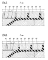
- Fig. 7,8 und 9 zeigen unterschiedliche Ring - Erhebungen 63',63",63"', denen angepaßte Form - förderrillen in der Halbkokille 2a entsprechen. In Fig. 7 ist eine Ring - Erhebung 63' mit einer radial abfallenden Förderfläche 68' ausgebildet, der eine entsprechende Förderfläche als Begrenzung der zugeordneten Rippen - Formausnehmung ent - spricht. Diese Förderfläche 68' verläuft also etwa senkrecht zur in den Fig. 7,8 und 9 nicht dargestellten Mittel - Längs Achse 41. Gleiches gilt für die Förderflächen 68" und 68'" bei den Ausgestal - tungen nach den Fig. 8 und 9. Bei Fig. 7 ist der Übergang zur flach abfallenden Flanke 69' mit einer deutlichen Abrundung 70 versehen. Durch diese Abrundung 70 entsteht in der entsprechenden Förderrille der Halbkokille 2a keine Kerbwirkung. Die Flanke 69' wird an der Begrenzungsfläche 65 der Halbkokille ausgeformt.
- Bei den Ausgestaltungen nach Fig. 8 und 9 ist der Übergang von der Förderfläche 68" bzw. 68'" zur Flanke 69" bzw. 69"' spitz ausgebildet. Dies führt zu einer entsprechend guten Förderwirkung, allerdings zu einer nachteiligen Kerbwirkung in der Halbkokille 2a. Bei der Ausgestaltung nach Fig. 9 sind die Ring - Erhebungen 63'" mit geringerer radialer Höhe und in geringerem Abstand voneinan - der ausgebildet.
- Die Rippen 24 weisen eine radiale Höhe h - gemessen vom Fuß der Förderflächen 68 bzw. Flanken 69 an - auf, die etwa 0,035 i ist, wobei i den Innendurchmesser des Rohres 23 bezeichnet. Die minimale Rohrwanddicke b entspricht etwa 0,015 i. Die Höhe der Ring - Erhebungen 63 beträgt etwa 0,12 b bis 0,16 b.
Claims (8)
Applications Claiming Priority (2)
| Application Number | Priority Date | Filing Date | Title |
|---|---|---|---|
| DE3725286 | 1987-07-30 | ||
| DE19873725286 DE3725286A1 (de) | 1987-07-30 | 1987-07-30 | Verfahren und vorrichtung zum herstellen eines rippen-rohres aus kunststoff |
Publications (4)
| Publication Number | Publication Date |
|---|---|
| EP0301189A2 EP0301189A2 (de) | 1989-02-01 |
| EP0301189A3 EP0301189A3 (en) | 1990-09-05 |
| EP0301189B1 true EP0301189B1 (de) | 1993-05-12 |
| EP0301189B2 EP0301189B2 (de) | 1998-08-26 |
Family
ID=6332723
Family Applications (1)
| Application Number | Title | Priority Date | Filing Date |
|---|---|---|---|
| EP88108096A Expired - Lifetime EP0301189B2 (de) | 1987-07-30 | 1988-05-20 | Verfahren und Vorrichtung zum Herstellen eines Rippen-Rohres aus Kunststoff |
Country Status (10)
| Country | Link |
|---|---|
| US (1) | US4900503A (de) |
| EP (1) | EP0301189B2 (de) |
| JP (1) | JPH0624736B2 (de) |
| CN (1) | CN1012721B (de) |
| BR (1) | BR8803766A (de) |
| CA (1) | CA1314678C (de) |
| DE (2) | DE3725286A1 (de) |
| ES (1) | ES2040288T3 (de) |
| FI (1) | FI883531A7 (de) |
| SU (1) | SU1648244A3 (de) |
Cited By (1)
| Publication number | Priority date | Publication date | Assignee | Title |
|---|---|---|---|---|
| DE102009035040A1 (de) | 2009-07-28 | 2011-02-03 | Hegler, Ralph Peter, Dr.-Ing. | Verfahren zur fortlaufenden Herstellung eines Rohres und Vorrichtung zur Durchführung des Verfahrens |
Families Citing this family (37)
| Publication number | Priority date | Publication date | Assignee | Title |
|---|---|---|---|---|
| CA1303315C (en) * | 1988-09-16 | 1992-06-16 | Manfred A.A. Lupke | Apparatus for producing pipe with annular ribs |
| CA1298450C (en) * | 1988-09-16 | 1992-04-07 | Manfred A. A. Lupke | Suction applying molded blocks in pipe forming apparatus |
| DE3921075A1 (de) * | 1989-06-28 | 1991-01-03 | Wilhelm Hegler | Kunststoff-rohr zur kanalrohrsanierung |
| FI85239C (fi) * | 1989-07-12 | 1992-03-25 | Uponor Nv | Anordning foer framstaellning av kamflaensroer. |
| EP0453647B1 (de) * | 1990-04-27 | 1994-02-23 | REHAU AG + Co | Verfahren zur Herstellung von Profilen |
| DE4111228A1 (de) * | 1991-04-08 | 1992-10-15 | Wilhelm Hegler | Vorrichtung zur herstellung von kunststoff-rohren |
| DE4111229A1 (de) * | 1991-04-08 | 1992-10-15 | Wilhelm Hegler | Vorrichtung zur herstellung von kunststoff-rohren |
| US5141697A (en) * | 1991-04-29 | 1992-08-25 | Miner Enterprises, Inc. | Method of making a segmented polymer energy absorption device |
| WO1992022416A1 (en) * | 1991-06-14 | 1992-12-23 | Lupke Manfred Arno Alfred | Travelling mold tunnel apparatus for smooth walled pipe |
| DE4129855C2 (de) * | 1991-09-07 | 1999-09-16 | Wilhelm Hegler | Verfahren zum Verschweißen von aus thermoplastischem Kunststoff bestehenden Rohren |
| GB9212684D0 (en) * | 1992-06-15 | 1992-07-29 | Lupke Manfred Arno Alfred | A method and apparatus for forming profiled tubes |
| DE4224514A1 (de) * | 1992-07-24 | 1994-01-27 | Wilhelm Hegler | Vorrichtung zum Herstellen eines Kunststoff-Rohres mit Querprofilierung |
| JP2744743B2 (ja) * | 1992-12-28 | 1998-04-28 | 日本金銭機械株式会社 | 紙葉類鑑別装置 |
| US5545369A (en) * | 1993-09-08 | 1996-08-13 | Corma, Inc. | Clamshell corrugators and the like |
| DE4414977A1 (de) * | 1994-04-29 | 1995-11-02 | Wilhelm Hegler | Vorrichtung zur Herstellung von Rohren aus thermoplastischem Kunststoff mit Querprofilierung |
| DE19504501A1 (de) * | 1995-02-13 | 1996-08-14 | Wilhelm Hegler | Verfahren und Anlage zur Herstellung eines Mehrschicht-Rohres aus thermoplastischem Kunststoff, insbesondere Polyolefin |
| US5707088A (en) * | 1995-08-28 | 1998-01-13 | Contech Construction Products, Inc. | Joint for coupling plastic corrugated pipes |
| DE19535231A1 (de) * | 1995-09-22 | 1997-03-27 | Hegler Ralph Peter | Vorrichtung zur Herstellung von Rohren aus thermoplastischem Kunststoff mit Querprofilierung |
| US5851476A (en) * | 1996-05-17 | 1998-12-22 | Miner Enterprises, Inc. | Method of manufacturing a bellowed seal |
| US5824351A (en) * | 1996-07-05 | 1998-10-20 | Lupke; Manfred A. A. | Molding apparatus with non-reflective mold tunnels |
| DE29809587U1 (de) * | 1997-03-12 | 1998-11-26 | Lupke, Manfred Arno Alfred, Concord, Ontario | Vorrichtung zum Formen von Kunststoffteilen |
| US7104574B2 (en) | 2000-01-20 | 2006-09-12 | Uponor Eti Company | Corrugated pipe connection joint |
| US6877976B2 (en) * | 2002-09-09 | 2005-04-12 | Manfred A. A. Lupke | Molding die for ribbed pipe |
| US8733405B2 (en) * | 2005-03-14 | 2014-05-27 | Advanced Drainage Systems, Inc. | Corrugated pipe with outer layer |
| US7484535B2 (en) * | 2005-03-14 | 2009-02-03 | Advanced Drainage Systems, Inc. | Corrugated pipe with outer layer |
| AU2006316231B2 (en) * | 2005-11-16 | 2012-07-12 | Manufacturing Systems Limited | Improvements in or relating to forming apparatus |
| CA2622695C (en) * | 2007-02-26 | 2015-11-03 | Advanced Drainage Systems, Inc. | Pipe extrusion die flow path apparatus and method |
| CA2622692C (en) * | 2007-02-26 | 2015-10-06 | Advanced Drainage Systems, Inc. | Defined ratio dual-wall pipe die |
| US20080290538A1 (en) * | 2007-05-23 | 2008-11-27 | Biesenberger Jeffrey J | Extruder ramp-up control system and method |
| US8820800B2 (en) * | 2007-11-16 | 2014-09-02 | Advanced Drainage Systems, Inc. | Multi-wall corrugated pipe couplings and methods |
| US8820801B2 (en) * | 2007-11-16 | 2014-09-02 | Advanced Drainage System, Inc. | Multi-wall corrugated pipe couplings and methods |
| US8114324B2 (en) * | 2008-10-14 | 2012-02-14 | Advanced Drainage Systems, Inc. | Apparatus and method for pressing an outer wall of pipe |
| US7988438B2 (en) * | 2008-02-11 | 2011-08-02 | Advanced Drainage Systems, Inc. | Extrusion die vacuum seals |
| US8550807B2 (en) * | 2008-05-28 | 2013-10-08 | Advanced Drainage Systems, Inc. | In-mold punch apparatus and methods |
| US8360140B2 (en) * | 2010-03-16 | 2013-01-29 | Miner Elastomer Products Corporation | Well head lubricator assembly |
| CA2865601C (en) * | 2014-09-30 | 2022-04-26 | Manfred A. A. Lupke | Mold block return |
| CN118927493B (zh) * | 2024-07-23 | 2025-02-21 | 徐州众泽机械科技有限公司 | 一种塑料波纹管成型的气动脱模装置 |
Family Cites Families (15)
| Publication number | Priority date | Publication date | Assignee | Title |
|---|---|---|---|---|
| FR1413172A (fr) * | 1959-02-21 | 1965-10-08 | Fraenk Isolierrohr & Metall | Dispositif de fabrication de tuyaux en matière synthétique à parois à ondulations transversales |
| NL124750C (de) * | 1959-02-21 | 1900-01-01 | ||
| DE2061027C3 (de) * | 1970-12-11 | 1982-03-04 | Wilhelm 8730 Bad Kissingen Hegler | Vorrichtung zum Anbringen einer Querprofilierung an einem Rohr aus thermoplastischem Kunststoff |
| US3891007A (en) * | 1972-07-03 | 1975-06-24 | Dayco Corp | Exteriorly corrugated hose of composite materials |
| SE381001B (sv) * | 1973-10-22 | 1975-11-24 | Erik G W Nordstroem | Forfarande och anordning for framstellning av kamflensror av plast |
| DE2362444C2 (de) * | 1973-12-15 | 1983-06-01 | Reifenhäuser KG, 5210 Troisdorf | Vorrichtung zum Herstellen eines Rohres aus thermoplastischem Kunststoff mit Außenrippen und glattem Innenkanal |
| US4319872A (en) * | 1976-12-01 | 1982-03-16 | Lupke Gerd Paul Heinrich | Apparatus for producing thermoplastic tubing |
| FR2424123A1 (fr) * | 1978-04-24 | 1979-11-23 | Armosig | Procede et appareillage pour la fabrication en continu de profiles tubulaires ailetes en matiere synthetique |
| DE2832350A1 (de) * | 1978-07-22 | 1980-01-31 | Wilhelm Hegler | Vorrichtung zur herstellung von rohren aus thermoplastischem kunststoff mit querprofilierung |
| JPS5835453B2 (ja) * | 1980-03-19 | 1983-08-02 | 三井東圧グリ−ン施設株式会社 | 偏肉管の製造方法 |
| DE3120480A1 (de) * | 1981-05-22 | 1982-12-09 | Hegler, Wilhelm, 8730 Bad Kissingen | Vorrichtung zur herstellung von kunststoffrohren mit querrillen |
| SE449456B (sv) * | 1983-11-15 | 1987-05-04 | Uponor Ab | Forfarande och anordning for framstellning av ror varvid formbacksdelarna er delade i formstreckans lengsriktning |
| DE3513708C2 (de) * | 1985-04-12 | 1994-04-21 | Drossbach Gmbh & Co Kg | Extrusionskopf zur Herstellung doppelwandiger Kunststoffrohre mit zylindrischem Innenrohr und quergewelltem Außenrohr |
| FI74654C (fi) * | 1986-01-13 | 1988-03-10 | Uponor Nv | Anordning och foerfarande foer framstaellning av kamflaensroer. |
| FI77405C (fi) * | 1986-03-20 | 1989-03-10 | Uponor Nv | Foerfarande och anordning foer framstaellning av kamflaensroer. |
-
1987
- 1987-07-30 DE DE19873725286 patent/DE3725286A1/de not_active Ceased
-
1988
- 1988-05-20 EP EP88108096A patent/EP0301189B2/de not_active Expired - Lifetime
- 1988-05-20 ES ES198888108096T patent/ES2040288T3/es not_active Expired - Lifetime
- 1988-05-20 DE DE8888108096T patent/DE3880909D1/de not_active Expired - Fee Related
- 1988-06-22 CA CA000570089A patent/CA1314678C/en not_active Expired - Fee Related
- 1988-07-11 SU SU884356042A patent/SU1648244A3/ru active
- 1988-07-25 JP JP63183734A patent/JPH0624736B2/ja not_active Expired - Lifetime
- 1988-07-27 FI FI883531A patent/FI883531A7/fi not_active Application Discontinuation
- 1988-07-29 BR BR8803766A patent/BR8803766A/pt not_active Application Discontinuation
- 1988-07-29 CN CN88104682A patent/CN1012721B/zh not_active Expired
- 1988-07-29 US US07/227,424 patent/US4900503A/en not_active Expired - Fee Related
Cited By (1)
| Publication number | Priority date | Publication date | Assignee | Title |
|---|---|---|---|---|
| DE102009035040A1 (de) | 2009-07-28 | 2011-02-03 | Hegler, Ralph Peter, Dr.-Ing. | Verfahren zur fortlaufenden Herstellung eines Rohres und Vorrichtung zur Durchführung des Verfahrens |
Also Published As
| Publication number | Publication date |
|---|---|
| EP0301189A2 (de) | 1989-02-01 |
| CA1314678C (en) | 1993-03-23 |
| FI883531A0 (fi) | 1988-07-27 |
| US4900503A (en) | 1990-02-13 |
| CN1031047A (zh) | 1989-02-15 |
| BR8803766A (pt) | 1989-02-21 |
| CN1012721B (zh) | 1991-06-05 |
| DE3880909D1 (de) | 1993-06-17 |
| EP0301189A3 (en) | 1990-09-05 |
| EP0301189B2 (de) | 1998-08-26 |
| DE3725286A1 (de) | 1989-02-09 |
| ES2040288T3 (es) | 1993-10-16 |
| JPS6442210A (en) | 1989-02-14 |
| FI883531A7 (fi) | 1989-01-31 |
| SU1648244A3 (ru) | 1991-05-07 |
| JPH0624736B2 (ja) | 1994-04-06 |
Similar Documents
| Publication | Publication Date | Title |
|---|---|---|
| EP0301189B2 (de) | Verfahren und Vorrichtung zum Herstellen eines Rippen-Rohres aus Kunststoff | |
| EP0065729B1 (de) | Vorrichtung zur Herstellung von Kunststoffrohren mit Querrillen | |
| EP0563575B1 (de) | Verfahren und Vorrichtung zur fortlaufenden Herstellung eines Verbundrohres mit Rohr-Muffe | |
| EP0600214B1 (de) | Verfahren und Vorrichtung zur fortlaufenden Herstellung eines Verbundrohres mit einem aussen im wesentlichen glatten Abschnitt | |
| EP0315012B1 (de) | Verfahren zum Herstellen eines innen glatten, aussen gerippten Rohres aus extrudierbarem Kunststoff sowie Vorrichtung zur Durchführung des Verfahrens | |
| WO1991018732A1 (de) | Speicherkopf für eine blasformmaschine | |
| DE3632225A1 (de) | Verfahren und vorrichtung zur herstellung von rippenflanschrohren | |
| DE3247333A1 (de) | Vorrichtung zum kalibrieren eines rohres aus kunststoff durch strangpressen | |
| EP0834386B1 (de) | Vorrichtung zur Herstellung von Kunststoff-Verbund-Rohren | |
| EP1254014B1 (de) | Vorrichtung zur herstellung von profilierten kunststoff-rohren | |
| DE69018964T2 (de) | Verfahren und vorrichtung zur herstellung von gerippten rohren. | |
| EP0464411B1 (de) | Vorrichtung zur Herstellung von Kunststoff-Rohren | |
| EP2065159A1 (de) | Vorrichtung zur fortlaufenden Herstellung eines Verbundrohres mit Rohrmuffe | |
| DE10152638A1 (de) | Vorrichtung zur Herstellung von gewellten Kunststoff-Rohren | |
| DE2009914B2 (de) | Folienblaskopf zur herstellung von kunststoff-schlauchfolien | |
| DE2911833C3 (de) | Gerader Spritzkopf zum Extrudieren zweier zueinander konzentrischer Kunststoffrohre | |
| EP4434716A1 (de) | Kunststoffrohr und vorrichtung zur kontinuierlichen herstellung eines rohrgrundkörpers für ein derartiges kunststoffrohr | |
| EP0417236A1 (de) | Düsenwerkzeug zum formen zähflüssiger massen | |
| DE69601509T2 (de) | Vakuumzuführkreislauf für eine Anlage zum Herstellen von Wellenrohren | |
| DE3815298C2 (de) | ||
| EP3153296B1 (de) | Spritzkopf für eine vorrichtung zur herstellung eines verbundrohres | |
| DE3013020A1 (de) | Kuehl- und kalibriervorrichtung fuer stranggepresste kunststoffprofile | |
| DE2404123A1 (de) | Verfahren und vorrichtung zur herstellung von kunststoffrohren mit einer innenrippe | |
| AT301847B (de) | Verfahren und Vorrichtung zur Herstellung von Leisten durch Aufbringen eines nahtlosen Kunststoffüberzuges auf eine Kernleiste | |
| DE3827772A1 (de) | Vorrichtung und verfahren zur formgebung von halbzeug aus hochmolekularen kunststoffen |
Legal Events
| Date | Code | Title | Description |
|---|---|---|---|
| PUAI | Public reference made under article 153(3) epc to a published international application that has entered the european phase |
Free format text: ORIGINAL CODE: 0009012 |
|
| AK | Designated contracting states |
Kind code of ref document: A2 Designated state(s): DE ES FR GB IT NL SE |
|
| PUAL | Search report despatched |
Free format text: ORIGINAL CODE: 0009013 |
|
| AK | Designated contracting states |
Kind code of ref document: A3 Designated state(s): DE ES FR GB IT NL SE |
|
| 17P | Request for examination filed |
Effective date: 19901211 |
|
| 17Q | First examination report despatched |
Effective date: 19920107 |
|
| GRAA | (expected) grant |
Free format text: ORIGINAL CODE: 0009210 |
|
| AK | Designated contracting states |
Kind code of ref document: B1 Designated state(s): DE ES FR GB IT NL SE |
|
| PGFP | Annual fee paid to national office [announced via postgrant information from national office to epo] |
Ref country code: ES Payment date: 19930519 Year of fee payment: 6 |
|
| ET | Fr: translation filed | ||
| ITF | It: translation for a ep patent filed | ||
| REF | Corresponds to: |
Ref document number: 3880909 Country of ref document: DE Date of ref document: 19930617 |
|
| GBT | Gb: translation of ep patent filed (gb section 77(6)(a)/1977) |
Effective date: 19930525 |
|
| REG | Reference to a national code |
Ref country code: ES Ref legal event code: FG2A Ref document number: 2040288 Country of ref document: ES Kind code of ref document: T3 |
|
| PLBI | Opposition filed |
Free format text: ORIGINAL CODE: 0009260 |
|
| 26 | Opposition filed |
Opponent name: OY UPONOR AB Effective date: 19940212 |
|
| PG25 | Lapsed in a contracting state [announced via postgrant information from national office to epo] |
Ref country code: ES Free format text: LAPSE BECAUSE OF NON-PAYMENT OF DUE FEES Effective date: 19940521 |
|
| NLR1 | Nl: opposition has been filed with the epo |
Opponent name: OY UPONOR AB |
|
| EAL | Se: european patent in force in sweden |
Ref document number: 88108096.4 |
|
| PGFP | Annual fee paid to national office [announced via postgrant information from national office to epo] |
Ref country code: SE Payment date: 19950523 Year of fee payment: 8 |
|
| PGFP | Annual fee paid to national office [announced via postgrant information from national office to epo] |
Ref country code: NL Payment date: 19950531 Year of fee payment: 8 |
|
| PG25 | Lapsed in a contracting state [announced via postgrant information from national office to epo] |
Ref country code: SE Effective date: 19960521 |
|
| PG25 | Lapsed in a contracting state [announced via postgrant information from national office to epo] |
Ref country code: NL Effective date: 19961201 |
|
| EUG | Se: european patent has lapsed |
Ref document number: 88108096.4 |
|
| NLV4 | Nl: lapsed or anulled due to non-payment of the annual fee |
Effective date: 19961201 |
|
| PGFP | Annual fee paid to national office [announced via postgrant information from national office to epo] |
Ref country code: GB Payment date: 19970502 Year of fee payment: 10 |
|
| APAC | Appeal dossier modified |
Free format text: ORIGINAL CODE: EPIDOS NOAPO |
|
| PLAW | Interlocutory decision in opposition |
Free format text: ORIGINAL CODE: EPIDOS IDOP |
|
| PG25 | Lapsed in a contracting state [announced via postgrant information from national office to epo] |
Ref country code: GB Free format text: LAPSE BECAUSE OF NON-PAYMENT OF DUE FEES Effective date: 19980520 |
|
| PUAH | Patent maintained in amended form |
Free format text: ORIGINAL CODE: 0009272 |
|
| STAA | Information on the status of an ep patent application or granted ep patent |
Free format text: STATUS: PATENT MAINTAINED AS AMENDED |
|
| 27A | Patent maintained in amended form |
Effective date: 19980826 |
|
| AK | Designated contracting states |
Kind code of ref document: B2 Designated state(s): DE ES FR GB IT NL SE |
|
| ET3 | Fr: translation filed ** decision concerning opposition | ||
| GBPC | Gb: european patent ceased through non-payment of renewal fee |
Effective date: 19980520 |
|
| REG | Reference to a national code |
Ref country code: ES Ref legal event code: FD2A Effective date: 19990405 |
|
| PGFP | Annual fee paid to national office [announced via postgrant information from national office to epo] |
Ref country code: FR Payment date: 20010518 Year of fee payment: 14 |
|
| PGFP | Annual fee paid to national office [announced via postgrant information from national office to epo] |
Ref country code: DE Payment date: 20010719 Year of fee payment: 14 |
|
| PG25 | Lapsed in a contracting state [announced via postgrant information from national office to epo] |
Ref country code: DE Free format text: LAPSE BECAUSE OF NON-PAYMENT OF DUE FEES Effective date: 20021203 |
|
| PG25 | Lapsed in a contracting state [announced via postgrant information from national office to epo] |
Ref country code: FR Free format text: LAPSE BECAUSE OF NON-PAYMENT OF DUE FEES Effective date: 20030131 |
|
| REG | Reference to a national code |
Ref country code: FR Ref legal event code: ST |
|
| PG25 | Lapsed in a contracting state [announced via postgrant information from national office to epo] |
Ref country code: IT Free format text: LAPSE BECAUSE OF NON-PAYMENT OF DUE FEES;WARNING: LAPSES OF ITALIAN PATENTS WITH EFFECTIVE DATE BEFORE 2007 MAY HAVE OCCURRED AT ANY TIME BEFORE 2007. THE CORRECT EFFECTIVE DATE MAY BE DIFFERENT FROM THE ONE RECORDED. Effective date: 20050520 |
|
| APAH | Appeal reference modified |
Free format text: ORIGINAL CODE: EPIDOSCREFNO |