EP0301606B1 - Belüftungsanlage für Flugzeugkabinen - Google Patents
Belüftungsanlage für Flugzeugkabinen Download PDFInfo
- Publication number
- EP0301606B1 EP0301606B1 EP88200157A EP88200157A EP0301606B1 EP 0301606 B1 EP0301606 B1 EP 0301606B1 EP 88200157 A EP88200157 A EP 88200157A EP 88200157 A EP88200157 A EP 88200157A EP 0301606 B1 EP0301606 B1 EP 0301606B1
- Authority
- EP
- European Patent Office
- Prior art keywords
- air
- cabin
- ventilation
- disposed
- aircraft
- Prior art date
- Legal status (The legal status is an assumption and is not a legal conclusion. Google has not performed a legal analysis and makes no representation as to the accuracy of the status listed.)
- Expired - Lifetime
Links
- 238000009423 ventilation Methods 0.000 title claims description 61
- 238000004891 communication Methods 0.000 claims description 18
- 239000012530 fluid Substances 0.000 claims description 18
- 239000000356 contaminant Substances 0.000 claims description 17
- 239000000779 smoke Substances 0.000 claims description 17
- 238000013022 venting Methods 0.000 claims description 11
- 238000000034 method Methods 0.000 claims description 10
- 230000002503 metabolic effect Effects 0.000 claims description 9
- 230000003134 recirculating effect Effects 0.000 claims description 7
- CURLTUGMZLYLDI-UHFFFAOYSA-N Carbon dioxide Chemical compound O=C=O CURLTUGMZLYLDI-UHFFFAOYSA-N 0.000 claims description 6
- 238000010408 sweeping Methods 0.000 claims description 6
- 229910002092 carbon dioxide Inorganic materials 0.000 claims description 3
- 239000001569 carbon dioxide Substances 0.000 claims description 3
- 235000019504 cigarettes Nutrition 0.000 claims description 2
- 238000009792 diffusion process Methods 0.000 description 3
- 230000008901 benefit Effects 0.000 description 2
- 238000011109 contamination Methods 0.000 description 2
- 230000000694 effects Effects 0.000 description 2
- 239000003344 environmental pollutant Substances 0.000 description 2
- 238000012423 maintenance Methods 0.000 description 2
- 231100000719 pollutant Toxicity 0.000 description 2
- 239000006227 byproduct Substances 0.000 description 1
- 230000000711 cancerogenic effect Effects 0.000 description 1
- 231100000315 carcinogenic Toxicity 0.000 description 1
- 230000001143 conditioned effect Effects 0.000 description 1
- 230000003750 conditioning effect Effects 0.000 description 1
- 238000005265 energy consumption Methods 0.000 description 1
- 239000000203 mixture Substances 0.000 description 1
- 238000012986 modification Methods 0.000 description 1
- 230000004048 modification Effects 0.000 description 1
- 238000007789 sealing Methods 0.000 description 1
- 230000000391 smoking effect Effects 0.000 description 1
Images

Classifications
-
- B—PERFORMING OPERATIONS; TRANSPORTING
- B64—AIRCRAFT; AVIATION; COSMONAUTICS
- B64D—EQUIPMENT FOR FITTING IN OR TO AIRCRAFT; FLIGHT SUITS; PARACHUTES; ARRANGEMENT OR MOUNTING OF POWER PLANTS OR PROPULSION TRANSMISSIONS IN AIRCRAFT
- B64D13/00—Arrangements or adaptations of air-treatment apparatus for aircraft crew or passengers, or freight space
-
- B—PERFORMING OPERATIONS; TRANSPORTING
- B64—AIRCRAFT; AVIATION; COSMONAUTICS
- B64D—EQUIPMENT FOR FITTING IN OR TO AIRCRAFT; FLIGHT SUITS; PARACHUTES; ARRANGEMENT OR MOUNTING OF POWER PLANTS OR PROPULSION TRANSMISSIONS IN AIRCRAFT
- B64D13/00—Arrangements or adaptations of air-treatment apparatus for aircraft crew or passengers, or freight space
- B64D2013/003—Cabin ventilation nozzles
-
- B—PERFORMING OPERATIONS; TRANSPORTING
- B64—AIRCRAFT; AVIATION; COSMONAUTICS
- B64D—EQUIPMENT FOR FITTING IN OR TO AIRCRAFT; FLIGHT SUITS; PARACHUTES; ARRANGEMENT OR MOUNTING OF POWER PLANTS OR PROPULSION TRANSMISSIONS IN AIRCRAFT
- B64D13/00—Arrangements or adaptations of air-treatment apparatus for aircraft crew or passengers, or freight space
- B64D13/06—Arrangements or adaptations of air-treatment apparatus for aircraft crew or passengers, or freight space the air being conditioned
- B64D2013/0603—Environmental Control Systems
- B64D2013/0625—Environmental Control Systems comprising means for distribution effusion of conditioned air in the cabin
-
- B—PERFORMING OPERATIONS; TRANSPORTING
- B64—AIRCRAFT; AVIATION; COSMONAUTICS
- B64D—EQUIPMENT FOR FITTING IN OR TO AIRCRAFT; FLIGHT SUITS; PARACHUTES; ARRANGEMENT OR MOUNTING OF POWER PLANTS OR PROPULSION TRANSMISSIONS IN AIRCRAFT
- B64D13/00—Arrangements or adaptations of air-treatment apparatus for aircraft crew or passengers, or freight space
- B64D13/06—Arrangements or adaptations of air-treatment apparatus for aircraft crew or passengers, or freight space the air being conditioned
- B64D2013/0603—Environmental Control Systems
- B64D2013/0688—Environmental Control Systems with means for recirculating cabin air
-
- Y—GENERAL TAGGING OF NEW TECHNOLOGICAL DEVELOPMENTS; GENERAL TAGGING OF CROSS-SECTIONAL TECHNOLOGIES SPANNING OVER SEVERAL SECTIONS OF THE IPC; TECHNICAL SUBJECTS COVERED BY FORMER USPC CROSS-REFERENCE ART COLLECTIONS [XRACs] AND DIGESTS
- Y02—TECHNOLOGIES OR APPLICATIONS FOR MITIGATION OR ADAPTATION AGAINST CLIMATE CHANGE
- Y02T—CLIMATE CHANGE MITIGATION TECHNOLOGIES RELATED TO TRANSPORTATION
- Y02T50/00—Aeronautics or air transport
- Y02T50/50—On board measures aiming to increase energy efficiency
Definitions
- This invention relates to a ventilation system for an aircraft cabin as described in the preamble of claim 1 and 9, and to a method of ventilating an aircraft cabin as described in the preamble of claim 17.
- Such ventilation system and method are generally kwown in the aircraft industry.
- An aircraft cabin comprises a sealed, pressurized chamber. As air is vented overboard both intentionally and from small leaks at doors and at other points, fresh air is compressed, temperature conditioned and mixed with recirculated air as necessary for proper ventilation and maintenance of cabin pressure. In prior aircraft ventilation systems, air is drawn from various points within the cabin and recirculated as if the cabin comprised but a single uniformly contaminated zone. Because the source of smoke and most other exhalant contaminants in an aircraft cabin is the passengers who are seated in the cabin, and because the concentration of these contaminants is much greater at and above the heads of the passengers, viewing the aircraft cabin as a single zone is inaccurate.
- a ventilation sytem comprising means for supplying a ventilation airflow through one or more openings disposed generally above a passenger seating area in the cabin and for distributing that airflow both downwardly and laterally within the cabin, means for drawing air from the cabin at a location where the air is heavily contaminated with smoke and passenger metabolic exhalants, and means for drawing from an area proximate the floor of the cabin, air that is relatively free of contaminants.
- this document neither discloses nor suggests venting the heavily contaminated air outside the cabin and recirculating only the relatively contaminant free air back into the cabin.
- the present invention is directed to solving the above problem and provides a ventilation system for reducing the concentration of gaseous and particular contaminants in an aircraft cabin that is divided into an upper zone disposed below an overhead shelf and a lower zone disposed adjacent a cabin floor; air in the upper zone having a relatively greater concentration of the contaminants than has air in the lower zone, the ventilation system comprising: means disposed adjacent the upper zone for drawing air from the upper zone, means disposed adjacent the lower zone for drawing air from the lower zone, means for venting at least a portion of the air drawn from the cabin outside the aircraft, and discharge means for directing at least a portion of the air drawn from the cabin back into the cabin, characterized in that: the means for drawing air from the upper zone is disposed below the overhead shelf and is in fluid communication with the venting means, and the discharge means is in fluid communication with the means for drawing air from the lower zone and with a source of pressurized fresh air, the air from the lower zone and the fresh air being mixed, and directs the mixed air into the cabin from a location disposed above the upper zone creating
- a ventilation system for an aircraft cabin having a storage bin disposed overhead a passenger seating area comprising:
- the present invention further provides, in an aircraft cabin, a method for removing air contaminated by smoke and passenger metabolic exhalants while maintaining an airflow in the cabin that is stable and symmetrical about a vertical centre plane extending longitudinally through the cabin comprising the steps of:
- the resulting airflow through the cabin sweeps the contaminated air from the upper zone into the exhaust duct with little or no mixing between the supply air and the contaminated air, provides an adequate air supply to the passengers in the cabin as required for ventilation and to maintain cabin pressure, and can be adjusted to accomplish the preceding without creating an airflow velocity that would cause the passengers to feel discomfort due to drafts.
- the present invention prevents carbon dioxide build-up in the cabin, and provides a degree of cabin ventilation that in prior art systems could only be achieved by introducing a large volume of fresh pressurized air, with concomitant excessive energy consumption.
- supply air is discharged into the cabin from a discharge duct located in the center of the ceiling, and from discharge ducts disposed adjacent an inwardly extending edge of the overhead shelf.
- the present ventilation system includes a discharge nozzle disposed above the overhead shelf and oriented to direct the supply air into the cabin downwardly over a surface of the shelf.
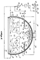
- FIGURE 1 is a partially cut-away, cross-sectional view of an aircraft fuselage showing a cabin to which a first embodiment of the present invention is applied, and schematically representing the supply, exhaust and return airflow paths.
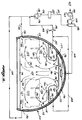
- FIGURE 2 is a partially cut-away, cross-sectional view of an aircraft fuselage equipped with a second embodiment of the present invention, showing the supply, return and exhaust airflow paths in a schematic fashion.
- FIGURE 3 schematically illustrates the direction of airflow in one-half of the cabin for the first embodiment, wherein the supply air velocity from a center discharge port is too high.
- FIGURE 4 illustrates an airflow pattern in the cabin for the first embodiment of the present invention, wherein the supply airflow from a discharge nozzle disposed below an overhead shelf has an excessive velocity.
- FIGURE 5 illustrates schematically the airflow pattern in the cabin for the first embodiment wherein the supply air discharged from a center discharge port is not properly diffused.
- FIGURE 6 shows an acceptable cabin airflow pattern for the first embodiment.
- a first embodiment of the present invention is shown installed in an aircraft fuselage generally represented by reference numeral 10.
- a cabin 12 of the aircraft includes curved sidewalls 14 on each side, joined by a floor 16.
- the area of the aircraft below the floor is not shown since it is not particularly important with regard to airflow within cabin 12.
- the top portion of cabin 12 is defined by a ceiling panel 18.
- a ceiling panel 18 Located below ceiling panel 18 are disposed storage bins 20, which extend into cabin 12 from each sidewall 14. Storage bins 20 are thus disposed immediately above seating areas 22 at opposite sides of a center aisle 24.
- the space immediately above seating area 22 and below storage bin 20 comprises an upper zone 26 in which smoke and other exhalant contaminants produced by passengers seated within seating areas 22 is likely to be concentrated.
- An object of the present invention is to provide a ventilation system which is capable of sweeping the contaminated air from the upper zone 26, preventing it from mixing with the rest of the air in cabin 12 and with the supply air that is recirculated back through the ventilation system.
- a lower zone 27 in cabin 12 is generally defined by floor 16 and the lower portion of seating areas 22. Air is drawn from the lower zone through floor return air ducts 30 at each side of the cabin. As viewed in FIGURE 1, air exiting cabin 12 through the left return air duct 30 passes through a return air line 32 and mixes with air exiting through the return air duct 30 disposed on the opposite sidewall 14, which flows through return air line 34. The return airflow from return air ducts 30 is drawn into a suction port 36 of a return air fan 38 from which it is discharged for resupply to the cabin as will presently be described.
- exhaust ducts 40 which are disposed at each side of the cabin, immediately below the point where overhead storage bins 20 adjoin sidewalls 14.
- air drawn from the left exhaust duct 40 passes through exhaust air line 42 and combines with air drawn from the exhaust duct 40 disposed on the opposite sidewall 14, after passing through exhaust air line 44.
- a portion of the air drawn from the cabin through exhaust ducts 40 may be recirculated into suction port 36 of recirculating fan 38.
- a substantial portion of the air passing through exhaust ducts 40 is vented overboard through a three-way valve 46, into the outdoor ambient 50. To the extent that contaminated air in first zone 26 is vented overboard, the smoke and other exhalants contained within that air are not recirculated into the ventilation air supplied to cabin 12.
- air pack 62 comprises a compressor and temperature conditioning system as will be well known to those of ordinary skill in the aircraft ventilation systems art.
- Air pack 62 draws fresh air from the outdoor ambient 64 into a suction port 66, compresses it, temperature conditions the air, and provides it to mixing box 56 through supply air line 58, where it is mixed with the filtered return air provided through return air line 52.
- the mixed fresh and return air passes from mixing box 56 through a supply air line 68 which splits into separate supply air lines 70 and 72 to provide supply air to supply air plenums 74 disposed above ceiling 18.
- Supply air from supply air plenums 74 travels downwardly through passages 76 which extend below the interior portion of overhead storage bins 20 to discharge nozzles 78 which are disposed below the inwardly extending ends of the storage bins.
- Supply air exiting discharge nozzles 78 is directed as shown by arrows 80 laterally across the upper portion of upper zone 26 toward the sidewalls 14 and, more specifically, toward exhaust ducts 40.
- the flow of air from discharge nozzles 78 thus tends to sweep across the upper portion of the upper zone 26, entraining air that is contaminated with smoke and other exhalant pollutants, and moving that air toward the exhaust ducts 40.
- Supply air is also conveyed from supply air plenums 74 through supply air lines 82 to a supply air duct 84 disposed in the center of ceiling 18, immediately above aisle 24.
- supply air duct 84 is covered by a diffuser panel 86 that breaks up directional airflow from a discharge nozzle (not shown in detail) comprising a lower portion of supply air duct 84.
- Diffuser panel 86 tends to diffuse the airflow pattern without unduly reducing the volumetric flow of air into cabin 12 from supply air duct 84, and may comprise a plurality of relatively small orifices, a screen or other similar diffusion panel. Alternatively, a diffusion nozzle could be incorporated into supply air duct 84.
- the supply airflow thus tends to sweep through the seating area 22, carrying contaminated air in upper zone 26 toward exhaust ducts 40.
- Adjacent floor 16 the supply airflow follows a flow path as generally indicated by arrows 92 and sweeps through the lower zone 27 adjacent floor 16, following a flow path as generally indicated by arrows 92, toward return air ducts 30.
- FIGURES 3-6 The importance of the airflow patterns represented by arrows 90 and 92 and the manner in which the airflow pattern is affected by the relative velocities and directionality of air entering cabin 12 from supply air ducts 84 and from nozzles 78 is illustrated in FIGURES 3-6 and discussed below.
- FIGURE 2 A second embodiment of the present invention is illustrated in FIGURE 2, applied to an aircraft fuselage generally denoted by reference numeral 110.
- reference numbers associated with the second embodiment are 100 greater than the numbers associated with similar elements previously associated with the first embodiment.
- the cabin is identified by reference numeral 12
- the cabin is identified by reference numeral 112.
- the differences in the structure and function of the correspondingly numbered elements is explained in the following discussion, as appropriate.
- Cabin 112 includes sidewalls 114, a floor 116 and a ceiling 118.
- Overhead storage bins 120 are disposed on each side of cabin 112, extending inwardly from sidewalls 114.
- Seating areas 122 are disposed immediately below storage bins 120 at each side of a center aisle 124.
- An upper zone 126 is defined between seating areas 122 and overhead storage bins 120; a lower zone 127 having a relatively lower contamination of smoke and other exhalants is disposed below the first zone, adjacent floor 116.
- Return air is exhausted from cabin 112 through return air ducts 130, which are disposed at the sides of the cabin immediately above floor 116, and passes therefrom into return air lines 132 and 134.
- air is drawn from upper zone 126 into exhaust air slots 141, which are disposed on the lower surface of overhead storage bins 120, and each exhaust air slot comprises a longitudinally extending opening. Air drawn through exhaust air slots 141 enters overhead exhaust ducts 140 and passes through exhaust air lines 142 and 144 to a three-way valve 146.
- a substantial portion of the contaminated air from upper zone 126 is vented overboard to outdoor ambient 150 through a three-way valve 146, the remainder being recirculated through a return air line 148 to a suction port 136 on a fan 138.
- the requirements for maintenance of the cabin pressure dictate the portion of the contaminated air that may be vented, as was explained for the first embodiment.
- Air discharged from fan 138 through a discharge port 154 passes through a return air line 152 and filter 153 to a mixer box 156, where it is mixed with fresh air provided through a fresh air supply line 158 from air pack 162.
- the functions of air pack 162 are as previously explained from air pack 62.
- Fresh air from outdoor ambient 164 is drawn into air pack 162, compressed and mixed in mixer box 156 with the return air provided through return air line 152.
- the resultant supply air passes through a supply air line 168 to a supply air plenum 174.
- Supply air from plenum 174 travels downwardly through each of supply air passages 176 and is discharged into cabin 112 through supply air discharge nozzles 177 that are disposed above storage bins 120. Air discharged through nozzles 177 attaches to an adjacent surface in accordance with the Coanda Effect, and thus tends to follow the downwardly curving surface of storage bins 120, flowing downwardly into center aisle 124 of cabin 112.
- the direction of the supply airflow from discharge nozzles 177 is generally indicated by arrows 180.
- supply air following the flow path indicated by arrows 180 spreads outwardly from center aisle 124 toward sidewalls 114, sweeping laterally through the upper zone 126 and upwardly (as shown by arrows 181) into exhaust air slots 141.
- the contaminated air in upper zone 126 is thereby swept from cabin 112 directly into exhaust air ducts 140 so that it may be vented into outdoor ambient 150 through three-way valve 146, as previously explained.
- Supply air flowing downwardly into aisle 124 also reaches the lower zone, and following the path of arrows 182, is exhausted from the cabin through return air ducts 130. Substantially all the relatively uncontaminated air exhausted from cabin 112 through ducts 130 is recirculated back into the cabin through supply air plenum 174.
- both embodiments the first shown in FIGURE 1 and the second in FIGURE 2, it will be apparent that very little of the contaminated air in the upper zones 26 and 126 is caused to circulate around inside the cabins where it may be drawn through return air ducts 30 and 130 for recirculation into the supply airstream. In fact, over 40 percent of the metabolic carbon dioxide generated by passengers in seating areas 22 and 122 is immediately vented from the cabin. In addition, both embodiments provide for recirculation of virtually all the air passing through the relatively uncontaminated lower zone which is disposed adjacent floors 16 and 116.
- the airflow patterns that are achieved as shown in FIGURES 1 and 2 depend on a number of parameters related to the direction of airflow and the relative velocities of supply air provided to cabins 12 and 112. For example, in FIGURE 2, it is extremely important that supply air provided cabin 112 through discharge nozzle 177 have sufficient velocity to follow the downwardly extending surface of overhead storage bins 120 rather than attaching to ceiling 118. However, it is also important that the velocity of the supply airflow through discharge nozzles 177 not exceed a level which is likely to cause passengers in passenger seating areas 122 to experience drafty conditions.
- FIGURE 1 the criticality of airflow from diffuser 86 and discharge nozzles 78 and the problems associated with directivity of air discharged from supply air duct 84 may be better understood by reference to FIGURES 3-6. These figures illustrate schematically the airflow problems which may result from various conditions wherein the directivity and the relative velocities of supply air discharged into an aircraft cabin are not properly controlled.
- a cabin 200 having a floor 202 and an overhead storage bin 204 is provided with a supply airflow from an overhead supply air duct 84.
- Duct 84 is not provided with a diffuser panel 86. Instead, supply air duct 84 is provided with a generally conventional type discharge nozzle (not shown), which directs airflow generally downwardly and outwardly of a vertical plane extending through the cabin.
- supply airflow 206 flows downwardly from duct 84 center towards floor 202 and curves around and back toward the center of the cabin. This condition results if supply air through duct 84 has excessive velocity and directionality, as compared to the velocity of supply airflow 207 which enters cabin 200 from discharge nozzle 78.
- Air vented from the cabin at exhaust air duct 40 as shown by arrow 208 is thus a mixture of air from first zone 26 and from the rest of cabin 200 and is not swept from the cabin by the supply airflow from nozzle 78 indicated by arrow 207, as disclosed previously.
- the apparent solution to this problem is to increase the velocity of airflow through discharge nozzle 78 and/or to decrease the velocity of airflow through supply air duct 84.
- a cabin 400 has a supply airflow 406 entering at supply air duct 84, which tends to carry contaminated smoke laden air from upper zone 26 downwardly toward floor 402 and upwardly, back around toward sidewall 414.
- Supply airflow 406 is provided through duct 84 without benefit of a diffuser 86, and therefore has a substantial directivity associated with it which interferes with sweeping the contaminated air from upper zone 26 laterally outward toward exhaust duct 40.
- Supply air discharged from exhaust nozzle 78 continues to provide an airflow path 407 toward exhaust ducts 40; however, the highly directive airflow from the undiffused supply air duct 84 causes a substantial portion of that contaminated air to circulate within cabin 400, mixing with air that is exhausted through duct 30 as shown by arrow 409.
- FIGURE 6 The desired circulation path for sweeping contaminants from upper zone 26 is shown in FIGURE 6, wherein the diffuser 86 is added to supply air duct 84, thereby breaking up the directional airflow which created the problem illustrated in FIGURE 5.
- cabin 500 has a supply airflow entering from a supply air duct 84 through the diffuser panel 86 and following the flow path indicated by arrows 506.
- supply air is provided through discharge nozzle 78 and flows laterally outward through upper zone 26 as shown by arrows 507. Contaminated air from upper zone 26 is thus swept from cabin 500 flowing out through exhaust ducts 40 as indicated by arrow 508.
- supply air from diffuser panel 84 flows downwardly into the lower zone 27 adjacent floor 502 and is drawn out through return air ducts 30, as indicated by arrow 509, without recirculating back up into the upper zone 26.
- the airflow pattern indicated by arrows 506 in FIGURE 6 results from properly allocating supply air through supply air ducts 84 and discharge nozzles 78 to control the relative velocities of airflow into cabin 500.
- provision of a diffusion panel 86 (or other means for providing nondirectional airflow into the cabin 500 from supply air duct 84) avoids the problems illustrated in FIGURE 5, while providing proper ventilation and maintaining required cabin air pressure.
- the second embodiment of the present invention illustrated in FIGURE 2 presents a different set of problems related to airflow distribution. Since air is supplied to cabin 112 only through discharge nozzles 177, it is important that the volume of flow be sufficient to provide the required ventilation and cabin pressure. In addition, the velocity of the supply air leaving nozzles 177 must be sufficient to "attach" to the surface of storage bins 120 in accordance with the Coanda Effect to insure that a symmetrical distribution of airflow about a vertical center plane through the cabin is achieved. However, the velocity of the air in cabin 112 should not be so high as to cause passengers seated in areas 122 to experience discomfort due to drafts.
- exhaust ducts 140 may be eliminated by providng a plenum area above ceiling 118 in fluid communication with slots 141. Contaminated air withdrawn from upper zone 126 through slots 141 would be conveyed to three-way valve 146 and a substantial portion vented overboard, as described above.
Landscapes
- Health & Medical Sciences (AREA)
- General Health & Medical Sciences (AREA)
- Pulmonology (AREA)
- Engineering & Computer Science (AREA)
- Aviation & Aerospace Engineering (AREA)
- Ventilation (AREA)
- Air-Conditioning For Vehicles (AREA)
Claims (22)
- Ventilationssystem zum Vermindern der Konzentration von gasförmigen und teilchenförmigen Verunreinigungen in einer Flugzeugkabine (12;112), die in eine unterhalb eines Überkopffachs (20;120) angeordnete obere Zone (26;126) und in eine benachbart einem Kabinenboden (16;116) angeordnete untere Zone (27;127) unterteilt ist; wobei Luft in der oberen Zone (26;126) eine relativ größere Konzentration der Verunreinigungen hat als Luft in der unteren Zone (27;127), wobei das Ventilationssystem folgendes umfaßt:
eine benachbart der oberen Zone (26;126) angeordnete Einrichtung zum Abziehen von Luft (80;181) aus der oberen Zone (26;126),
eine benachbart der unteren Zone (27;127) angeordnete Einrichtung zum Abziehen von Luft (92;182) aus der unteren Zone (27;127),
eine Einrichtung zum Entlüften von wenigstens einem Teil der Luft, die aus der Kabine (12;112) abgezogen worden ist, außerhalb des Flugzeugs, und
eine Entladungseinrichtung zum Leiten von wenigstens einem Teil der Luft, die aus der Kabine (12;112) abgezogen worden ist, zurück in die Kabine (12;112),
dadurch gekennzeichnet, daß:
die Einrichtung zum Abziehen von Luft aus der oberen Zone (26;126) unterhalb des Überkopffachs (20;120) angeordnet und in Fluidverbindung mit der Entlüftungseinrichtung ist, und
die Entladungseinrichtung in Fluidverbindung mit der Einrichtung zum Abziehen von Luft aus der unteren Zone (27;127) und mit einer Quelle (62;162) von unter Druck befindlicher frischer Luft ist, wobei die Luft von der unteren Zone (27;127) und die frische Luft gemischt werden, und die gemischte Luft in die Kabine (12;112) von einem Ort her leitet, der oberhalb der oberen Zone (26;126) angeordnet ist, so daß eine Luftströmung (90;180) nach abwärts in die untere Zone (27,127) erzeugt wird, wobei die Entladungseinrichtung eine Einrichtung zum Drängen der Luft in der oberen Zone (26;126) derart, daß diese nach der Einrichtung zum Abziehen von Luft aus der oberen Zone (26;126) zu strömt, aufweist. - Ventilationssystem nach Anspruch 1, dadurch gekennzeichnet, daß die Entladungseinrichtung eine Entladungsdüse (84;177) aufweist, welche benachbart einer Decke (18;118) der Kabine (12;112;200;300;400;500) angeordnet ist.
- Ventilationssystem nach Anspruch 2, dadurch gekennzeichnet, daß sich die Entladungsdüse (84) längs der Längsmittellinie der Decke (18) erstreckt.
- Ventilationssystem nach Anspruch 2, dadurch gekennzeichnet, daß die Einrichtung zum Drängen der Luft in der oberen Zone (26;126), daß diese nach der Einrichtung zum Abziehen von Luft aus der oberen Zone (26;126) zu strömt, eine Entladungsdüse (78) aufweist, die benachbart einem sich erstreckenden Rand des Überkopffachs (20) angeordnet sowie nach der Einrichtung zum Abziehen von Luft aus der oberen Zone (26) zu gerichtet ist, so daß die Luft, welche die größere Konzentration von gasförmigen und teilchenförmigen Verunreinigungen hat, aus der oberen Zone (26) herausgefegt und außerhalb des Flugzeugs entlüftet wird.
- Ventilationssystem nach Anspruch 2, dadurch gekennzeichnet, daß die Entladungsdüse (177) oberhalb des Überkopffachs (120) angeordnet und so ausgerichtet ist, daß sie die gemischte Luft (180) in die Kabine (112) nach abwärts über eine Oberfläche des Fachs (120) leitet, in Fluidverbindung mit einem Ventil (146), durch welches die Luft außerhalb des Flugzeugs entlüftet wird.
- Ventilationssystem nach Anspruch 1, dadurch gekennzeichnet, daß die Einrichtung zum Abziehen von Luft aus der oberen Zone (126) eine Öffnung (141) umfaßt, die in einer unteren Oberfläche des Überkopffachs (120) angeordnet und in Fluidverbindung mit einem Ventil (146) ist, durch welches die Luft außerhalb des Flugzeugs entlüftet wird.
- Ventilationssystem nach Anspruch 1, dadurch gekennzeichnet, daß die Einrichtung zum Abziehen von Luft aus der oberen Zone (26) eine Öffnung (40) umfaßt, die in der Wand der Flugzeugkabine (12) benachbart einer unteren Oberfläche des Überkopffachs (20) angeordnet und in Fluidverbindung mit einem Ventil (46) ist, durch welches die Luft außerhalb des Flugzeugs entlüftet wird.
- Ventilationssystem nach Anspruch 1, dadurch gekennzeichnet, daß die Einrichtung zum Abziehen von Luft aus der unteren Zone (27;127) ein Gebläse (38;138) und eine Öffnung (30;130), welche benachbart dem Boden (16;116) der Kabine (12;112) und in Fluidverbindung mit einem Saugdurchlaß (36; 136) des Gebläses (38;138) angeordnet ist, umfaßt; wobei ein Entladungsdurchlaß (54;154) des Gebläses (38,138) in Fluidverbindung mit der Entladungseinrichtung verbunden ist.
- Ventilationssystem für eine Flugzeugkabine (12;112), die ein Aufbewahrungsbehältnis (20;120) hat, das überkopf eines Passagiersitzbereichs (22;122) angeordnet ist, umfassend:(a) einen oberhalb des Passagiersitzbereichs unter dem Aufbewahrungsbehältnis (22;122) angeordneten ersten Abzugseinlaß (40;141), durch welchen Luft aus der Kabine (12;112) abgezogen wird, wobei der erste Abzugseinlaß (40;141) mit einem ersten Leitungskanal (42;44;142;144) verbunden ist,(b) einen zweiten Abzugseinlaß (30;130), der benachbart einem Boden (16;116) der Kabine (12;112) angeordnet und mit einem zweiten Leitungskanal (32;34;132;134) verbunden ist, durch welchen Luft, die in der Nähe des Bodens (16;116) aus der Kabine abgezogen worden ist, gefördert wird,(c) eine in Fluidverbindung mit dem ersten und zweiten Leitungskanal (32,34,42,44;132,134,142,144) verbundene Einrichtung zum im Kreislauf Zurückführen von wenigstens einem Teil der Luft, die aus der Kabine (12;112) abgezogen worden ist, zurück in die Kabine (12;112),(d) einen in Fluidverbindung mit der Einrichtung zum im Kreislauf Zurückführen befindlichen Zuführungsluftleitungskanal (68;168), der benachbart einer Decke (18;118) der Kabine (12;112) angeordnet ist, wobei der Zuführungsluftleitungskanal (68;168) dahingehend operativ ist, daß er die im Kreislauf zurückgeführte Luft fördert und sie durch eine Mehrzahl von Auslässen in die Kabine (12;112) entlädt, und(e) eine Einrichtung zum Entlüften von wenigstens einem Teil der aus der Kabine (12;112) abgezogenen Luft außerhalb des Flugzeugs,
dadurch gekennzeichnet, daß
die Entlüftungseinrichtung in Fluidverbindung mit dem ersten Leitungskanal (42,44;142,144) verbunden ist, wobei der Zuführungsluftleitungskanal (68;168) weiter in Fluidverbindung mit einer Quelle (62;162) von frischer, unter Druck stehender Luft ist, wobei die aus der Kabine (12;112) durch den zweiten Abzugseinlaß (30;130) abgezogene Luft und die frische, unter Druck stehende Luft Ventilationsluft umfassen, und wobei die Ventilationsluft, welche nach abwärts in die Kabine (12;112) unter minimaler Zurückführung im Kreislauf und Mischung darin teilweise in den zweiten Abzugseinlaß (30;130) zum Zurückführen im Kreislauf zurück zu dem Zuführungsluftleitungskanal (68;168) abgezogen wird, und teilweise in den ersten Abzugseinlaß (40; 141) zum Entlüften außerhalb des Flugzeugs abgezogen wird. - Ventilationssystem nach Anspruch 9, dadurch gekennzeichnet, daß die in den ersten Abzugseinlaß (40;141) abgezogene und außerhalb des Flugzeugs entlüftete Luft (80;181) relativ viel mehr mit Verunreinigungen und mit Zigarettenrauch und anderen Ausatmungen bzw. Ausdünstungen verunreinigt ist als die Luft (92;182), welche zum Zurückführen im Kreislauf in die Kabine (12;112) in den zweiten Abzugseinlaß (30;130) abgezogen wird.
- Ventilationssystem nach Anspruch 9, dadurch gekennzeichnet, daß die Auslässe eine Mehrzahl von Düsen (84) umfassen, die auf einer Decke (18) der Flugzeugkabine (12) angeordnet sind, und eine Mehrzahl von Düsen (78), die unter dem Aufbewahrungsbehältnis (20) angeordnet und so ausgerichtet sind, daß sie Ventilationsluft (80) nach dem ersten Abzugseinlaß (40) zu richten.
- Ventilationssystem nach Anspruch 11, gekennzeichnet, durch eine Einrichtung (86) zum Zerstreuen der Strömung von Ventilationsluft durch die Mehrzahl von Düsen (84), die auf der Decke (18) angeordnet sind.
- Ventilationssystem nach Anspruch 9, dadurch gekennzeichnet, daß eine mittlere Geschwindigkeit der Ventilationsluftströmung in der Kabine kleiner als 0,254 Meter pro Sekunde (50 Fuß pro Minute) ist, und eine maximale Geschwindigkeit der Ventilationsluftströmung in der Kabine kleiner als 0,330 Meter pro Sekunde (65 Fuß pro Minute) ist.
- Ventilationssystem nach Anspruch 9, dadurch gekennzeichnet, daß wenigstens 40 % des Stoffwechselkohlendioxids, das durch einen in der Flugzeugkabine (12; 112) sitzenden Passagier erzeugt wird, unmittelbar außerhalb des Flugzeugs entlüftet und nicht im Kreislauf in den Zuführungsluftleitungskanal (68;168) zurückgeführt wird.
- Ventilationssystem nach Anspruch 9, dadurch gekennzeichnet, daß Luft aus dem Zuführungsluftleitungskanal (168) durch eine Düse (177), welche benachbart einer oberen Oberfläche des Aufbewahrungsbehältnisses (120) angeordnet ist, in die Kabine (112) entladen wird und generell dieser Oberfläche nach abwärts in die Kabine (112) folgt; und in den Passagiersitzbereich (122).
- Ventilationssystem nach Anspruch 9, dadurch gekennzeichnet, daß im wesentlichen alle Luft (92; 182), die durch den zweiten Abzugseinlaß (30;130) abgezogen worden ist, im Kreislauf in die Kabine (12;112) zurückgeführt wird.
- Verfahren zum Entfernen von Luft aus einer Flugzeugkabine (12;112), wobei diese Luft durch Rauch und Passagierstoffwechselausatmungen bzw. -ausdünstungen verunreinigt ist, während eine Luftströmung in der Kabine (12;112) aufrechterhalten wird, die stabil und symmetrisch um eine vertikale Mittelebene, welche sich in Längsrichtung durch die Kabine (12; 112) erstreckt, ist, umfassend die Schritte des:(a) Zuführens einer unter Druck stehenden Ventilationsluftströmung (90;180), die sowohl frische Luft als auch im Kreislauf zurückgeführte Luft aufweist, durch eine oder mehrere Öffnungen, welche in der Kabine (12;112) angeordnet sind, und Verteilens dieser Luftströmung nach abwärts und nach seitlich innerhalb der Kabine;(b) Abziehens von Luft aus der Kabine (12;112) an einer Stelle, wo die Luft (80;181) schwer mit Rauch und Passagierstoffwechselausatmungen bzw. -ausdünstungen verunreinigt ist; und(c) Abziehens von Luft (92;182), die relativ frei von Verunreinigungen ist, aus einem Bereich benachbart dem Boden (16;116) der Kabine (12;112),
dadurch gekennzeichnet, daß die Ventilationsluftströmung (90;180) generell oberhalb eines Passagiersitzbereichs (22;122) zugeführt wird, wobei die schwer verunreinigte Luft (80;181) außerhalb der Kabine (12;112) entlüftet wird, und wobei die relativ verunreinigungsfreie Luft (92;182) im Kreislauf in die Kabine (12;112) zurückgeführt wird. - Verfahren nach Anspruch 17, dadurch gekennzeichnet, daß die unter Druck stehende Ventilationsluftströmung (90) aus einem Leitungskanal (84) zugeführt wird, der über einem Gang (24) angeordnet ist, welcher sich benachbart dem Passagiersitzbereich (22) erstreckt.
- Verfahren nach Anspruch 18, gekennzeichnet, durch den Schritt des Zuführens der unter Druck stehenden Ventilationsluftströmung durch eine Entladungsdüse (78), die auf einer Struktur (20) angeordnet ist, welche sich von einer Wand (14) der Kabine (12) über dem Passagiersitzbereich (22) nach einwärts erstreckt, wobei die Düse die Ventilationsluftströmung nach einem Abzugsdurchlaß (40) zu richtet, der benachbart der Stelle (26) angeordnet ist, wo die Luft schwer mit Rauch und Stoffwechselausatmungen bzw. -ausdünstungen verunreinigt ist, so daß dadurch die verunreinigte Luft nach dem Abzugsdurchlaß (40) zu mitgerissen wird, so daß sie dadurch abgezogen und entlüftet werden kann.
- Verfahren nach Anspruch 17, dadurch gekennzeichnet, daß die Ventilationsluftströmung der Kabine (122) durch eine Düse (177) zugeführt wird, die oberhalb einer Struktur (120) angeordnet ist, welche sich nach einwärts von einer Wand (114) der Kabine (112) über dem Passagiersitzbereich (122) erstreckt, wobei die Ventilationsluftströmung einer Oberfläche der Struktur (120) nach abwärts in die Kabine (112) folgt.
- Verfahren nach Anspruch 17, dadurch gekennzeichnet, daß die Stelle (26;126), wo die Luft schwer mit Rauch und Stoffwechselausatmungen bzw. -ausdünstungen verunreinigt ist, teilweise durch eine Struktur (20;120) begrenzt ist, welche sich von einer Wand (14;114) der Kabine (12;112) nach einwärts erstreckt und oberhalb des Passagiersitzbereichs (22;122) angeordnet ist.
- Verfahren nach Anspruch 17, dadurch gekennzeichnet, daß die Ventilationsluft nach abwärts in einen mittigen Gang (24;124) und seitlich auswärts nach entgegengesetzten Wänden (14;114) der Kabine (12;112) zu durch einen Passagiersitzbereich (22;122) auf jeder Seite des Gangs (24; 124) strömt, wobei im wesentlichen nichts von der Ventilationsluft durch die Passagiersitzbereiche (22;122) so im Kreislauf zurückgeführt wird, daß sie an dem Gang (24;124) nach aufwärts strömt.
Applications Claiming Priority (2)
| Application Number | Priority Date | Filing Date | Title |
|---|---|---|---|
| US07/070,334 US4742760A (en) | 1987-07-06 | 1987-07-06 | Aircraft cabin ventilation system |
| US70334 | 1987-07-06 |
Publications (2)
| Publication Number | Publication Date |
|---|---|
| EP0301606A1 EP0301606A1 (de) | 1989-02-01 |
| EP0301606B1 true EP0301606B1 (de) | 1992-04-29 |
Family
ID=22094667
Family Applications (1)
| Application Number | Title | Priority Date | Filing Date |
|---|---|---|---|
| EP88200157A Expired - Lifetime EP0301606B1 (de) | 1987-07-06 | 1988-01-29 | Belüftungsanlage für Flugzeugkabinen |
Country Status (4)
| Country | Link |
|---|---|
| US (1) | US4742760A (de) |
| EP (1) | EP0301606B1 (de) |
| JP (1) | JP2678168B2 (de) |
| DE (1) | DE3870533D1 (de) |
Families Citing this family (76)
| Publication number | Priority date | Publication date | Assignee | Title |
|---|---|---|---|---|
| US5026006A (en) * | 1989-02-22 | 1991-06-25 | Tinder Landon D | Safety enclosures and systems for high speed vehicles |
| SE465772B (sv) * | 1990-03-06 | 1991-10-28 | Ctt Systems Hb | Foerfarande och anordning foer att foerhindra kondens i skalformiga konstruktioner |
| US5261855A (en) * | 1991-12-04 | 1993-11-16 | Law Herbert C | Smoke removal system for vehicles |
| US5524848A (en) * | 1993-08-23 | 1996-06-11 | Ellsworth; Scott P. | Humidification process and apparatus |
| DE4425871C2 (de) * | 1994-07-21 | 1998-07-02 | Daimler Benz Aerospace Airbus | Verfahren zum Klimatisieren von zwei Passagierdecks eines Flugzeuges, insbesondere eines Großraumflugzeuges, und Einrichtung zur Durchführung des Verfahrens |
| DE19509773C1 (de) * | 1995-03-17 | 1996-06-27 | Daimler Benz Aerospace Airbus | Belüftungssystem zur Verminderung der Konzentration von Verunreinigungen im Flugzeugpassagierbereich |
| DE19642203C1 (de) * | 1996-10-12 | 1998-01-08 | Daimler Benz Aerospace Airbus | Lüftungssystem zur Klimatisierung eines Großraumpassagierflugzeuges |
| US5791982A (en) | 1997-04-16 | 1998-08-11 | Alliedsignal Inc. | System for improving the well-being of humans in a commercial aircraft |
| JP3206891B2 (ja) * | 1997-05-09 | 2001-09-10 | 日本たばこ産業株式会社 | 旅客機内のカーテン式分煙装置 |
| US5897079A (en) * | 1997-08-18 | 1999-04-27 | Mcdonnell Douglas Corporation | Air curtain insulating system for aircraft cabin |
| US6273136B1 (en) * | 1998-03-25 | 2001-08-14 | Nord-Micro Elektronik Feinmechanik | Differential valve, specifically a cabin air discharge valve in an aircraft, and method for regulating cabin pressure |
| US6027072A (en) * | 1998-08-05 | 2000-02-22 | The Boeing Company | Payload chamber cooling system |
| SE512112C2 (sv) | 1998-12-03 | 2000-01-24 | Scania Cv Ab | Anordning för ventilation av ett utrymme i ett fordon |
| DE19943071B4 (de) * | 1999-09-09 | 2004-09-16 | Airbus Deutschland Gmbh | Verfahren und Anordnung zur Klimatisierung von einander angrenzenden Zonen eines druckbeaufschlagten Bereiches in einem Flugzeug |
| US20060131161A1 (en) * | 2001-05-07 | 2006-06-22 | Towler Gavin P | Air sanitation with hydrogen peroxide |
| US20030201367A1 (en) * | 2002-04-24 | 2003-10-30 | Saiz Manuel Munoz | Process for the recovery of the energy from the air in pressurised areas of aircraft |
| GB0210975D0 (en) * | 2002-05-14 | 2002-06-19 | Domnick Hunter Ltd | Air treatment system |
| US7210653B2 (en) * | 2002-10-22 | 2007-05-01 | The Boeing Company | Electric-based secondary power system architectures for aircraft |
| DE10361392B4 (de) * | 2003-12-29 | 2009-07-30 | Airbus Deutschland Gmbh | Luftverteilungssystem |
| DE10361657B4 (de) * | 2003-12-30 | 2008-06-26 | Airbus Deutschland Gmbh | Kühlungsluftversorgungssystem für die Kühlung verschiedener Kühlungsluft benötigender Systeme in einem Flugzeug |
| US8113195B2 (en) * | 2005-06-23 | 2012-02-14 | Airbus Operations Gmbh | Bringing a multi-component jet into the visual field of a user |
| DE102005054886B4 (de) * | 2005-11-17 | 2007-12-27 | Airbus Deutschland Gmbh | Anordnung zur Bereitstellung befeuchteter Raumluft für ein Flugzeug |
| EP2021700A4 (de) * | 2006-05-18 | 2013-03-20 | Boeing Co | Vorrichtung zur steuerung der luftströmung im persönlichen umfeld |
| US7789346B2 (en) * | 2006-09-29 | 2010-09-07 | The Boeing Company | Cabin air supply apparatus with filtered air |
| US7871038B2 (en) * | 2007-05-17 | 2011-01-18 | The Boeing Company | Systems and methods for providing airflow in an aerospace vehicle |
| JP2009012527A (ja) * | 2007-07-02 | 2009-01-22 | Tokyu Car Corp | 鉄道車両 |
| US9505498B2 (en) * | 2007-08-31 | 2016-11-29 | The Boeing Company | Aircraft cabin airflow nozzles and associated systems and methods |
| DE102007049926A1 (de) * | 2007-10-18 | 2009-04-23 | Airbus Deutschland Gmbh | System und Verfahren zur Klimatisierung zumindest eines Teilbereichs eines Flugzeugs |
| DE102008026093B4 (de) * | 2008-05-30 | 2014-02-13 | Airbus Operations Gmbh | System und Verfahren zur Ventilation einer Flugzeugkabine |
| US8002218B2 (en) * | 2008-08-13 | 2011-08-23 | Be Aerospace, Inc. | Combination ventilation and overhead stowage bin system |
| US10029797B2 (en) | 2008-09-30 | 2018-07-24 | The Boeing Company | Personal ventilation in an aircraft environment |
| US20100081369A1 (en) * | 2008-09-30 | 2010-04-01 | Space David R | Personal ventilation in an aircraft environment |
| WO2010111284A1 (en) * | 2009-03-23 | 2010-09-30 | Heico Corporation | Aircraft cabin temperature sensor filter |
| US8657227B1 (en) | 2009-09-11 | 2014-02-25 | The Boeing Company | Independent power generation in aircraft |
| US20110253836A1 (en) * | 2010-04-20 | 2011-10-20 | Be Intellectual Property, Inc. | Aircraft bin module with integrated air ducts and lighting |
| US9334054B2 (en) * | 2010-04-20 | 2016-05-10 | Be Intellectual Property, Inc. | Use of aircraft cabin surfaces to guide airflow and sound |
| CN101973402A (zh) * | 2010-09-26 | 2011-02-16 | 北京航空航天大学 | 一种适用于大型运输机的新型可变式送风系统 |
| US8738268B2 (en) | 2011-03-10 | 2014-05-27 | The Boeing Company | Vehicle electrical power management and distribution |
| US8967173B2 (en) * | 2011-08-24 | 2015-03-03 | The Boeing Company | System and methods for ground-based cabin/cargo pressurization/depressurization |
| CN102501975A (zh) * | 2011-11-22 | 2012-06-20 | 北京航空航天大学 | 一种高空气品质民机客舱空气分配系统 |
| US9889939B2 (en) * | 2012-06-06 | 2018-02-13 | The Boeing Company | Environmental control system and methods of operating same |
| US9394056B2 (en) | 2013-03-16 | 2016-07-19 | The Beoing Company | Air duct assembly and method of installing the same |
| US9643728B2 (en) * | 2014-03-24 | 2017-05-09 | Honeywell International Inc. | System for preventing water condensation inside aircraft |
| CN104002976B (zh) * | 2014-05-12 | 2016-07-06 | 中国商用飞机有限责任公司 | 一种飞机座舱的送风系统 |
| US9862494B2 (en) * | 2014-09-25 | 2018-01-09 | Hamilton Sundstrand Corporation | Flight deck tap off for mixer |
| EP3090948A1 (de) * | 2015-05-08 | 2016-11-09 | Raymond R M Wang | Luftstrommodifizierungsvorrichtung und verfahren |
| CN106043665A (zh) * | 2016-06-01 | 2016-10-26 | 中国航空工业集团公司西安飞机设计研究所 | 一种飞机侧壁内饰板 |
| US10150348B2 (en) * | 2016-12-27 | 2018-12-11 | Cnh Industrial America Llc | Airflow control system of a work vehicle |
| DE102017112595A1 (de) * | 2017-06-08 | 2018-12-13 | Airbus Operations Gmbh | System zur Mischung und Verteilung von Luft in einer Flugzeugkabine und Flugzeug mit einem solchen System |
| US10507925B2 (en) * | 2017-09-29 | 2019-12-17 | Embraer S.A. | Passenger airflow control devices |
| US10710741B2 (en) | 2018-07-02 | 2020-07-14 | Joby Aero, Inc. | System and method for airspeed determination |
| WO2020061085A1 (en) | 2018-09-17 | 2020-03-26 | Joby Aero, Inc. | Aircraft control system |
| US10983534B2 (en) | 2018-12-07 | 2021-04-20 | Joby Aero, Inc. | Aircraft control system and method |
| US11230384B2 (en) * | 2019-04-23 | 2022-01-25 | Joby Aero, Inc. | Vehicle cabin thermal management system and method |
| KR102806907B1 (ko) | 2019-04-23 | 2025-05-13 | 조비 에어로, 인크. | 배터리 열 관리 시스템 및 방법 |
| US20200377216A1 (en) * | 2019-05-31 | 2020-12-03 | Hamilton Sundstrand Corporation | Aircraft cabin air thermodynamic control |
| US11560043B2 (en) * | 2019-07-31 | 2023-01-24 | The Boeing Company | Passenger cabin air distribution system and method of using |
| EP4017744B1 (de) * | 2019-09-25 | 2026-04-22 | Joby Aero, Inc. | System und verfahren zur wärmeverwaltung von fahrzeugkabinen |
| US11858641B2 (en) * | 2019-10-24 | 2024-01-02 | The Boeing Company | Aircraft moisture control |
| US11511013B2 (en) | 2020-05-08 | 2022-11-29 | Madhavan Pisharodi | Air purification and disinfection apparatus and methods of use |
| WO2021225614A1 (en) * | 2020-05-08 | 2021-11-11 | Madhavan Pisharodi | Systems, apparatus and methods for purifying air |
| US20210387737A1 (en) * | 2020-06-10 | 2021-12-16 | Walter Dorwin Teague Associates, Inc. | Passenger air shield |
| US11518524B2 (en) * | 2020-06-10 | 2022-12-06 | The Boeing Company | Systems and methods of sensing temperature of air in a passenger area of a fuselage |
| EP3925880B1 (de) * | 2020-06-19 | 2025-12-17 | The Boeing Company | Verfahren und vorrichtung zur direkten belüftung von fahrzeuginsassen |
| US12187440B2 (en) | 2020-07-02 | 2025-01-07 | The Boeing Company | Air curtain systems and methods for internal cabins of vehicles |
| JP7830037B2 (ja) * | 2020-07-23 | 2026-03-16 | ザ・ボーイング・カンパニー | 航空機で使用するための給気システム |
| WO2022026737A1 (en) * | 2020-07-30 | 2022-02-03 | Richard Newbold | Systems, devices, and/or methods for managing aircraft ventilation |
| US12071246B2 (en) * | 2020-09-21 | 2024-08-27 | B/E Aerospace, Inc. | Air flow management |
| DE102020128368A1 (de) | 2020-10-28 | 2022-04-28 | Airbus Operations Gmbh | Fahrzeugbereich mit im Kopfbereich angeordnetem Luftauslass und Fahrzeug mit mindestens einem Fahrzeugbereich |
| US12116133B2 (en) | 2021-06-30 | 2024-10-15 | The Boeing Company | Ventilation assembly in an aircraft |
| DE102021119860A1 (de) | 2021-07-30 | 2023-02-02 | Kautex Textron Gmbh & Co. Kg | Verringerung der aerosolbelastung von fahrgästen im innenraum eines kraftfahrzeugs |
| US12194206B2 (en) | 2021-08-16 | 2025-01-14 | Perumala Holdings, LLC | Expandable system for purification and disinfection of air |
| US12564627B2 (en) | 2021-08-16 | 2026-03-03 | Perumala Holdings, LLC | System for producing and delivering contactless veterinary passive immunization |
| US12298037B2 (en) | 2021-08-16 | 2025-05-13 | Perumala Holdings, LLC | System for delivery of inactivated pathogens for contactless passive immunization |
| US11951164B2 (en) | 2021-08-16 | 2024-04-09 | Perumala Holdings, LLC | Systems and methods for the preparation of vaccines utilizing predictably inactivated pathogens |
| US12465537B2 (en) | 2023-06-02 | 2025-11-11 | Perumala Holdings, LLC | Self-cleaning air flow for air-conditioned facilities |
Family Cites Families (29)
| Publication number | Priority date | Publication date | Assignee | Title |
|---|---|---|---|---|
| BE485288A (de) * | ||||
| US23913A (en) * | 1859-05-10 | Improvement in seed-planters | ||
| USRE23913E (en) | 1954-12-21 | Control apparatus | ||
| US2004927A (en) * | 1930-09-18 | 1935-06-18 | Niagara Blower Co | Method and apparatus for ventilating buildings |
| US2172944A (en) * | 1936-08-14 | 1939-09-12 | Burgess Battery Co | Ventilating system |
| US2200992A (en) * | 1937-01-06 | 1940-05-14 | Evans Prod Co | Vehicle ventilating and air conditioning apparatus |
| US2264637A (en) * | 1937-04-10 | 1941-12-02 | Budd Edward G Mfg Co | Vehicle construction |
| US2268502A (en) * | 1937-06-15 | 1941-12-30 | J G Brill Co | Motor vehicle ventilating system |
| US2171622A (en) * | 1937-10-25 | 1939-09-05 | Julius M Calkins | Vehicle ventilating system |
| US2203814A (en) * | 1938-10-14 | 1940-06-11 | Clements Mfg Co | Air control system for vehicles |
| US2316237A (en) * | 1939-11-25 | 1943-04-13 | Grunert Siegfried | Means for controlling the supply of air to the closed cabins of aircraft |
| US2496862A (en) * | 1946-07-15 | 1950-02-07 | Douglas Aircraft Co Inc | Ventilation system |
| US2519109A (en) * | 1946-08-22 | 1950-08-15 | Budd Co | Temperature control of power for heated enclosures |
| US2651250A (en) * | 1948-08-17 | 1953-09-08 | Burgess Manning Co | Ventilating system |
| CH284249A (de) * | 1950-07-01 | 1952-07-15 | Schweizerische Lokomotiv | Ventilations- und Filtrieranlage eines Schienentriebfahrzeuges mit Brennkraftmaschine und elektrischer Kraftübertragung. |
| US2775185A (en) * | 1951-05-18 | 1956-12-25 | Daimler Benz Ag | Aerating device for vehicles, particularly omnibusses |
| FR1209718A (fr) * | 1957-10-12 | 1960-03-03 | Daimler Benz Ag | Dispositif pour l'aération et l'évacuation de voitures automobiles |
| US2987980A (en) * | 1958-06-11 | 1961-06-13 | Ralph Parkinson | Ventilation system for automobiles |
| US3421290A (en) * | 1967-02-16 | 1969-01-14 | United Air Specialists | Indoor smoke removal system |
| GB1350603A (en) * | 1970-07-11 | 1974-04-18 | British Leyland Truck & Bus | Motor vehicle ventilating system |
| DE2447453A1 (de) * | 1974-10-04 | 1976-04-15 | Maschf Augsburg Nuernberg Ag | Personenfahrzeug insbesondere omnibus |
| US4062273A (en) * | 1976-01-08 | 1977-12-13 | Vapor Corporation | Ventilation system for a passenger vehicle |
| DE2803624A1 (de) * | 1978-01-27 | 1979-08-02 | Franz Amschler | Auto-innenrauch-abzug |
| US4209993A (en) * | 1978-03-06 | 1980-07-01 | United Technologies Corp. | Efficiency air cycle environmental control system |
| JPS5815204Y2 (ja) * | 1978-04-11 | 1983-03-28 | 日産自動車株式会社 | 車両用空気吹出し装置 |
| JPS5657508A (en) * | 1979-10-11 | 1981-05-20 | Toshiba Corp | Air conditioning system for vehicle |
| US4412425A (en) * | 1980-12-09 | 1983-11-01 | Nippon Soken, Inc. | Air conditioning and ventilation system |
| DE3302423A1 (de) * | 1983-01-26 | 1984-07-26 | Messerschmitt-Bölkow-Blohm GmbH, 8000 München | Einrichtung zum klimatisieren von reisezugwagen |
| JPS62137216A (ja) * | 1985-12-11 | 1987-06-20 | Hitachi Ltd | 鉄道車両用空調ダクト |
-
1987
- 1987-07-06 US US07/070,334 patent/US4742760A/en not_active Expired - Fee Related
-
1988
- 1988-01-29 EP EP88200157A patent/EP0301606B1/de not_active Expired - Lifetime
- 1988-01-29 DE DE8888200157T patent/DE3870533D1/de not_active Expired - Lifetime
- 1988-02-03 JP JP63024862A patent/JP2678168B2/ja not_active Expired - Lifetime
Also Published As
| Publication number | Publication date |
|---|---|
| JPS6423048A (en) | 1989-01-25 |
| US4742760A (en) | 1988-05-10 |
| JP2678168B2 (ja) | 1997-11-17 |
| EP0301606A1 (de) | 1989-02-01 |
| DE3870533D1 (de) | 1992-06-04 |
Similar Documents
| Publication | Publication Date | Title |
|---|---|---|
| EP0301606B1 (de) | Belüftungsanlage für Flugzeugkabinen | |
| EP0292033B1 (de) | Doppeldüse Kabinenbelüftungssystem | |
| US8206475B2 (en) | Entrainment air flow control and filtration devices | |
| US6024639A (en) | Injector air outlet with a sensor for temperature and smoke monitoring | |
| EP0609207B1 (de) | Luftumlaufsystem fuer fahrzeugkabine | |
| US3687054A (en) | Air outlet apparatus | |
| US5890957A (en) | Air-conditioning system for high capacity aircraft | |
| EP3960630B1 (de) | Luftschleiersysteme und -verfahren für fahrzeugkabinen | |
| EP3960629B1 (de) | Belüftungssysteme und -verfahren für innenkabinen von fahrzeugen | |
| US6189831B1 (en) | Noren-type separating apparatus for separating a smoking area and a non-smoking area in an airliner with respect to cigarette smoke | |
| US20070158499A1 (en) | Aircraft air disinfection system | |
| JPH068107B2 (ja) | 鉄道車両客車の空調装置 | |
| CN105292493B (zh) | 适用于民用客机座舱的具有下送上回气流通道的空调系统 | |
| EP3992081A1 (de) | Belüftungssysteme und -verfahren für innenkabinen von fahrzeugen | |
| EP3943394B1 (de) | Luftverteilungssystem zur verwendung in einem flugzeug | |
| RU2616490C2 (ru) | Система кондиционирования воздуха транспортного средства и оснащенное этой системой железнодорожное транспортное средство | |
| CN114104295A (zh) | 用于交通工具的内部舱室的通风系统和方法 | |
| GB2549296B (en) | Train unit air conditioning and propulsion system | |
| CN205098482U (zh) | 适用于民用客机座舱的具有下送上回气流通道的空调系统 | |
| JPH07186948A (ja) | 車両用空調ダクト構造 | |
| JPH1159597A (ja) | 分煙装置 | |
| JPH1111308A (ja) | 鉄道車両 | |
| JPS644781Y2 (de) | ||
| JPH0415198A (ja) | 空気調和装置 | |
| JPH11105795A (ja) | 交通機関の分煙装置 |
Legal Events
| Date | Code | Title | Description |
|---|---|---|---|
| PUAI | Public reference made under article 153(3) epc to a published international application that has entered the european phase |
Free format text: ORIGINAL CODE: 0009012 |
|
| AK | Designated contracting states |
Kind code of ref document: A1 Designated state(s): DE FR GB IT NL |
|
| 17P | Request for examination filed |
Effective date: 19890421 |
|
| 17Q | First examination report despatched |
Effective date: 19901214 |
|
| ITF | It: translation for a ep patent filed | ||
| GRAA | (expected) grant |
Free format text: ORIGINAL CODE: 0009210 |
|
| AK | Designated contracting states |
Kind code of ref document: B1 Designated state(s): DE FR GB IT NL |
|
| REF | Corresponds to: |
Ref document number: 3870533 Country of ref document: DE Date of ref document: 19920604 |
|
| ET | Fr: translation filed | ||
| PG25 | Lapsed in a contracting state [announced via postgrant information from national office to epo] |
Ref country code: GB Effective date: 19930129 |
|
| PLBI | Opposition filed |
Free format text: ORIGINAL CODE: 0009260 |
|
| 26 | Opposition filed |
Opponent name: DEUTSCHE AEROSPACE AIRBUS GMBH ABT. GZ13 BRE Effective date: 19930129 |
|
| NLR1 | Nl: opposition has been filed with the epo |
Opponent name: DEUTSCHE AEROSPACE AIRBUS GMBH |
|
| PG25 | Lapsed in a contracting state [announced via postgrant information from national office to epo] |
Ref country code: NL Effective date: 19930801 |
|
| NLV4 | Nl: lapsed or anulled due to non-payment of the annual fee | ||
| GBPC | Gb: european patent ceased through non-payment of renewal fee |
Effective date: 19930129 |
|
| PLBN | Opposition rejected |
Free format text: ORIGINAL CODE: 0009273 |
|
| STAA | Information on the status of an ep patent application or granted ep patent |
Free format text: STATUS: OPPOSITION REJECTED |
|
| 27O | Opposition rejected |
Effective date: 19950303 |
|
| PGFP | Annual fee paid to national office [announced via postgrant information from national office to epo] |
Ref country code: FR Payment date: 19981231 Year of fee payment: 12 |
|
| PGFP | Annual fee paid to national office [announced via postgrant information from national office to epo] |
Ref country code: DE Payment date: 19990104 Year of fee payment: 12 |
|
| PG25 | Lapsed in a contracting state [announced via postgrant information from national office to epo] |
Ref country code: FR Free format text: LAPSE BECAUSE OF NON-PAYMENT OF DUE FEES Effective date: 20000929 |
|
| PG25 | Lapsed in a contracting state [announced via postgrant information from national office to epo] |
Ref country code: DE Free format text: LAPSE BECAUSE OF NON-PAYMENT OF DUE FEES Effective date: 20001101 |
|
| REG | Reference to a national code |
Ref country code: FR Ref legal event code: ST |
|
| PG25 | Lapsed in a contracting state [announced via postgrant information from national office to epo] |
Ref country code: IT Free format text: LAPSE BECAUSE OF NON-PAYMENT OF DUE FEES Effective date: 20050129 |