EP0301865B1 - Optisches Aufnahmegerät und optische Platte - Google Patents
Optisches Aufnahmegerät und optische Platte Download PDFInfo
- Publication number
- EP0301865B1 EP0301865B1 EP88306972A EP88306972A EP0301865B1 EP 0301865 B1 EP0301865 B1 EP 0301865B1 EP 88306972 A EP88306972 A EP 88306972A EP 88306972 A EP88306972 A EP 88306972A EP 0301865 B1 EP0301865 B1 EP 0301865B1
- Authority
- EP
- European Patent Office
- Prior art keywords
- disc
- recording beam
- groove
- recording
- pattern
- Prior art date
- Legal status (The legal status is an assumption and is not a legal conclusion. Google has not performed a legal analysis and makes no representation as to the accuracy of the status listed.)
- Expired - Lifetime
Links
Images

Classifications
-
- G—PHYSICS
- G11—INFORMATION STORAGE
- G11B—INFORMATION STORAGE BASED ON RELATIVE MOVEMENT BETWEEN RECORD CARRIER AND TRANSDUCER
- G11B7/00—Recording or reproducing by optical means, e.g. recording using a thermal beam of optical radiation by modifying optical properties or the physical structure, reproducing using an optical beam at lower power by sensing optical properties; Record carriers therefor
- G11B7/24—Record carriers characterised by shape, structure or physical properties, or by the selection of the material
- G11B7/26—Apparatus or processes specially adapted for the manufacture of record carriers
- G11B7/261—Preparing a master, e.g. exposing photoresist, electroforming
-
- G—PHYSICS
- G11—INFORMATION STORAGE
- G11B—INFORMATION STORAGE BASED ON RELATIVE MOVEMENT BETWEEN RECORD CARRIER AND TRANSDUCER
- G11B7/00—Recording or reproducing by optical means, e.g. recording using a thermal beam of optical radiation by modifying optical properties or the physical structure, reproducing using an optical beam at lower power by sensing optical properties; Record carriers therefor
- G11B7/004—Recording, reproducing or erasing methods; Read, write or erase circuits therefor
- G11B7/0045—Recording
-
- G—PHYSICS
- G11—INFORMATION STORAGE
- G11B—INFORMATION STORAGE BASED ON RELATIVE MOVEMENT BETWEEN RECORD CARRIER AND TRANSDUCER
- G11B7/00—Recording or reproducing by optical means, e.g. recording using a thermal beam of optical radiation by modifying optical properties or the physical structure, reproducing using an optical beam at lower power by sensing optical properties; Record carriers therefor
- G11B7/12—Heads, e.g. forming of the optical beam spot or modulation of the optical beam
- G11B7/125—Optical beam sources therefor, e.g. laser control circuitry specially adapted for optical storage devices; Modulators, e.g. means for controlling the size or intensity of optical spots or optical traces
- G11B7/128—Modulators
-
- G—PHYSICS
- G11—INFORMATION STORAGE
- G11B—INFORMATION STORAGE BASED ON RELATIVE MOVEMENT BETWEEN RECORD CARRIER AND TRANSDUCER
- G11B7/00—Recording or reproducing by optical means, e.g. recording using a thermal beam of optical radiation by modifying optical properties or the physical structure, reproducing using an optical beam at lower power by sensing optical properties; Record carriers therefor
- G11B7/24—Record carriers characterised by shape, structure or physical properties, or by the selection of the material
- G11B7/2407—Tracks or pits; Shape, structure or physical properties thereof
- G11B7/24073—Tracks
- G11B7/24079—Width or depth
Definitions
- the present invention relates to an optical recording apparatus to form a preformat onto an optical disc.
- an optical disc on which the Table of Contents (TOC) information, a pulse signal of a predetermined period, and the like are prerecorded as pits or bumps on the lead-in track or lead-out track as well as a wide groove, for recording data signal therein, is provided.
- TOC Table of Contents
- a pulse signal of a predetermined period, and the like are prerecorded as pits or bumps on the lead-in track or lead-out track as well as a wide groove, for recording data signal therein.
- EP-A-0108258 which forms the basis of the precharacterising portions of appended claims 1 and 6, describes a system in which a master disk is produced having recesses formed by a first converged laser beam and a wider groove formed by a second converged laser beam.
- the ratio of the sizes of the spots cannot be set to a large value.
- NA effective numerical aperture
- the groove width is easily changed due to an exposure level and developing condition.
- an object of the present invention to provide an optical recording apparatus in which both of the pits and the wide groove can be formed by using only one recording spot and the foregoing drawbacks are eliminated.
- an optical recording apparatus for forming pits and a tracking groove onto an optically recordable disc of the type having groove sections as tracking servo information and optical information recorded as a series of recesses whose presence or absence encodes the information recorded, comprising: recording beam generating means for generating a recording beam having a predetermined spot size such as to form a pattern of a predetermined width onto the disc; light modulating means arranged on said optical path for turning on and off the recording beam so as to form a discrete information pattern on said disc as a series of pits of said predetermined width; means for producing a groove having a width greater than the pattern of said predetermined width; and light deflecting means arranged on an optical path of said recording beam generating means; characterised in that said means for producing a groove comprises drive means for driving said light deflecting means, for reciprocatingly moving the recording beam in a radial direction of the disc at a high frequency and for thereby multiply exposing the disc by the recording beam due to the movement of the recording beam in
- a method of forming pits and a tracking groove onto an optically recordable disc of the type having groove sections as tracking servo information and optical information recorded as a series of recesses whose presence or absence encodes the information recorded comprising: generating a recording beam having a predetermined spot size such as to form a pattern of a predetermined width onto the disc; modulating the beam to turn the recording beam on and off and to thereby form a discrete information pattern on said disc as a series of pits of said predetermined width; forming a groove having a width greater than the pattern of said predetermined width; characterised in that the step of forming a groove comprises reciprocatingly moving the recording beam in a radial direction of the disc at a high frequency to thereby multiply expose the disc with the recording beam due to the movement of the recording beam in said radial direction, and thereby form said groove with the same recording beam as used to form said series of pits of said predetermined width.
- the recording beam having a spot size to record a discrete information pattern, i.e., pits is generated.
- the pits are formed by this recording beam.
- the central locus of the pits is wobbled.
- the recording beam is swung in the radial direction of the disc, a wide groove is formed. In this case, since the recording beam is swung by the signal of a high frequency, the multiexposure is performed.
- the central locus of the wide groove formed in this manner is wobbled. Both of the pits and the wide groove are formed by using the single recording beam as explained above. Thus, the foregoing problem which occurs when two beams are switched and used can be avoided.
- US 3737589 which is concerned with modulating a signal to be formed as a groove in a disk, describes a system for deflecting a beam alternatingly transverse to its path on the disk according to the modulation signal.
- reference numeral 1 denotes an optically recordable disc (mother disc).
- a photo resist is coated on the disc 1 so as to have a uniform thickness.
- Reference numeral 2 denotes a laser, for instance, an argon ion laser. A recording beam from the laser 2 is led to a light modulator 3 using the acoustic optical effect.
- a signal from an input terminal 4 is supplied to the light modulator 3 through a driver 5.
- the signal input in the terminal 4 is the EFM (8 - 14 modulation) signal (pulse signal).
- the recording beam is turned on/off by the EFM signal.
- the signal input in the terminal 4 is a DC signal of a predetermined level. The recording beam is turned on by the DC signal.
- the recording beam output from the light modulator 3 is supplied to a light deflector 6 using the acoustic optical effect.
- the foregoing light modulator 3 changes the intensity of the diffracted light with the frequency of the ultrasonic wave held constant.
- the light deflector 6 changes the frequency of the ultrasonic wave with the intensity of the diffracted light held constant, thereby causing the deflection.
- the recording beam output from the light deflector 6 is irradiated onto the disc 1 through an intermediate lens 7 and an objective lens 8.
- the disc 1 is rotated by a spindle motor 9 at the constant linear velocity (CLV).
- a high frequency signal formed by a voltage controlled oscilator (VCO) 11 is supplied to the light deflector 6 through a driver 12.
- the frequency of the high frequency signal is changed to wobble the recording beam by the light deflector 6.
- a control signal is supplied from a terminal 10 to the VCO 11.
- a control signal S a of the frequency, f w 22.05 [kHz], is supplied from the terminal 10.
- the frequency of the high frequency signal which is generated from the VCO changes by the frequency f w , so that the recording beam is swung by the frequency f w .
- a sync signal, an address signal, and the like are recorded by frequency modulating or phase modulating the control signal S a .
- a signal S b of an enough high frequency f0 is supplied as a control signal together with the signal S a to the VCO 11.
- the frequency f0 is selected to f0 > v/d
- the frequency f0 is set to (f0 > 2.5 MHz, e.g., 5 MHz).
- the groove portion the recording spot draws a locus in the width direction and multi-exposes the portion in the area, so that a wide groove portion 32' is obtained. Therefore, after the photo resist was developed, the pits corresponding to the pit portion 31' and the wide groove corresponding to the wide groove portion 32' wobbled by the frequency f w are derived.
- the width w of the groove can be changed within a range of (d ⁇ w ⁇ q) (q: track pitch) by the amplitude of the signal S b .
- the signal of the frequency f w is not limited to a sine wave signal but may be a clock signal or the signal which was frequency modulated by the absolute time information of the CD.
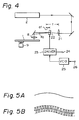
- Fig. 4 shows another embodiment of the present invention.
- the modulation and deflection are performed by a single device (called a light modulation deflector) different from the foregoing embodiment in which the different light modulator 3 and light deflector 6 are independently used.
- the recording beam from the laser 2 is input to a light modulation deflector 22 through an intermediate lens 21.
- the light modulation deflector 22 uses the acoustic optical effect.
- the intermediate lens 21 is provided to focus the spot size.
- the position of a focal distance F of the intermediate lens 21 and the center of the light modulation deflector 22 are away from each other by only a distance of d f . Even if the light modulation defector 22 performs the deflection on the focal point of the intermediate lens 21, the wobbling is not executed on the disc 1. As the distance d f is set to a large value, a wobbling amount on the disc increases.
- d f is determined in accordance with the necessary wobbling amount.
- ⁇ d denotes a deflecting angle.
- a high frequency signal from a driver 23 is supplied to the light modulation deflector 22.
- An EFM signal (pulse signal) is supplied from a terminal 24 to the driver 23.
- An output signal of the driver 23 is turned on/off in accordance with the logic levels of "0" and “1" of the EFM signal.
- the signal of the "1" level of the EFM signal from the terminal 24 is supplied.
- the EFM signal is set to the "0" level, the output signal of the driver 23 is turned off and the recording beam is not irradiated onto the disc 1.
- the pit corresponding to the EFM signal supplied from the terminal 24 is formed on the disc 1.
- the high frequency signal from a VCO 25 is supplied to the driver 23.
- a control signal from a terminal 26 is supplied to the VCO 25.
- this control signal is the signal having the frequency of 22.05 kHz as shown in Fig. 5A.
- this control signal is the multiplexed signal of the signal of 22.05 kHz and the signal of 5 MHz as shown in Fig. 5B.
- the VCO 25 has a center frequency of, e.g., 224 MHz. A frequency of an output signal of the VCO 25 changes in accordance with a signal from the terminal 26.
- the output signal of the VCO 25 is supplied to the light modulation deflector 22 through the driver 23, so that the wobbling is performed and the wide groove is formed.
- both of pits and a wide groove are formed on a disc (mother disc)
- both of them can be formed by using a single recording beam. Therefore, different from the apparatus which independently uses different recording beams, the following advantages are obtained.
- the width is electrically controlled and a groove of a desired width can be easily formed.
Landscapes
- Physics & Mathematics (AREA)
- Optics & Photonics (AREA)
- Engineering & Computer Science (AREA)
- Manufacturing & Machinery (AREA)
- Optical Recording Or Reproduction (AREA)
- Optical Head (AREA)
- Manufacturing Optical Record Carriers (AREA)
Claims (6)
- Optische Aufzeichnungsvorrichtung zur Ausbildung von Pits (31) und einer Nachlaufrille (32) auf einer optisch beschreibbaren Platte (1), bei der gemäß ihrer Ausführungsform Rillenabschnitte als Nachlauf-Servoinformation dienen und optische Information als Reihe von Vertiefungen aufgezeichnet ist, deren An- oder Abwesenheit die aufgezeichnete Information codiert,
mit einer Einrichtung (2) zur Erzeugung eines Aufzeichnungsstrahls mit vorbestimmtem Fokusdurchmesser, so daß ein Muster vorbestimmter Breite auf der Platte (1) ausgebildet werden kann,
mit einer im optischen Weg angeordneten Lichtmodulationseinrichtung (3) zum Ein- und Ausschalten des Aufzeichnungsstrahls, so daß auf der Platte ein diskretes Informationsmuster in Form einer Reihe von Pits (31) mit der vorbestimmten Breite ausgebildet werden kann,
mit einer Einrichtung zum Erzeugen einer Rille (32), die breiter als das Muster mit der vorbestimmten Breite ist,
und mit einer im optischen Weg der Einrichtung (2) zur Erzeugung des Aufzeichnungsstrahls angeordneten Lichtbeugungseinrichtung (6),
dadurch gekennzeichnet,
daß die Einrichtung zum Erzeugen einer Rille eine Antriebseinrichtung (10, 11, 12) zum Antreiben der Lichtbeugungseinrichtung (6) umfaßt, die den Aufzeichnungsstrahl in radialer Richtung der Platte (1) mit hoher Frequenz hin- und herbewegt und so bewirkt, daß die Platte (1) aufgrund dieser radialen Bewegung des Aufzeichnungsstrahls mehrfach durch den Aufzeichnungsstrahl belichtet wird, so daß die Rille (32) durch denselben Aufzeichnungsstrahl wie die Reihe von Pits mit der vorbestimmten Breite ausgebildet wird. - Vorrichtung nach Anspruch 1, wobei die hohe Frequenz f₀ durch die Gleichung

gegeben ist, wenn v die relative Geschwindigkeit zwischen dem Aufzeichnungsstrahl und der Platte (1) aufgrund der Drehung der Platte ist und d den Fokusdurchmesser des Aufzeichnungsstrahls bezeichnet. - Vorrichtung nach Anspruch 1 oder 2, wobei die Antriebseinrichtung (10, 11, 12) gemäß ihrer Anordnung die Lichtbeugungseinrichtung (6) antreibt, so daß der Aufzeichnungsstrahl in der radialen Richtung der Platte (1) mit der hohen Frequenz hin- und herbewegt wird, um die Platte (1) aufgrund dieser radialen Bewegung des Aufzeichnungsstrahls mehrfach zu belichten, und daß der Aufzeichnungsstrahl in der radialen Richtung der Platte (1) mit einer niedrigen Frequenz hin- und herbewegt wird, wodurch die Nachlaufrille, die breiter als das Muster mit der vorbestimmten Breite sowie das diskrete Informationsmuster ist, wobbelnd erzeugt wird.
- Vorrichtung nach Anspruch 1, 2 oder 3, wobei die Lichtbeugungseinrichtung und die Lichtmodulationseinrichtung aus einer einzigen akustooptischen Einrichtung (22) bestehen.
- Vorrichtung nach Anspruch 4, die zusätzlich eine Linse (21) zur Fokussierung des in die akustooptische Einrichtung (22) eintretenden Strahls aufweist.
- Verfahren zur Ausbildung von Pits (31) und einer Nachlaufrille (32) auf einer optisch beschreibbaren Platte (1), bei der gemäß ihrer Ausführungsform Rillenabschnitte als Nachlauf-Servoinformation dienen und optische Information als Reihe von Vertiefungen aufgezeichnet ist, deren An- oder Abwesenheit die aufgezeichnete Information codiert, umfassend
die Erzeugung eines Aufzeichnungsstrahls mit vorbestimmtem Fokusdurchmesser, so daß ein Muster vorbestimmter Breite auf der Platte (1) ausgebildet werden kann,
die Strahlmodulation zum Ein- und Ausschalten des Aufzeichnungsstrahls, so daß auf der Platte ein diskretes Informationsmuster in Form einer Reihe von Pits (31) mit der vorbestimmten Breite ausgebildet werden kann,
das Ausbilden einer Rille (32), die breiter als das Muster mit der vorbestimmten Breite ist,
dadurch gekennzeichnet,
daß der Schritt der Ausbildung einer Rille das Hin- und Herbewegen des Aufzeichnungsstrahls in radialer Richtung der Platte (1) mit hoher Frequenz und damit die mehrfache Belichtung der Platte (1) durch den Aufzeichnungsstrahl aufgrund dieser radialen Bewegung des Aufzeichnungsstrahls umfaßt, so daß die Rille durch denselben Aufzeichnungsstrahl wie die Reihe von Pits mit der vorbestimmten Breite ausgebildet wird.
Applications Claiming Priority (2)
| Application Number | Priority Date | Filing Date | Title |
|---|---|---|---|
| JP62192229A JP2643159B2 (ja) | 1987-07-31 | 1987-07-31 | 光学的記録方法 |
| JP192229/87 | 1987-07-31 |
Publications (3)
| Publication Number | Publication Date |
|---|---|
| EP0301865A2 EP0301865A2 (de) | 1989-02-01 |
| EP0301865A3 EP0301865A3 (de) | 1991-01-09 |
| EP0301865B1 true EP0301865B1 (de) | 1994-05-18 |
Family
ID=16287811
Family Applications (1)
| Application Number | Title | Priority Date | Filing Date |
|---|---|---|---|
| EP88306972A Expired - Lifetime EP0301865B1 (de) | 1987-07-31 | 1988-07-28 | Optisches Aufnahmegerät und optische Platte |
Country Status (6)
| Country | Link |
|---|---|
| US (2) | US4982398A (de) |
| EP (1) | EP0301865B1 (de) |
| JP (1) | JP2643159B2 (de) |
| KR (1) | KR970007745B1 (de) |
| AT (1) | ATE105962T1 (de) |
| DE (1) | DE3889598T2 (de) |
Families Citing this family (19)
| Publication number | Priority date | Publication date | Assignee | Title |
|---|---|---|---|---|
| JPH0447535A (ja) * | 1990-06-15 | 1992-02-17 | Pioneer Electron Corp | 光学的記録方法 |
| JPH04276315A (ja) * | 1991-03-01 | 1992-10-01 | Pioneer Electron Corp | 光学式記録媒体の初期化装置 |
| US5537379A (en) | 1991-05-10 | 1996-07-16 | Discovision Associates | Optical data storage and retrieval system and method |
| JPH0528507A (ja) * | 1991-07-19 | 1993-02-05 | Pioneer Electron Corp | 光学式情報記録媒体およびその再生装置 |
| JP3273444B2 (ja) * | 1992-09-21 | 2002-04-08 | 株式会社ニコン | 書込み可能な光ディスク |
| JP3221100B2 (ja) * | 1992-10-30 | 2001-10-22 | ソニー株式会社 | 光ディスク |
| US5696755A (en) * | 1992-11-04 | 1997-12-09 | Storage Technology Corporation | System for minimizing the effects of scratches on recording media |
| US5835478A (en) * | 1995-06-15 | 1998-11-10 | Sony Corporation | Optical disc having address information for recording and reproducing data at correct positions |
| DE19537406A1 (de) * | 1995-10-09 | 1997-04-10 | Leybold Ag | Vorrichtung zum Belichten eines kreisscheibenförmigen Substrates |
| US6052358A (en) * | 1996-10-04 | 2000-04-18 | Sony Corporation | Head feeding mechanism and optical pick-up feeding mechanism |
| US5757756A (en) * | 1996-10-15 | 1998-05-26 | Eastman Kodak Company | Reducing mark length variations in recording data in wobbled groove storage media |
| CN1145936C (zh) * | 1996-10-22 | 2004-04-14 | 株式会社日立制作所 | 表示磁道摆动信息的信息记录媒体及信息记录重放装置 |
| JPH10289475A (ja) * | 1997-04-16 | 1998-10-27 | Sony Corp | 露光装置 |
| JPH10334503A (ja) * | 1997-05-28 | 1998-12-18 | Sony Corp | 光ディスク原盤の露光装置 |
| JP3809715B2 (ja) * | 1997-10-28 | 2006-08-16 | ソニー株式会社 | 光情報記録媒体、光情報記録方法及び光情報記録装置 |
| TW476957B (en) | 1999-09-08 | 2002-02-21 | Mitsubishi Chem Corp | Rewritable compact disk and manufacturing method thereof |
| JP2002074664A (ja) * | 2000-08-31 | 2002-03-15 | Sony Corp | 記録装置および方法、再生装置および方法、並びに記録媒体 |
| US7268794B2 (en) * | 2000-10-30 | 2007-09-11 | Yamaha Corporation | Method of printing label on optical disk, optical disk unit, and optical disk |
| EP1965382A1 (de) | 2007-03-02 | 2008-09-03 | Singulus Mastering B.V. | Laserstrahlaufzeichnungsgerät mit akustooptischem Modulator |
Family Cites Families (6)
| Publication number | Priority date | Publication date | Assignee | Title |
|---|---|---|---|---|
| DE2038453B2 (de) * | 1970-08-01 | 1972-09-07 | Teldec Telefunken Decca Schallplat ten GmbH, 2000 Hamburg | Verfahren zur aufzeichnung hochfrequenter signale, insbesondere von videosignalen auf signaltraeger |
| NL7802860A (nl) * | 1978-03-16 | 1979-09-18 | Philips Nv | Registratiedragerlichaam en registratiedrager voor optische informatie en inrichting voor het inschrijven en uitlezen. |
| JPS5965951A (ja) * | 1982-10-08 | 1984-04-14 | Toshiba Corp | 情報記憶媒体用原盤 |
| US4716560A (en) * | 1984-05-22 | 1987-12-29 | Victor Company Of Japan, Ltd. | Recording disc and method for fabricating same |
| JPS61214246A (ja) * | 1985-03-20 | 1986-09-24 | Matsushita Electric Ind Co Ltd | 平板状情報記録担体 |
| JP2506642B2 (ja) * | 1985-10-02 | 1996-06-12 | 松下電器産業株式会社 | 情報記録原盤記録方法 |
-
1987
- 1987-07-31 JP JP62192229A patent/JP2643159B2/ja not_active Expired - Fee Related
-
1988
- 1988-07-28 EP EP88306972A patent/EP0301865B1/de not_active Expired - Lifetime
- 1988-07-28 DE DE3889598T patent/DE3889598T2/de not_active Expired - Lifetime
- 1988-07-28 AT AT88306972T patent/ATE105962T1/de not_active IP Right Cessation
- 1988-07-29 US US07/225,917 patent/US4982398A/en not_active Ceased
- 1988-07-30 KR KR1019880009696A patent/KR970007745B1/ko not_active Expired - Fee Related
-
1992
- 1992-08-03 US US07/926,511 patent/USRE34719E/en not_active Expired - Lifetime
Also Published As
| Publication number | Publication date |
|---|---|
| KR970007745B1 (ko) | 1997-05-16 |
| USRE34719E (en) | 1994-09-06 |
| DE3889598D1 (de) | 1994-06-23 |
| DE3889598T2 (de) | 1994-09-01 |
| ATE105962T1 (de) | 1994-06-15 |
| KR890002839A (ko) | 1989-04-11 |
| EP0301865A3 (de) | 1991-01-09 |
| US4982398A (en) | 1991-01-01 |
| EP0301865A2 (de) | 1989-02-01 |
| JP2643159B2 (ja) | 1997-08-20 |
| JPS6435742A (en) | 1989-02-06 |
Similar Documents
| Publication | Publication Date | Title |
|---|---|---|
| EP0301865B1 (de) | Optisches Aufnahmegerät und optische Platte | |
| JP2869147B2 (ja) | 光学式情報記録媒体 | |
| US7054260B2 (en) | Hybrid discs | |
| US5043965A (en) | Optical apparatus for optical information recording medium | |
| DE60131491T2 (de) | Optisches Aufzeichnungsmedium, Matrizenplatte zur Herstellung des optischen Aufzeichnungsmediums, und optisches Aufzeichnungs- und/oder -Wiedergabegerät | |
| US20030193875A1 (en) | Hybrid discs | |
| US6975578B2 (en) | Optical recording medium with grooves, optical recording medium master with grooves, apparatus for manufacturing optical recording medium master with grooves, and optical recording/reproducing apparatus | |
| KR20020087426A (ko) | 광 기록 매체, 광 기록 매체 제조용 원반, 광 기록 매체제조용 원반의 제조장치, 광 기록 매체 제조용 원반의제조 방법 | |
| JP3164543B2 (ja) | ディスク状記録媒体 | |
| JP2002298445A (ja) | 光記録媒体及び光記録媒体製造用原盤 | |
| JP3068878B2 (ja) | 光ディスク原盤の作製方法 | |
| JP2960018B2 (ja) | 円盤状記録媒体 | |
| JP2869146B2 (ja) | 光学式情報記録媒体 | |
| JPH1153772A (ja) | 光記録媒体及び光学カッティング方法、光学カッティング装置 | |
| JP2941366B2 (ja) | 露光装置の光ビーム強度調整方法 | |
| KR100186292B1 (ko) | 광디스크 스탬퍼 제조를 위한 노광방법 및 그 장치 | |
| JPH09320127A (ja) | 光学記録方法、光学記録装置及び光学記録媒体 | |
| JP2748894B2 (ja) | 露光装置 | |
| JPH0719397B2 (ja) | 光ディスク製造装置 | |
| JPH1131331A (ja) | 光ディスク原盤製造装置 | |
| JPH04362549A (ja) | 光ディスク原盤露光装置 | |
| EP1965382A1 (de) | Laserstrahlaufzeichnungsgerät mit akustooptischem Modulator | |
| JPH11306602A (ja) | 情報記録媒体作製用原盤および情報記録媒体の各製造方法と露光装置 | |
| JPH09231566A (ja) | 光ディスク原盤露光機及び光ディスク原盤製造方法 | |
| HK1065160A (en) | Improved hybrid discs, and methods and apparatus for their manufacture |
Legal Events
| Date | Code | Title | Description |
|---|---|---|---|
| PUAI | Public reference made under article 153(3) epc to a published international application that has entered the european phase |
Free format text: ORIGINAL CODE: 0009012 |
|
| AK | Designated contracting states |
Kind code of ref document: A2 Designated state(s): AT DE FR GB |
|
| PUAL | Search report despatched |
Free format text: ORIGINAL CODE: 0009013 |
|
| RHK1 | Main classification (correction) |
Ipc: G11B 7/00 |
|
| AK | Designated contracting states |
Kind code of ref document: A3 Designated state(s): AT DE FR GB |
|
| 17P | Request for examination filed |
Effective date: 19910607 |
|
| 17Q | First examination report despatched |
Effective date: 19920506 |
|
| GRAA | (expected) grant |
Free format text: ORIGINAL CODE: 0009210 |
|
| AK | Designated contracting states |
Kind code of ref document: B1 Designated state(s): AT DE FR GB |
|
| REF | Corresponds to: |
Ref document number: 105962 Country of ref document: AT Date of ref document: 19940615 Kind code of ref document: T |
|
| REF | Corresponds to: |
Ref document number: 3889598 Country of ref document: DE Date of ref document: 19940623 |
|
| ET | Fr: translation filed | ||
| PLBE | No opposition filed within time limit |
Free format text: ORIGINAL CODE: 0009261 |
|
| STAA | Information on the status of an ep patent application or granted ep patent |
Free format text: STATUS: NO OPPOSITION FILED WITHIN TIME LIMIT |
|
| 26N | No opposition filed | ||
| REG | Reference to a national code |
Ref country code: GB Ref legal event code: IF02 |
|
| PGFP | Annual fee paid to national office [announced via postgrant information from national office to epo] |
Ref country code: DE Payment date: 20070726 Year of fee payment: 20 |
|
| PGFP | Annual fee paid to national office [announced via postgrant information from national office to epo] |
Ref country code: AT Payment date: 20070711 Year of fee payment: 20 |
|
| PGFP | Annual fee paid to national office [announced via postgrant information from national office to epo] |
Ref country code: GB Payment date: 20070725 Year of fee payment: 20 |
|
| PGFP | Annual fee paid to national office [announced via postgrant information from national office to epo] |
Ref country code: FR Payment date: 20070710 Year of fee payment: 20 |
|
| REG | Reference to a national code |
Ref country code: GB Ref legal event code: PE20 Expiry date: 20080727 |
|
| PG25 | Lapsed in a contracting state [announced via postgrant information from national office to epo] |
Ref country code: GB Free format text: LAPSE BECAUSE OF EXPIRATION OF PROTECTION Effective date: 20080727 |