EP0301886A2 - Pompe récupérant l'énergie à engrenages avec refoulement variable - Google Patents
Pompe récupérant l'énergie à engrenages avec refoulement variable Download PDFInfo
- Publication number
- EP0301886A2 EP0301886A2 EP88307011A EP88307011A EP0301886A2 EP 0301886 A2 EP0301886 A2 EP 0301886A2 EP 88307011 A EP88307011 A EP 88307011A EP 88307011 A EP88307011 A EP 88307011A EP 0301886 A2 EP0301886 A2 EP 0301886A2
- Authority
- EP
- European Patent Office
- Prior art keywords
- area
- demeshing
- inlet
- outlet
- chamber
- Prior art date
- Legal status (The legal status is an assumption and is not a legal conclusion. Google has not performed a legal analysis and makes no representation as to the accuracy of the status listed.)
- Withdrawn
Links
Images


Classifications
-
- F—MECHANICAL ENGINEERING; LIGHTING; HEATING; WEAPONS; BLASTING
- F04—POSITIVE - DISPLACEMENT MACHINES FOR LIQUIDS; PUMPS FOR LIQUIDS OR ELASTIC FLUIDS
- F04C—ROTARY-PISTON, OR OSCILLATING-PISTON, POSITIVE-DISPLACEMENT MACHINES FOR LIQUIDS; ROTARY-PISTON, OR OSCILLATING-PISTON, POSITIVE-DISPLACEMENT PUMPS
- F04C14/00—Control of, monitoring of, or safety arrangements for, machines, pumps or pumping installations
- F04C14/24—Control of, monitoring of, or safety arrangements for, machines, pumps or pumping installations characterised by using valves controlling pressure or flow rate, e.g. discharge valves or unloading valves
- F04C14/26—Control of, monitoring of, or safety arrangements for, machines, pumps or pumping installations characterised by using valves controlling pressure or flow rate, e.g. discharge valves or unloading valves using bypass channels
Definitions
- the present invention relates generally to variable discharge gear pumps and more specifically to a variable discharge gear pump having energy recovery.
- Gear pumps generally include a pair of oppositely rotating gears having an intermeshed area between an inlet and an outlet.
- the meshing teeth of the gears open on the inlet side filling the pockets and carrying fluid around to the outlet side.
- the teeth mesh on the outlet side creating a positive pressure and demesh on the inlet side creating a negative pressure.
- the axes of the pair of gears are fixed and parallel to each other.
- U.S. Patent No. 2,481,646 to Conklin is a typical example of a variable delivery gear pump wherein high pressure fluid from the outlet side is adjustably connected to the pockets of the gear on the inlet side.
- the number of pockets that are prefilled with fluid from the outlet side of the pump are selected. This not only bypasses fluid from the outlet to the inlet, but also provides it directly at the open pockets and therefore varies the throughput.
- variable delivery gear pumps wherein the axes of the parallel gears are fixed and fluid is fed back from the output to the input, they fail to recognize the ability to recover energy and substantially reduce the amount of torque needed to drive the gear pump.
- the two discussed Svenson patents although removing fluid from the meshing and providing fluid to the demeshing area of the gears, as well as providing a bypass of outlet fluid to the inlet, the structure of the fluid passages are such that they fail to provide high pressure fluid at the demeshing area of the intermeshing teeth and therefore also does not recover energy.
- U.S. Patent No. 3,669,577 to Swanson is an example of a variable displacement gear pump wherein the gears move axially relative to each other to vary the displacement.
- This patent also includes radial channels in the teeth of the gears to receive fluid from the inlet chamber and to propel it under centrifugal force into the opening areas on the demeshing gear side to relieve the vacuum of the demeshing gears to thereby reduce vaporization and consequently improve the efficiency of the pump. These channels are not used to effect the displacement of the pump, nor recover energy since the fluid in the channels of the gears are cut off from the high pressure outlet fluid.
- variable discharge gear pump of the fixed axis design which includes variable energy recovery.
- variable discharge gear pump having fixed gear displacement which includes energy recovery.
- Another object of the present invention is to provide a variable discharge gear pump having variable energy recovery.
- a still further object of the present invention is to provide a variable discharge gear pump and energy recovery with a minimum number of parts.
- An even further object of the present invention is to provide a large capacity pump which has the reduced loading of smaller capacity pumps.
- an outlet adjustment in fluid communication with the outlet chamber for adjustably providing high pressurized fluid from the outlet chamber to selected portions of the demeshing area of the intermeshing teeth which are between the inlet and outlet chambers to vary the discharge flow of the pump and the amount of energy recovery. This results in maintaining a positive pressure in selected portions of the meshing area as well as equalizing the pressure in the selected areas to the pressure in the outlet chamber.
- an inlet adjustment is provided connecting the inlet chamber and the demeshing area for variably controlling the flow therebetween.
- the inlet and outlet adjustments are coordinated whereby fluid flow between the inlet chamber and the demeshing area decreases with decreasing discharge flow to thereby increase the energy recovery.
- the inlet adjustment controls the primary flow between the inlet chamber and the demeshing area. This adjustment, by decreasing the flow communication to the inlet chamber, allows greater pressure to build up in the demeshing area and thereby increase energy recovery.
- the inlet and outlet adjustments include a common spool having a channel and an inlet land.
- the channel in the spool connecting the outlet and the intermeshing areas is of sufficient dimension to assure that sufficient fluid of high pressure is provided in selected portions of the demeshing area of the gears.
- This channel is a recess, slot or undercut in the spool which is in continuous communication with the outlet chamber.
- the inlet land varies the primary fluid flow between the inlet chamber and the demeshing area.
- the spool is positioned rectilinearly along an axis to align the slot in communication with the selected portions of the intermeshing areas and vary the inlet primary fluid flow.
- the width of the slot is substantially equal to the height of the teeth of the gears so as to overlap teeth in the intermeshing area and not reduce the pressure available from the outlet chamber.
- the axis of rectilinear movement of the spool is perpendicular to the plane of the parallel axis of rotation of the pair of gears and is equidistant from the parallel axis.
- the slot extends from the outlet chamber and over contiguous portions of the meshing and demeshing areas as adjusted.
- Secondary channels continuously connect the inlet to the gear teeth exterior the intermeshing area for preventing cavitation without decreasing energy recovery.
- the required torque is reduced by using the high pressure outlet energy to minimize the pressure differential between the meshing and demeshing areas of the intermeshing gear teeth and decreasing the fluid connecting to the inlet chamber. Pressurizing the inlet meshing area also helps pressure balance the gears reducing mechanical torque, journal loading and heat during the discharge flow reduction.
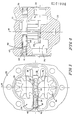
- a gear pump as shown in Figure 1, includes a housing 20, having a pair of intermeshing gears 22 and 24 rotated about parallel fixed axes in opposite directions.
- the gears 22 and 24 are positioned between an inlet chamber 26 and an outlet chamber 28 of the pump.
- the intermeshing gears have a center line M with a meshing area of decreasing displacement of the teeth on the outlet side to the right of the center line M as is depicted in Figure 1, and a demeshing area of increasing displacement of the teeth on the inlet side or to the left of center line M.
- the average differential pressure between the meshing and demeshing areas of the intermeshing teeth plus mechanically induced torque determines the overall torque required to drive the gears 22 and 24.
- FIGs 7-14 show graphs of the pressure and torque for various pumps of the prior art and the invention. The pressure profile is shown in the solid line and the required operating torque is shown in the dashed line. These graphs are Comparisons only and have typical inlet and discharge pressures (atmospheric inlet pressure is used).
- FIGS 8-10 represent bypasses of prior art and the invention with typical bypass flow and pressure.
- a standard pump with bypass to tank has no profile change so it remains as shown in Figure 7.
- FIG. 9 Another typical bypass structure, illustrated by Figure 9, is that of U.S. Patent No. 1,912,737. Because of its specific structure, the communication of a fluid between the meshing and demeshing areas is restricted and the amount of fluid flowing from and to the meshing and demeshing areas is a function of the speed of operation. Thus, fluid is not freely flowing to maintain the demeshing areas filled with high pressure fluid. So, there is still a substantial pressure differential between the meshing and demeshing area. There is a minimal reduction in torque required over the standard pump with bypass to inlet of Figure 8.
- the present invention of Figure 2 is designed to achieve the pressure and torque profile of Figure 10 during partial bypass.
- the pressure profile on the discharge meshing area is substantially flat with a small rise approaching the center M of the intermeshing area. This is produced by a minimum amount of restriction in the intermeshing teeth.
- the pressure on the inlet demeshing area begins substantially at this pressure and decreases, in the manner shown in Figure 10, to the pump inlet. By reducing the pressure differential of the meshing and demeshing areas, the required torque is substantially less than that of the Figures of the prior art.
- FIG 11-14 are graph comparisons of prior art and the invention in the standby or full bypass mode. In this mode there is a small amount of discharge flow diverted to tank, in some means, at a low pressure to provide cooling during this mode. Standby or full bypass mode is when there is no requirement for discharge flow to operate a function. The graphs are shown with typical discharge and inlet pressures as in previous graphs.
- Figure 11 shows a standard pump with bypass to inlet in the standby mode. This graph shows no change in the discharge meshing area and a small change in the inlet meshing area which reduces the torque requirement slightly over the bypass to tank pump illustrated again in Figure 7.
- Figure 12 illustrates the pump of U.S. Patent No. 1,912,737 in full bypass and shows an improvement in torque requirement over Figures 11 and 7, yet it is still minimal in comparison to the invention.
- Figure 14 is the invention of Figure 3 in standby and shows a substantial decrease in the differential pressure between the meshing and demeshing area and a marked improvement in the torque requirement compared to prior art.
- a positive high pressure fluid must be provided in the intermeshing area. This is achieved by providing a communication between the outlet chamber, the meshing area, and the demeshing area in an attempt to provide more than enough fluid into the demeshing area and attempt to equalize the pressure thereacross, by reducing the differential pressure between the meshing and demeshing areas, and substantially removing the negative pressure portion on the demeshing side, thereby creating a positive pressure on the demeshing area, energy recovery is possible. This produces a substantial reduction in the required torque. In the ideal case, the positive pressure in the demeshing area if maintained as high as possible, would result in a torque requirement proportional to the discharge flow. This does not account for the mechanical and heat losses in the system.
- a spool 30, as illustrated in Figure 1-4, is provided externally between the inlet chamber 26 and the outlet chamber 28 and across the intermeshing area. Slots 32 and 34 in the spool 30 are in the outlet and inlet chamber respectively.
- the spool 30 has a first end 38 lying in a signal pressure chamber 36.
- the other end 42 of spool 30 lying in pressure chamber 41 is biased opposite the pressure in chamber 36 by a spring 40.
- the spool 30 moves rectilinearly along an axis which is perpendicular to the parallel axis of rotation of gears 22 and 24 and is equidistant to the parallel axis of rotation of the gears 22 and 24.
- the spring 40 lies within a bore 43 in the end 42 of the spool 30. Since the recess 34 is an anti-trapping recess and is an optional feature which may be deleted, the bore 43 will then be isolated from the inlet chamber 26 and therefore capable of sealing chamber 41 with respect to the inlet chamber 26. Thus, chamber 41 may receive a control pressure such that the spool 30 can be positioned based on the differential pressure between the chamber 41 on the left side of the spool and chamber 36 on the right side of the spool. As a further alternative, the bore 43 may be eliminated and the spring 41 may engage the outermost face of the end 42 such that an anti-trapping recess 34 may be provided and the pressure chamber 41 may also be isolated from the valve inlet chamber 26.
- the primary inlet fluid flow is between the inlet chamber 26 and the edges of the gear teeth.
- the anti-trapping recess 34 merely provides a secondary connection between the inlet chamber 26 and the demeshing area along the face of the gears.
- the anti-trapping recess 34 have little if any effect on the primary inlet fluid flow to the demeshing teeth, although it does aid in providing inlet fluid to the demeshing area to minimize the formation of a vacuum when there is no bypass or little bypass as in Figures 1 and 2.
- the spool is in its right-most position which corresponds to full pump discharge, with no energy recovery.
- the length of the slot 32 is sufficient such that it is in constant communication with the outlet chamber 28.
- slot 32 communicates with the meshing area of teeth 22 and 24 so as to equalize the pressure in the meshing section with the pressure in the outlet chamber 28.
- Recess 34 in the inlet side of spool 30 is positioned in its right-most position of the demeshing area and attempts to equalize the pressure in the pump inlet chamber 26 with the demeshing area of the gear teeth. This more quickly dissipates the vacuum created by the demeshing teeth and thereby helps to reduce the drag produced by the vacuum.
- FIGs 5 and 6 An enlarged view of the relationship of the relation of the slot 32 of the spool 30 and the intermeshing area of the teeth is illustrated in Figures 5 and 6.
- the gears are shown as being transparent so as to illustrate the juxtaposition of the elements and their operation.
- teeth A and C of gear 22 mate and intermesh with teeth B and D of gear 24 to provide an effectively sealed volume F therebetween on the left side of the center line M.
- the slot 32 extends from the outlet across the total meshing area and extends slightly past M into the demeshing area.
- the width of the slot 32 is substantially large so as to not restrict the transmission of pressure from the outlet chamber 28 to the intermeshing areas. As illustrated specifically in Figure 6, the width W of the slot 32 extending substantially across the height of the intermeshing of the teeth and being substantially equal to the height of the tooth H illustrated for tooth B.
- the substantially sealed volume F of the intermeshing teeth has a substantial constant area extending on the demeshing side of the center line M.
- the high pressure in the outlet is provided in the volume F. This high pressure causes force of separation on the demeshing side of the center line M and thereby generates an energy recovery force.
- the amount of fluid transmitted from the outlet through slot 32 to the demeshing side of the gears reduces the amount of fluid being discharged.
- slot 32 of the spool serves simultaneously as an adjustment of the discharge of the variable discharge pump as well as to determine the amount of energy recovery.
- the spool 30 is at the same location with slot 32 extending slightly past the center line M into the demeshing area and the gears 22 and 24 have rotated a degree or two. Tooth B extends deeper into the area between teeth C and A which would normally substantially compress the fluid therein. With the slot 32 extending substantially to the top of the tooth B in the bottom of the valley between teeth A and C, excessive pressure of compression is equalized with the outlet chamber pressure.
- the slot 32 extends from the outlet across contiguous portions of the meshing area and the demeshing area.
- the spool 30 is preferably rectangular and moves in a rectilinear direction across the side of the intermeshing area of the gears. This particular configuration was selected so as to maximize the transfer of fluid under pressure from the outlet chamber 28 to selected portions of the meshing and demeshing gear teeth so as to provide fluid under pressure into the selected areas of the teeth to recover energy and reduce required torque. It should also be noted that a pair of spools may be provided on each face of the gears.
- Another benefit of minimizing the differential pressure in the mesh area during flow reduction, is that it minimizes the heat generation in this area.
- Larger pumps which have larger teeth width experience sideloading which requires more torque and loading on the bearings.
- the sideloading comes from the large differential pressure between the inlet and the outlet side.
- the present invention by providing a high pressure fluid in the demeshing side, provides a force counter to the side loading force. This reduces side loading and, in the bypass mode, causes the large capacity pumps to have a reduced loading which is similar to that experienced by small capacity pumps.
- the embodiment of Figures 15-17 increase the pressure in the demeshing area with decreasing delivery or conversely increasing bypass by providing an inlet adjustment.
- the bypassed outlet fluid meets greater resistance to escaping towards the inlet and therefore, a greater buildup in pressure in the demeshing area is produced. This substantially increases the amount of energy recovery or conversely, reduces the amount of torque needed to drive the gear pump.
- the housing 20 of the gear pump is modified such that the inlet chamber 26 is connected to the demeshing area primarily through a bore 29.
- the end 42 or land of the spool 30 slides within the bore 29 and controls the interconnection between the inlet chamber 26 and the demeshing area of gear teeth 22 and 24.
- the spool 30 in Figures 15-17 as compared to the spool in Figures 1-4, includes a stop 44 extending from the inlet end 42 of the spool 30 which, as illustrated in Figure 16, engages the housing at the full bypass position.
- the stop 44 also forms a guide for the spring 40.
- the slot 32 of the spool 30 is not an interior slot as in Figures 1-4, but is produced by circumferially reducing the diameter of the spool to create a circumferial recess or slot between the lands 38 and 40 of the spool 30.
- the recess 32 does not extend across the center line M and therefore the outlet 28 is only connected to the meshing teeth.
- the land 44 is in its fully rightward position allowing full communication between the inlet chamber 26 and the demeshing area of the teeth through bore 29.
- the recess 32 connects the outlet 28 to the meshing and demeshing area equalizing pressure thereacross.
- the land 42 slides in bore 29 completely blocking the inlet chamber 26 from the demeshing area. This prevents the fed-back high pressure fluid from the outlet from escaping back into the inlet and thereby maximizes the pressure in the demeshing area and increases energy recovery.
- a comparison between the graphs of Figures 14 and 18 will indicate the increase in pressure in the demeshing area.
- the recess 32 is positioned so that it extends across the center line M providing high pressurized fluid from the outlet 28 to the meshing and demeshing area causing a bypass.
- the land 42 at the inlet begins to restrict the outlet of bore 29 as compared to that of Figure 15. This restricts the ability of the bypass fluid from flowing freely to the inlet and thereby increases the pressure in the demeshing area.
- the result of providing the inlet control can be seen from comparing Figure 19 with Figure 10.
- a pair of channels 46 are shown connecting the inlet chamber 26 and the gear teeth 22 and 24 outside the demeshing area. This prevents cavitation in the gear teeth as they travel towards the outlet 28 which may result from the use of the land 42 as an inlet control valve. Also, at high speeds irrespective of the position of the inlet control portion 42 of the spool 30, they will also prevent cavitation.
- the channels 46 provide secondary flow in Figures 15-17, they may also be added to the embodiment of Figures 1-4.
Landscapes
- Engineering & Computer Science (AREA)
- Physics & Mathematics (AREA)
- Fluid Mechanics (AREA)
- Mechanical Engineering (AREA)
- General Engineering & Computer Science (AREA)
- Details And Applications Of Rotary Liquid Pumps (AREA)
- Rotary Pumps (AREA)
Applications Claiming Priority (4)
| Application Number | Priority Date | Filing Date | Title |
|---|---|---|---|
| US79010 | 1987-07-29 | ||
| US07/079,010 US4824331A (en) | 1987-07-29 | 1987-07-29 | Variable discharge gear pump with energy recovery |
| US220234 | 1988-07-20 | ||
| US07/220,234 US4902202A (en) | 1987-07-29 | 1988-07-20 | Variable discharge gear pump with energy recovery |
Publications (2)
| Publication Number | Publication Date |
|---|---|
| EP0301886A2 true EP0301886A2 (fr) | 1989-02-01 |
| EP0301886A3 EP0301886A3 (fr) | 1990-03-14 |
Family
ID=26761517
Family Applications (1)
| Application Number | Title | Priority Date | Filing Date |
|---|---|---|---|
| EP88307011A Withdrawn EP0301886A3 (fr) | 1987-07-29 | 1988-07-29 | Pompe récupérant l'énergie à engrenages avec refoulement variable |
Country Status (4)
| Country | Link |
|---|---|
| US (1) | US4902202A (fr) |
| EP (1) | EP0301886A3 (fr) |
| JP (1) | JPH01290979A (fr) |
| AU (1) | AU2016488A (fr) |
Cited By (5)
| Publication number | Priority date | Publication date | Assignee | Title |
|---|---|---|---|---|
| DE4444819A1 (de) * | 1994-12-15 | 1996-06-20 | Bayerische Motoren Werke Ag | Schmierölpumpe einer Brennkraftmaschine |
| WO1997049917A1 (fr) * | 1996-06-26 | 1997-12-31 | Robert Bosch Gmbh | Pompe d'alimentation en carburant pour une pompe d'injection de carburant pour moteur a combustion interne |
| DE19631202A1 (de) * | 1996-08-02 | 1998-02-05 | Neudecker & Jolitz Gmbh & Co | Hydraulische Zahnradpumpe, insbesondere für eine Türbetätigungsvorrichtung |
| DE19638335A1 (de) * | 1996-09-19 | 1998-04-02 | Bosch Gmbh Robert | Förderpumpe |
| WO2001090632A1 (fr) * | 2000-05-25 | 2001-11-29 | Gkn Sinter Metals Gmbh | Pompe regulee |
Families Citing this family (19)
| Publication number | Priority date | Publication date | Assignee | Title |
|---|---|---|---|---|
| US5230223A (en) * | 1992-03-20 | 1993-07-27 | Envirosystems Corporation | Method and apparatus for efficiently controlling refrigeration and air conditioning systems |
| DE4227716C2 (de) * | 1992-08-21 | 1997-07-03 | Danfoss As | Ölzuführeinrichtung für eine Brennerspeiseeinrichtung |
| US5397219A (en) * | 1993-06-21 | 1995-03-14 | C. Cretors & Company | Integral liquid pump and drainback valve |
| DE4336289A1 (de) * | 1993-10-25 | 1995-04-27 | Huels Chemische Werke Ag | Mehrschichtiges Kunststoffrohr |
| DE19625565C2 (de) * | 1996-06-26 | 1998-07-23 | Bosch Gmbh Robert | Kraftstoff-Förderpumpe für eine Kraftstoff-Einspritzpumpe für Brennkraftmaschinen |
| DE19638332C2 (de) * | 1996-09-19 | 2000-07-20 | Bosch Gmbh Robert | Förderpumpe |
| DE20021586U1 (de) * | 2000-12-21 | 2002-02-14 | Andreas Stihl AG & Co., 71336 Waiblingen | Getriebekopf |
| FR2837536B1 (fr) | 2002-03-20 | 2004-06-25 | Renault | Pompe a huile a cylindree modulable pour automobile |
| EP1617926A2 (fr) * | 2003-04-30 | 2006-01-25 | Mattel, Inc. | Canons a eau a manivelle |
| US8011910B2 (en) * | 2005-02-22 | 2011-09-06 | Limo-Reid, Inc. | Low noise gear set for gear pump |
| US20070164087A1 (en) * | 2006-01-17 | 2007-07-19 | Honeywell International, Inc. | Method for repair of housings |
| DE102006011200B4 (de) * | 2006-03-10 | 2014-11-13 | Schwäbische Hüttenwerke Automotive GmbH & Co. KG | Außenzahnradpumpe mit Entlastungstasche |
| US8464634B2 (en) * | 2007-08-14 | 2013-06-18 | C. Cretors & Company | Popcorn machines with topping dispensing systems and associated methods of use and manufacture |
| JP5397117B2 (ja) * | 2009-09-17 | 2014-01-22 | 株式会社Ihi | ギアポンプ |
| WO2015131057A2 (fr) * | 2014-02-28 | 2015-09-03 | Purdue Research Foundation | Machine à engrenage externe à débit variable |
| US10309396B2 (en) * | 2016-04-27 | 2019-06-04 | Deere & Company | Positive displacement pump including an unloading device |
| US11022115B2 (en) * | 2017-06-02 | 2021-06-01 | Purdue Research Foundation | Controlled variable delivery external gear machine |
| US11621604B2 (en) | 2020-02-16 | 2023-04-04 | Purdue Research Foundation | Integrated electro-hydraulic machine |
| CN112761941B (zh) * | 2021-01-19 | 2022-11-22 | 南通油顺液压机械有限公司 | 一种内啮合变量齿轮泵 |
Family Cites Families (10)
| Publication number | Priority date | Publication date | Assignee | Title |
|---|---|---|---|---|
| GB119130A (en) * | 1917-10-24 | 1918-09-26 | Emile Joseph Augustin Schultz | Improvements in or relating to Rotary Pumps for Fluids. |
| US2310078A (en) * | 1938-12-24 | 1943-02-02 | Vickers Inc | Pump or motor for power transmission |
| US2481646A (en) * | 1943-08-18 | 1949-09-13 | Western Electric Co | Variable delivery gear pump |
| US2498790A (en) * | 1947-12-22 | 1950-02-28 | Milo C Caughrean | Gear pump |
| US2915976A (en) * | 1952-02-01 | 1959-12-08 | Zenith Carburateur Soc Du | Gear pumps |
| US3026810A (en) * | 1956-09-12 | 1962-03-27 | Borg Warner | Variable displacement pump |
| US3023706A (en) * | 1960-03-24 | 1962-03-06 | Gen Motors Corp | Gear pump and relief valve |
| DE2554105C2 (de) * | 1975-12-02 | 1984-04-05 | Robert Bosch Gmbh, 7000 Stuttgart | Zahnradmaschine (Pumpe oder Motor) |
| US4130383A (en) * | 1977-06-23 | 1978-12-19 | Borg-Warner Corporation | Apparatus for noise suppression in a gear pump |
| FR2465907A1 (fr) * | 1979-09-26 | 1981-03-27 | Renault | Pompe hydraulique a engrenages silencieuse par amelioration des flasques |
-
1988
- 1988-07-20 US US07/220,234 patent/US4902202A/en not_active Expired - Fee Related
- 1988-07-29 EP EP88307011A patent/EP0301886A3/fr not_active Withdrawn
- 1988-07-29 JP JP63191967A patent/JPH01290979A/ja active Pending
- 1988-07-29 AU AU20164/88A patent/AU2016488A/en not_active Abandoned
Cited By (10)
| Publication number | Priority date | Publication date | Assignee | Title |
|---|---|---|---|---|
| DE4444819A1 (de) * | 1994-12-15 | 1996-06-20 | Bayerische Motoren Werke Ag | Schmierölpumpe einer Brennkraftmaschine |
| WO1997049917A1 (fr) * | 1996-06-26 | 1997-12-31 | Robert Bosch Gmbh | Pompe d'alimentation en carburant pour une pompe d'injection de carburant pour moteur a combustion interne |
| DE19631202A1 (de) * | 1996-08-02 | 1998-02-05 | Neudecker & Jolitz Gmbh & Co | Hydraulische Zahnradpumpe, insbesondere für eine Türbetätigungsvorrichtung |
| EP0822334A3 (fr) * | 1996-08-02 | 1998-11-25 | Neudecker & Jolitz GmbH & Co. | Pompe à engrenages |
| DE19638335A1 (de) * | 1996-09-19 | 1998-04-02 | Bosch Gmbh Robert | Förderpumpe |
| EP0831231A3 (fr) * | 1996-09-19 | 1999-03-03 | Robert Bosch Gmbh | Pompe à engrenages |
| DE19638335C2 (de) * | 1996-09-19 | 2000-07-20 | Bosch Gmbh Robert | Förderpumpe |
| US6116859A (en) * | 1996-09-19 | 2000-09-12 | Robert Bosch Gmbh | Pressure operated by-pass valve disposed in the cover of a feed pump for reverse flow |
| WO2001090632A1 (fr) * | 2000-05-25 | 2001-11-29 | Gkn Sinter Metals Gmbh | Pompe regulee |
| US6709245B2 (en) | 2000-05-25 | 2004-03-23 | Gkn Sinter Metals Gmbh | Regulated pump |
Also Published As
| Publication number | Publication date |
|---|---|
| US4902202A (en) | 1990-02-20 |
| JPH01290979A (ja) | 1989-11-22 |
| EP0301886A3 (fr) | 1990-03-14 |
| AU2016488A (en) | 1989-02-02 |
Similar Documents
| Publication | Publication Date | Title |
|---|---|---|
| US4902202A (en) | Variable discharge gear pump with energy recovery | |
| EP0785361B1 (fr) | Appareil de pompe à huile | |
| US4443169A (en) | Gear pump | |
| US5722815A (en) | Three stage self regulating gerotor pump | |
| EP0228817B1 (fr) | Dispositif de commande hydraulique pour transmission à réglage continu | |
| US4551080A (en) | Variable displacement sliding vane pump/hydraulic motor | |
| US5328337A (en) | Guided vanes hydraulic power system | |
| US6332522B1 (en) | Hydraulic coupling for vehicle drivetrain | |
| EP0282358B1 (fr) | Accès pour pompe volumétrique | |
| JPS61108885A (ja) | 可逆流れベーンポンプ | |
| GB2342398A (en) | Pressure relief return flow management systems in gerotor pumps | |
| EP0702154B1 (fr) | Appareil à engrènement interne | |
| GB2119446A (en) | Rotary positive-displacement gas-compressor | |
| WO1993008406A1 (fr) | Regenerateur pour un systeme de puissance a fluide | |
| EP0176269B1 (fr) | Moyens de transfert de pression de fluide pour amortissement des pulsations à un suralimenteur | |
| US4824331A (en) | Variable discharge gear pump with energy recovery | |
| GB2140872A (en) | Rotary positive-displacement fluid-machine | |
| JPH05263770A (ja) | オイルポンプ | |
| US5366354A (en) | Variable fluid volume vane pump arrangement | |
| US6238315B1 (en) | Hydraulic coupling for vehicle drivetrain | |
| US3995978A (en) | Hydraulic fluid pressure device and porting arrangement therefor | |
| US5017101A (en) | Selectively operated gerotor device | |
| CN108138763A (zh) | 叶片齿轮泵 | |
| US10316867B2 (en) | Hydraulic rotary actuator with built-in mechanical position feedback | |
| CN113236556A (zh) | 一种谐波型线的齿轮式调压油泵 |
Legal Events
| Date | Code | Title | Description |
|---|---|---|---|
| PUAI | Public reference made under article 153(3) epc to a published international application that has entered the european phase |
Free format text: ORIGINAL CODE: 0009012 |
|
| AK | Designated contracting states |
Kind code of ref document: A2 Designated state(s): DE GB IT NL SE |
|
| PUAL | Search report despatched |
Free format text: ORIGINAL CODE: 0009013 |
|
| AK | Designated contracting states |
Kind code of ref document: A3 Designated state(s): DE GB IT NL SE |
|
| STAA | Information on the status of an ep patent application or granted ep patent |
Free format text: STATUS: THE APPLICATION IS DEEMED TO BE WITHDRAWN |
|
| 18D | Application deemed to be withdrawn |
Effective date: 19900915 |