EP0302248A1 - Seringue à injection pour usage médical - Google Patents
Seringue à injection pour usage médical Download PDFInfo
- Publication number
- EP0302248A1 EP0302248A1 EP88110812A EP88110812A EP0302248A1 EP 0302248 A1 EP0302248 A1 EP 0302248A1 EP 88110812 A EP88110812 A EP 88110812A EP 88110812 A EP88110812 A EP 88110812A EP 0302248 A1 EP0302248 A1 EP 0302248A1
- Authority
- EP
- European Patent Office
- Prior art keywords
- syringe
- plunger
- piston
- wall
- cylinder
- Prior art date
- Legal status (The legal status is an assumption and is not a legal conclusion. Google has not performed a legal analysis and makes no representation as to the accuracy of the status listed.)
- Granted
Links
- 238000002347 injection Methods 0.000 title claims abstract description 12
- 239000007924 injection Substances 0.000 title claims abstract description 12
- 238000007789 sealing Methods 0.000 claims description 14
- 239000011324 bead Substances 0.000 claims description 10
- 239000000945 filler Substances 0.000 claims description 2
- 230000002093 peripheral effect Effects 0.000 claims description 2
- 238000004108 freeze drying Methods 0.000 description 23
- 239000000463 material Substances 0.000 description 5
- 239000003814 drug Substances 0.000 description 4
- 239000002904 solvent Substances 0.000 description 4
- 229940079593 drug Drugs 0.000 description 3
- 238000009423 ventilation Methods 0.000 description 3
- 230000000694 effects Effects 0.000 description 2
- 238000001035 drying Methods 0.000 description 1
- 239000013013 elastic material Substances 0.000 description 1
- 239000007788 liquid Substances 0.000 description 1
- 238000004519 manufacturing process Methods 0.000 description 1
- 238000000034 method Methods 0.000 description 1
- 238000003825 pressing Methods 0.000 description 1
- 239000000243 solution Substances 0.000 description 1
- 238000013022 venting Methods 0.000 description 1
Images

Classifications
-
- A—HUMAN NECESSITIES
- A61—MEDICAL OR VETERINARY SCIENCE; HYGIENE
- A61M—DEVICES FOR INTRODUCING MEDIA INTO, OR ONTO, THE BODY; DEVICES FOR TRANSDUCING BODY MEDIA OR FOR TAKING MEDIA FROM THE BODY; DEVICES FOR PRODUCING OR ENDING SLEEP OR STUPOR
- A61M5/00—Devices for bringing media into the body in a subcutaneous, intra-vascular or intramuscular way; Accessories therefor, e.g. filling or cleaning devices, arm-rests
- A61M5/178—Syringes
- A61M5/31—Details
- A61M5/3129—Syringe barrels
-
- A—HUMAN NECESSITIES
- A61—MEDICAL OR VETERINARY SCIENCE; HYGIENE
- A61M—DEVICES FOR INTRODUCING MEDIA INTO, OR ONTO, THE BODY; DEVICES FOR TRANSDUCING BODY MEDIA OR FOR TAKING MEDIA FROM THE BODY; DEVICES FOR PRODUCING OR ENDING SLEEP OR STUPOR
- A61M5/00—Devices for bringing media into the body in a subcutaneous, intra-vascular or intramuscular way; Accessories therefor, e.g. filling or cleaning devices, arm-rests
- A61M5/178—Syringes
- A61M5/31—Details
- A61M5/315—Pistons; Piston-rods; Guiding, blocking or restricting the movement of the rod or piston; Appliances on the rod for facilitating dosing ; Dosing mechanisms
- A61M5/31511—Piston or piston-rod constructions, e.g. connection of piston with piston-rod
-
- A—HUMAN NECESSITIES
- A61—MEDICAL OR VETERINARY SCIENCE; HYGIENE
- A61M—DEVICES FOR INTRODUCING MEDIA INTO, OR ONTO, THE BODY; DEVICES FOR TRANSDUCING BODY MEDIA OR FOR TAKING MEDIA FROM THE BODY; DEVICES FOR PRODUCING OR ENDING SLEEP OR STUPOR
- A61M5/00—Devices for bringing media into the body in a subcutaneous, intra-vascular or intramuscular way; Accessories therefor, e.g. filling or cleaning devices, arm-rests
- A61M5/178—Syringes
- A61M5/31—Details
- A61M2005/3123—Details having air entrapping or venting means, e.g. purging channels in pistons
-
- A—HUMAN NECESSITIES
- A61—MEDICAL OR VETERINARY SCIENCE; HYGIENE
- A61M—DEVICES FOR INTRODUCING MEDIA INTO, OR ONTO, THE BODY; DEVICES FOR TRANSDUCING BODY MEDIA OR FOR TAKING MEDIA FROM THE BODY; DEVICES FOR PRODUCING OR ENDING SLEEP OR STUPOR
- A61M5/00—Devices for bringing media into the body in a subcutaneous, intra-vascular or intramuscular way; Accessories therefor, e.g. filling or cleaning devices, arm-rests
- A61M5/178—Syringes
- A61M5/31—Details
- A61M5/3129—Syringe barrels
- A61M5/3137—Specially designed finger grip means, e.g. for easy manipulation of the syringe rod
- A61M2005/3139—Finger grips not integrally formed with the syringe barrel, e.g. using adapter with finger grips
-
- A—HUMAN NECESSITIES
- A61—MEDICAL OR VETERINARY SCIENCE; HYGIENE
- A61M—DEVICES FOR INTRODUCING MEDIA INTO, OR ONTO, THE BODY; DEVICES FOR TRANSDUCING BODY MEDIA OR FOR TAKING MEDIA FROM THE BODY; DEVICES FOR PRODUCING OR ENDING SLEEP OR STUPOR
- A61M5/00—Devices for bringing media into the body in a subcutaneous, intra-vascular or intramuscular way; Accessories therefor, e.g. filling or cleaning devices, arm-rests
- A61M5/178—Syringes
- A61M5/28—Syringe ampoules or carpules, i.e. ampoules or carpules provided with a needle
- A61M5/284—Syringe ampoules or carpules, i.e. ampoules or carpules provided with a needle comprising means for injection of two or more media, e.g. by mixing
-
- A—HUMAN NECESSITIES
- A61—MEDICAL OR VETERINARY SCIENCE; HYGIENE
- A61M—DEVICES FOR INTRODUCING MEDIA INTO, OR ONTO, THE BODY; DEVICES FOR TRANSDUCING BODY MEDIA OR FOR TAKING MEDIA FROM THE BODY; DEVICES FOR PRODUCING OR ENDING SLEEP OR STUPOR
- A61M5/00—Devices for bringing media into the body in a subcutaneous, intra-vascular or intramuscular way; Accessories therefor, e.g. filling or cleaning devices, arm-rests
- A61M5/178—Syringes
- A61M5/31—Details
- A61M5/3129—Syringe barrels
- A61M5/3135—Syringe barrels characterised by constructional features of the proximal end
Definitions
- the invention relates to an injection syringe for medical purposes with a syringe barrel having at least one displaceable syringe plunger, which has a needle attachment at one end and an opening at its end opposite the needle attachment for filling and introducing the syringe plunger (s).
- this syringe is intended to offer the possibility of drying or lyophilizing the drug in the syringe in a vacuum (freeze-drying).
- freeze-drying considerable amounts of solvent are often drawn off in vacuo, which presupposes that the container in which the material to be treated in this way is located has sufficiently large openings through which the solvent vapor can escape.
- Syringes of this type are e.g. known from published European patent applications 0 191 122 and 0 144 483 and from DE-OS 33 39 705.
- a syringe type is proposed to solve the above-mentioned problem, which has a large opening at the needle end, which is only closed after the end of freeze drying by inserting a needle hub.
- a disadvantage of these types of syringes is that the finished lyophilisate is enclosed in the syringe by inserting the needle attachment piece, and several parts have to be assembled, which requires complex technical operations that have to be carried out in the sterile area of the production system, because the syringe can be used Do not leave the sterile area until the lyophilisate is tightly sealed in the syringe.
- the invention is therefore based on the object of designing a syringe of the type described in such a way that a medicament can be freeze-dried in the syringe and the syringe with the lyophilisate contained can be sealed in the freeze-drying system and in a simple manner after the end of freeze-drying , so that the entry of moisture into the lyophilisate is prevented when the freeze dryer is opened.
- Said flow connection is preferably achieved by attaching a short cylindrical attachment to the syringe plunger, which has a smaller diameter than the plunger in the area of the sealing beads, this attachment being at least three apart on its circumference where it widens into the actual plunger has approximately equally spaced, at the same height nub-like projections, which rise approximately as far over the circumference of the neck as the sealing beads of the piston.
- the diameter of the cylindrical extension is preferably about 10-25% smaller than the diameter of the piston in the area of the sealing beads.
- Such a syringe plunger can easily be inserted with the said cylindrical extension into the plunger-side opening of a normal injection syringe and by gently pressing it with the knob-like projections in the syringe be fixed in such a way that a clear annular gap remains between the inner wall of the syringe barrel and the circumference of the piston attachment, through which the vapors can escape from the inside of the syringe during lyophilization.
- the plunger must not be pushed so far into the end of the syringe that the first sealing bead lies against the inner wall of the syringe barrel.
- connection between the interior of the syringe and the outside atmosphere can additionally be further improved by providing at least two axially extending, groove-like depressions in the peripheral surface of the plunger attachment, which emerge at the syringe-side end of the attachment, just above the plane on which the nub-like projections are located. that is, just below the first sealing bead.
- axially extending rib-like projections can of course also be attached to the circumference of the piston attachment in order to fix the piston with its attachment piece in the piston-side end of the syringe barrel.
- these flow connections are axially extending channels or grooves which are let into the cylinder inner wall, open to the cylinder interior and towards the filler opening edge, or are axially extending ribs placed on the cylinder inner wall.
- These channels or ribs or the ribs are preferably a little shorter than the piston is high. But they are not much shorter than the piston is high; what is meant is the height of the piston sealing surface.
- This is in particular a so-called 2-chamber syringe, which at least has a bypass between the chambers, which takes effect at the moment when the plunger separating the chambers has been pushed into the region of the bypass, so that the contents of the two syringe chambers can be mixed via the bypass past the intermediate plunger.
- the bypass in the wall of the syringe barrel need not be strictly axial. It can also be arranged at an angle of about 10 - 45 ° to the axial direction, i.e. inclined to the longitudinal direction of the syringe in the cylinder wall, so that the liquid from the second chamber does not shoot directly to the needle-side end of the syringe, but spirally on it Syringe inner wall runs along and mixes better with the contents of the first chamber.
- the channels, grooves or ribs at the plunger end of the syringe are designed so that the syringe plunger or the intermediate plunger, which separates the two chambers from each other in the case of a two-chamber syringe, can be inserted into the syringe after the material to be lyophilized has been filled , so that it is correctly positioned and held in the plunger-side end of the syringe and largely closes this wide opening, but on the other hand via the channels or grooves in this end region of the syringe cylinder wall past the plunger, the vapors escaping from the freeze-drying Leaving the syringe interior is possible.
- An analogous effect can be achieved by short axially extending rib pieces, which are arranged at the piston-side end of the syringe barrel, if the height of the ribs and the hardness of the piston material are coordinated so that the elastic material of the piston is not completely on the rib side walls and on the base of the ribs on the Inner cylinder wall abuts so that air slots remain parallel to the ribs. These air slots are closed at the moment when the syringe plunger is pushed a little further into the syringe barrel, beyond the area which has the channels, grooves or ribs.
- the plunger end of the syringe barrel can also be designed so that the said ribs do not rise above the inner wall of the cylinder, but represent a straight extension of the inner wall of the cylinder and instead the inner wall of the cylinder expands in this area by the amount that the rib height represents, so that when the plunger is inserted, it is held by the ribs and between the outer wall of the plunger and the inner wall of the syringe barrel an annular space is created in this end region, through which the vapors of the syringe contents can be drawn off during freeze-drying. In this case, too, this venting option is closed at the moment when the piston is pushed a little deeper into the cylinder beyond the end region, so that it lies against the entire inner wall of the cylinder.
- the configuration according to the invention of a lyophilizing syringe, in particular a two-chamber syringe has the advantage that a syringe barrel with a ready-made needle hub of the usual type and in the case of a two-chamber syringe can also be used with a conventional bypass.
- the needle hub can have a so-called luer cone, which can be closed with a cap and / or a filter insert.
- the syringe can be manipulated in the usual manner with the needle-side end hanging down in the freeze-drying system and outside of it, and after the freeze-drying has ended tion by lightly impressing the plunger already inserted into the syringe in the freeze-drying system so that all subsequent operations can be carried out outside the freeze-drying system without changing the degree of dryness of the lyophilisate by air.
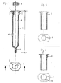
- Figure 4 shows a syringe plunger according to the invention in side view and immediately below the plunger end of a conventional injection syringe, partially in axial section.
- channels 2 or grooves are let into the plunger-side end of the syringe barrel 1, which are open both to the interior 4 of the syringe barrel 1 and to the filling opening .
- These channels or grooves run axially and extend a small distance towards the needle-side end of the syringe. They are approximately as long as the syringe plunger 3 is high, preferably they are a little shorter than the plunger 3 is high.
- the length of the channels or grooves 2 is based on the height of the so-called intermediate piston 3, that is the piston which, after filling the first component separates the first chamber from the second chamber slightly above the bypass 6.
- the syringe can have a customary needle attachment piece 5, for example a Luer cone, which can have a customary closure cap and / or can have a filter insert or attachment.
- the syringe can, for example, be loaded with a drug solution in a conventional filling device in which the syringe-side end hangs down and then provided with a conventional plunger 3.
- the piston 3 is only inserted into the syringe cylinder to such an extent that the ends of the channels 2 leading into the syringe are still exposed, ie are not covered by the piston.
- the lyophilized material introduced and the plunger 3 attached the syringe is transferred to the freeze-drying system. Freeze drying from the lyophilized material drawn vapors escape past the piston 3 via the channels 2.
- the plunger 3 is pushed into the syringe barrel until the channels 2 are closed.
- the channels 2 are somewhat shorter than the plunger 3 is high, this closure is already achieved in that the plunger 3 is pressed flush with the syringe end by the moving together of the setting plates of the freeze-drying system.
- the syringe can leave the freeze dryer in this state.
- the intermediate piston 3 is pushed further into the interior of the syringe until just above the point where the bypass 6 ends, then the second component, usually the solvent for the lyophilisate , filled, and the injection plunger inserted.
- ribs 8 can either rise above the inner cylinder wall 1, as shown in FIG. 2, or they can be flush with the inner wall of the cylinder, as shown in FIG. 3.
- the piston 3 is deformed when inserted by the projecting ribs 8, it does not lie completely against the rib side walls and there are air slots on both sides of each rib 8 parallel to the rib, which the interior 4 with the surrounding Connect space as long as the plunger 3 has not been fully inserted into the syringe end.
- the piston 3 must of course correspond in its outer diameter to at least the inner diameter of the syringe barrel without ribs.
- He can have a short approach of smaller diameter, with which it can be easily inserted into the syringe end and positioned and fixed between the ribs 8.
- the vapors can escape from the syringe during freeze drying through the annular gap between the outer wall of the short attachment and the inner wall of the syringe end.
- FIG. 3 is more advantageous, in which the ribs 8 represent a continuation of the cylinder inner wall 1 and the cylinder inner wall is expanded in the end region 9, so that when the piston 3 is inserted, an annular space 10 is created, through which the vapors from the interior during the freeze drying the syringe can escape.
- the number of channels 2 or fins 8 depends on their passage capacity and the amount of steam to be drawn off. It will generally be between 3 and 8, preferably 3 to 5.
- a piston can advantageously be used as the separating piston between the two chambers of a two-chamber syringe, the piston having oblique passages in its sealing lip facing the lyophilisate and an annular space (between the inner wall of the cylinder and the outer wall of the piston) of shallow depth between this and the subsequent sealing lip.
- Such a piston acts as a distributor for the solvent when the latter, when the syringe is actuated, enters the annular space in the region of the bypass and exits into the lyophilisate through the oblique passages.
- the syringe plunger 3 is provided with a cylindrical projection 11 of smaller diameter.
- the diameter of the approach is about 10 - 25% smaller than the diameter of the plunger in the area of a sealing bead and, of course, also smaller than the inside diameter of the syringe barrel.
- the plunger 3 is fixed with this approach 11 in the plunger end of the syringe barrel with the help of nub-like projections 12, by pushing the plunger only so far into the end of the syringe barrel that the nub-like projections grip the inner edge of the syringe barrel.
- the piston provided with such an attachment can have 1-3 sealing beads. If it is used in a two-chamber syringe, its sealing length must of course be somewhat shorter than the bypass in the syringe wall.
- the piston shown in Figure 4 also has axially extending groove-like depressions in the periphery of the shoulder 11 in order to improve the ventilation of the cylinder interior when the piston is attached. In this case too, of course, the plunger must not be pushed so far into the syringe end that the first sealing bead closes the annular gap or the ventilation channels 13.
- the syringe according to the invention offers significant advantages in lyophilization compared to the known lyophilizing syringes, which are open at the needle end and have to be closed there after the lyophilization by inserting a needle attachment piece, which requires laborious operations in the sterile field.
- a slight pushing of the piston 3 flush with the piston-side end of the syringe is sufficient to close the syringe after the freeze-drying has ended.
Landscapes
- Health & Medical Sciences (AREA)
- Vascular Medicine (AREA)
- Engineering & Computer Science (AREA)
- Anesthesiology (AREA)
- Biomedical Technology (AREA)
- Heart & Thoracic Surgery (AREA)
- Hematology (AREA)
- Life Sciences & Earth Sciences (AREA)
- Animal Behavior & Ethology (AREA)
- General Health & Medical Sciences (AREA)
- Public Health (AREA)
- Veterinary Medicine (AREA)
- Infusion, Injection, And Reservoir Apparatuses (AREA)
Priority Applications (1)
| Application Number | Priority Date | Filing Date | Title |
|---|---|---|---|
| AT88110812T ATE68708T1 (de) | 1987-07-21 | 1988-07-06 | Injektionsspritze fuer medizinische zwecke. |
Applications Claiming Priority (4)
| Application Number | Priority Date | Filing Date | Title |
|---|---|---|---|
| DE3724120 | 1987-07-21 | ||
| DE3724120 | 1987-07-21 | ||
| DE3816961 | 1988-05-18 | ||
| DE3816961A DE3816961A1 (de) | 1987-07-21 | 1988-05-18 | Injektionsspritze fuer medizinische zwecke |
Publications (3)
| Publication Number | Publication Date |
|---|---|
| EP0302248A1 true EP0302248A1 (fr) | 1989-02-08 |
| EP0302248B1 EP0302248B1 (fr) | 1991-10-23 |
| EP0302248B2 EP0302248B2 (fr) | 1996-01-10 |
Family
ID=25857794
Family Applications (1)
| Application Number | Title | Priority Date | Filing Date |
|---|---|---|---|
| EP88110812A Expired - Lifetime EP0302248B2 (fr) | 1987-07-21 | 1988-07-06 | Seringue à injection pour usage médical |
Country Status (4)
| Country | Link |
|---|---|
| US (1) | US4952208A (fr) |
| EP (1) | EP0302248B2 (fr) |
| AT (1) | ATE68708T1 (fr) |
| DE (2) | DE3816961A1 (fr) |
Cited By (14)
| Publication number | Priority date | Publication date | Assignee | Title |
|---|---|---|---|---|
| WO1992001485A1 (fr) * | 1990-07-20 | 1992-02-06 | Novo Nordisk A/S | Seringue a deux compartiments |
| WO1993021986A3 (fr) * | 1992-04-28 | 1994-01-06 | Schering Plough Healthcare | Applicateur de medicaments semi-solides |
| EP0599649A1 (fr) * | 1992-11-27 | 1994-06-01 | Daikyo Seiko, Ltd. | Récipient de seringne combiné |
| EP0664137A3 (fr) * | 1994-01-25 | 1995-08-30 | Becton Dickinson Co | |
| WO1996030066A1 (fr) * | 1995-03-29 | 1996-10-03 | Abbott Laboratories | Corps de seringue pour lyophilisation, reconstitution et administration |
| US5785682A (en) * | 1995-03-22 | 1998-07-28 | Abbott Laboratories | Pre-filled syringe drug delivery system |
| US5876372A (en) * | 1995-03-22 | 1999-03-02 | Abbott Laboratories | Syringe system accomodating seperate prefilled barrels for two constituents |
| EP1651114A1 (fr) * | 2003-08-07 | 2006-05-03 | FRASS, Michael | Appareil pour biopsie a l'aiguille |
| EP1911478A1 (fr) * | 2006-10-09 | 2008-04-16 | E-Z-EM, Inc. | Dispositif de seringue et système injecteur incluant une sortie pour dégager le vide dans la seringue |
| US8613730B2 (en) | 2008-11-26 | 2013-12-24 | Acist Medical Systems, Inc. | Apparatus and methods for fluid pressurizing units of injection systems |
| EP2739332A4 (fr) * | 2011-08-01 | 2015-04-01 | Synchrojet Llc | Obturateur/piston pour carpules d'ensemble seringue-carpule |
| WO2020169921A1 (fr) | 2019-02-21 | 2020-08-27 | Lyofal | Contenant pour le conditionnement de matières sous atmosphère contrôlée et procédé de conditionnement utilisant un tel contenant |
| US11033678B2 (en) | 2017-11-20 | 2021-06-15 | Agist Medical Systems, Inc. | Compact injector drive |
| US11040147B2 (en) | 2017-11-21 | 2021-06-22 | Acist Medical Systems, Inc. | Injector position sensing |
Families Citing this family (13)
| Publication number | Priority date | Publication date | Assignee | Title |
|---|---|---|---|---|
| US5135507A (en) * | 1990-05-10 | 1992-08-04 | Habley Medical Technology Corporation | One-piece syringe |
| US5350367A (en) * | 1990-11-06 | 1994-09-27 | Sterling Winthrop Inc. | Snap together hypodermic syringe holder |
| US5489266A (en) * | 1994-01-25 | 1996-02-06 | Becton, Dickinson And Company | Syringe assembly and method for lyophilizing and reconstituting injectable medication |
| DE4445969C1 (de) * | 1994-12-22 | 1996-03-14 | Schott Glaswerke | Spritzenzylinder für eine Zweikammer-Fertigspritze, Zweikammer-Fertigspritze und Verfahren zum Herstellen und Füllen derselben |
| US5685846A (en) * | 1995-02-27 | 1997-11-11 | Schott Parenta Systems, Inc. | Dual chamber internal by-pass syringe assembly |
| JPH11155951A (ja) * | 1997-12-01 | 1999-06-15 | Kaken Pharmaceut Co Ltd | 減圧シリンジおよびその製造方法 |
| US6907679B2 (en) * | 1998-11-12 | 2005-06-21 | Qlt Usa, Inc. | Method for lyophilizing an active agent |
| CN101394880A (zh) * | 2006-02-28 | 2009-03-25 | 久光制药株式会社 | 注射筒 |
| CN101678175A (zh) † | 2007-06-14 | 2010-03-24 | 塞诺菲-安万特德国有限公司 | 带有附件的双室卡普耳 |
| WO2011068544A1 (fr) * | 2009-12-04 | 2011-06-09 | Becton, Dickinson And Company | Cartouche pour contenir et distribuer un médicament |
| WO2013144901A2 (fr) * | 2012-03-30 | 2013-10-03 | Koninklijke Philips N.V. | Pointes de canule emboîtée |
| SG11201806437SA (en) | 2016-02-05 | 2018-08-30 | Tolmar Tharapeutics Inc | Vented cover plate for an array of syringes |
| USD908916S1 (en) | 2018-06-19 | 2021-01-26 | Tolmar Therapeutics, Inc. | Syringe restrictor plate |
Citations (6)
| Publication number | Priority date | Publication date | Assignee | Title |
|---|---|---|---|---|
| US3737973A (en) * | 1970-10-20 | 1973-06-12 | Becton Dickinson Co | Method and device for assembling a stopper to a syringe barrel |
| US4266557A (en) * | 1978-01-16 | 1981-05-12 | The Kendall Company | Low friction syringe |
| DE3339705A1 (de) | 1983-11-03 | 1985-05-15 | Arzneimittel Gmbh Apotheker Vetter & Co Ravensburg, 7980 Ravensburg | Spritze fuer medizinische zwecke |
| EP0144551A1 (fr) * | 1983-09-28 | 1985-06-19 | Becton Dickinson and Company | Assemblage de seringue pour médication à deux composants |
| EP0144483A2 (fr) | 1983-12-09 | 1985-06-19 | Arzneimittel GmbH Apotheker Vetter & Co. Ravensburg | Seringue pour applications médicales |
| EP0191122A1 (fr) | 1983-11-03 | 1986-08-20 | Arzneimittel GmbH Apotheker Vetter & Co. Ravensburg | Seringue pour applications médicales |
Family Cites Families (9)
| Publication number | Priority date | Publication date | Assignee | Title |
|---|---|---|---|---|
| US2591046A (en) * | 1948-10-18 | 1952-04-01 | Frederick M Turnbull | Hypodermic syringe assembly |
| US2717601A (en) * | 1949-08-10 | 1955-09-13 | Frederick M Turnbull | Syringe ampule |
| CH419458A (de) * | 1964-02-29 | 1966-08-31 | Hartmann Paul Ag | Injektionsspritze |
| US3255752A (en) * | 1965-01-28 | 1966-06-14 | Dick Peter | Hypodermic syringe |
| DK112893B (da) * | 1966-07-25 | 1969-01-27 | Bay Schmith N | Blandingssprøjte til brug ved blanding af forud fastsatte mængder af væsker og faste stoffer. |
| EP0072058A1 (fr) * | 1981-08-10 | 1983-02-16 | Duphar International Research B.V | Seringue à compartiments multiples |
| US4540410A (en) * | 1982-11-16 | 1985-09-10 | Serono Pharmaceutical Partners | Lyophilized compositions, preparation and use thereof |
| US4599082A (en) * | 1984-08-13 | 1986-07-08 | Becton, Dickinson And Company | Two-component syringe assembly |
| US4690154A (en) * | 1985-06-03 | 1987-09-01 | Timothy Woodford | Vented syringe |
-
1988
- 1988-05-18 DE DE3816961A patent/DE3816961A1/de not_active Withdrawn
- 1988-07-06 DE DE8888110812T patent/DE3865770D1/de not_active Expired - Fee Related
- 1988-07-06 EP EP88110812A patent/EP0302248B2/fr not_active Expired - Lifetime
- 1988-07-06 AT AT88110812T patent/ATE68708T1/de not_active IP Right Cessation
- 1988-07-22 US US07/227,185 patent/US4952208A/en not_active Expired - Fee Related
Patent Citations (6)
| Publication number | Priority date | Publication date | Assignee | Title |
|---|---|---|---|---|
| US3737973A (en) * | 1970-10-20 | 1973-06-12 | Becton Dickinson Co | Method and device for assembling a stopper to a syringe barrel |
| US4266557A (en) * | 1978-01-16 | 1981-05-12 | The Kendall Company | Low friction syringe |
| EP0144551A1 (fr) * | 1983-09-28 | 1985-06-19 | Becton Dickinson and Company | Assemblage de seringue pour médication à deux composants |
| DE3339705A1 (de) | 1983-11-03 | 1985-05-15 | Arzneimittel Gmbh Apotheker Vetter & Co Ravensburg, 7980 Ravensburg | Spritze fuer medizinische zwecke |
| EP0191122A1 (fr) | 1983-11-03 | 1986-08-20 | Arzneimittel GmbH Apotheker Vetter & Co. Ravensburg | Seringue pour applications médicales |
| EP0144483A2 (fr) | 1983-12-09 | 1985-06-19 | Arzneimittel GmbH Apotheker Vetter & Co. Ravensburg | Seringue pour applications médicales |
Cited By (25)
| Publication number | Priority date | Publication date | Assignee | Title |
|---|---|---|---|---|
| WO1992001485A1 (fr) * | 1990-07-20 | 1992-02-06 | Novo Nordisk A/S | Seringue a deux compartiments |
| WO1993021986A3 (fr) * | 1992-04-28 | 1994-01-06 | Schering Plough Healthcare | Applicateur de medicaments semi-solides |
| US5531703A (en) * | 1992-04-28 | 1996-07-02 | Schering-Plough Healthcare Products, Inc. | Applicator for semisolid medications |
| EP0599649A1 (fr) * | 1992-11-27 | 1994-06-01 | Daikyo Seiko, Ltd. | Récipient de seringne combiné |
| US5637100A (en) * | 1992-11-27 | 1997-06-10 | Daikyo Seiko, Ltd. | Syringe-cum-container |
| EP0664137A3 (fr) * | 1994-01-25 | 1995-08-30 | Becton Dickinson Co | |
| US5752940A (en) * | 1994-01-25 | 1998-05-19 | Becton Dickinson And Company | Syringe and method for lyophilizing and reconstituting injectable medication |
| US5785682A (en) * | 1995-03-22 | 1998-07-28 | Abbott Laboratories | Pre-filled syringe drug delivery system |
| US5876372A (en) * | 1995-03-22 | 1999-03-02 | Abbott Laboratories | Syringe system accomodating seperate prefilled barrels for two constituents |
| WO1996030066A1 (fr) * | 1995-03-29 | 1996-10-03 | Abbott Laboratories | Corps de seringue pour lyophilisation, reconstitution et administration |
| US5779668A (en) * | 1995-03-29 | 1998-07-14 | Abbott Laboratories | Syringe barrel for lyophilization, reconstitution and administration |
| EP1651114A1 (fr) * | 2003-08-07 | 2006-05-03 | FRASS, Michael | Appareil pour biopsie a l'aiguille |
| EP1911478A1 (fr) * | 2006-10-09 | 2008-04-16 | E-Z-EM, Inc. | Dispositif de seringue et système injecteur incluant une sortie pour dégager le vide dans la seringue |
| WO2008045876A3 (fr) * | 2006-10-09 | 2008-06-05 | E Z Em Inc | Dispositif de seringue et système d'injection comprenant une prise d'air destinée à réduire le vide à l'intérieur d'une seringue |
| CN101161303B (zh) * | 2006-10-09 | 2012-07-04 | 阿西斯特医疗系统公司 | 包括解除注射器中真空的通气口的注射器装置和注入器系统 |
| US8540683B2 (en) | 2006-10-09 | 2013-09-24 | Acist Medical Systems, Inc. | Syringe device and injector system including a vent for relieving a vacuum within a syringe |
| US8613730B2 (en) | 2008-11-26 | 2013-12-24 | Acist Medical Systems, Inc. | Apparatus and methods for fluid pressurizing units of injection systems |
| US9925338B2 (en) | 2008-11-26 | 2018-03-27 | Acist Medical Systems, Inc. | Apparatus and methods for fluid pressurizing units of injection systems |
| EP2739332A4 (fr) * | 2011-08-01 | 2015-04-01 | Synchrojet Llc | Obturateur/piston pour carpules d'ensemble seringue-carpule |
| US9022995B2 (en) | 2011-08-01 | 2015-05-05 | Synchrojet Llc | Stopper/plunger for carpules of syringe-carpule assembly |
| US11033678B2 (en) | 2017-11-20 | 2021-06-15 | Agist Medical Systems, Inc. | Compact injector drive |
| US11730885B2 (en) | 2017-11-20 | 2023-08-22 | Acist Medical Systems, Inc. | Compact injector drive |
| US11040147B2 (en) | 2017-11-21 | 2021-06-22 | Acist Medical Systems, Inc. | Injector position sensing |
| WO2020169921A1 (fr) | 2019-02-21 | 2020-08-27 | Lyofal | Contenant pour le conditionnement de matières sous atmosphère contrôlée et procédé de conditionnement utilisant un tel contenant |
| FR3093088A1 (fr) | 2019-02-21 | 2020-08-28 | Lyofal | Contenant pour le conditionnement de matières sous atmosphère contrôlée et procédé de conditionnement utilisant un tel contenant |
Also Published As
| Publication number | Publication date |
|---|---|
| DE3816961A1 (de) | 1989-02-02 |
| DE3865770D1 (de) | 1991-11-28 |
| ATE68708T1 (de) | 1991-11-15 |
| EP0302248B1 (fr) | 1991-10-23 |
| US4952208A (en) | 1990-08-28 |
| EP0302248B2 (fr) | 1996-01-10 |
Similar Documents
| Publication | Publication Date | Title |
|---|---|---|
| EP0302248B1 (fr) | Seringue à injection pour usage médical | |
| DE69508629T2 (de) | Spritze und Verfahren zur Lyophilisierung und Wiederherstellung von einspritzbaren Medikamenten | |
| DE69317650T2 (de) | Vorrichtung zur vorbereitung einer lösung, einer suspension oder einer emulsion einer medizinischen lösung | |
| DE69319495T2 (de) | Vorgefüllte Spritze | |
| DE69513696T2 (de) | Ein trockenes Medikament enthaltende und dessen Rekonstitution und Injektion ermöglichende Spritze | |
| EP0328699B1 (fr) | Seringue à usage médical | |
| DE69301448T2 (de) | Injektionsvorrichtung | |
| WO2007020239A1 (fr) | Contenant a deux chambres et procede pour le remplir | |
| DE69004949T2 (de) | Länglicher behälter mit zwei getrennten kammern auf der gleichen längsachse. | |
| EP0718002B1 (fr) | Seringue à deux compartiments et procédé de fabrication et de remplissage | |
| EP0399234B1 (fr) | Ampoule | |
| DE69725220T2 (de) | Kolbenvorrichtung mit Beipass zum Gebrauch im Zylinder einer Mehrkammerspritze | |
| EP0397977B1 (fr) | Seringue à usage médical | |
| EP0652019B1 (fr) | Seringue pour le mélange et l'administration de produits injectables | |
| WO2007020240A1 (fr) | Recipient a deux chambres pour la lyophilisation, et procede de remplissage et d'utilisation dudit recipient | |
| EP1038543B1 (fr) | Seringue pour buts médicaux | |
| DE60113410T2 (de) | Spritzensysteme für lyophilisierte arzneimittel und methode zu deren herstellung | |
| DE69605267T2 (de) | Vorrichtung zum Aufbewahren eines Mediums mit einem Stützring einer handbetätigten Pumpe zur Abgabe einzelner Dosen | |
| DE69007662T2 (de) | Verpackung zur Aufnahme und Mischung von zwei Komponenten. | |
| DE69620951T2 (de) | Vorgefüllte Spritze | |
| EP2680909A1 (fr) | Bouchon et procédé de fabrication dudit bouchon | |
| EP0922499A2 (fr) | Distributeur de fluides | |
| EP0412283A1 (fr) | Cylindre de seringue à usage médical | |
| DE8222348U1 (de) | Medizinische Spritze | |
| DE9400524U1 (de) | Vorrichtung zum Entleeren eines Schlauchbeutels |
Legal Events
| Date | Code | Title | Description |
|---|---|---|---|
| PUAI | Public reference made under article 153(3) epc to a published international application that has entered the european phase |
Free format text: ORIGINAL CODE: 0009012 |
|
| AK | Designated contracting states |
Kind code of ref document: A1 Designated state(s): AT BE CH DE ES FR GB GR IT LI LU NL SE |
|
| RBV | Designated contracting states (corrected) |
Designated state(s): AT BE CH DE FR GB IT LI NL |
|
| 17P | Request for examination filed |
Effective date: 19890622 |
|
| 17Q | First examination report despatched |
Effective date: 19901207 |
|
| GRAA | (expected) grant |
Free format text: ORIGINAL CODE: 0009210 |
|
| AK | Designated contracting states |
Kind code of ref document: B1 Designated state(s): AT BE CH DE FR GB IT LI NL |
|
| PG25 | Lapsed in a contracting state [announced via postgrant information from national office to epo] |
Ref country code: IT Free format text: LAPSE BECAUSE OF FAILURE TO SUBMIT A TRANSLATION OF THE DESCRIPTION OR TO PAY THE FEE WITHIN THE PRESCRIBED TIME-LIMIT;WARNING: LAPSES OF ITALIAN PATENTS WITH EFFECTIVE DATE BEFORE 2007 MAY HAVE OCCURRED AT ANY TIME BEFORE 2007. THE CORRECT EFFECTIVE DATE MAY BE DIFFERENT FROM THE ONE RECORDED. Effective date: 19911023 Ref country code: FR Effective date: 19911023 Ref country code: BE Effective date: 19911023 Ref country code: GB Effective date: 19911023 Ref country code: NL Effective date: 19911023 |
|
| REF | Corresponds to: |
Ref document number: 68708 Country of ref document: AT Date of ref document: 19911115 Kind code of ref document: T |
|
| REF | Corresponds to: |
Ref document number: 3865770 Country of ref document: DE Date of ref document: 19911128 |
|
| EN | Fr: translation not filed | ||
| NLV1 | Nl: lapsed or annulled due to failure to fulfill the requirements of art. 29p and 29m of the patents act | ||
| GBV | Gb: ep patent (uk) treated as always having been void in accordance with gb section 77(7)/1977 [no translation filed] | ||
| PLBI | Opposition filed |
Free format text: ORIGINAL CODE: 0009260 |
|
| 26 | Opposition filed |
Opponent name: ARZNEIMITTEL GMBH APOTHEKER VETTER & CO. Effective date: 19920718 |
|
| PUAH | Patent maintained in amended form |
Free format text: ORIGINAL CODE: 0009272 |
|
| STAA | Information on the status of an ep patent application or granted ep patent |
Free format text: STATUS: PATENT MAINTAINED AS AMENDED |
|
| 27A | Patent maintained in amended form |
Effective date: 19960110 |
|
| AK | Designated contracting states |
Kind code of ref document: B2 Designated state(s): AT BE CH DE FR GB IT LI NL |
|
| REG | Reference to a national code |
Ref country code: CH Ref legal event code: AEN Free format text: AUFRECHTERHALTUNG DES PATENTES IN GEAENDERTER FORM |
|
| EN | Fr: translation not filed | ||
| PGFP | Annual fee paid to national office [announced via postgrant information from national office to epo] |
Ref country code: CH Payment date: 19980708 Year of fee payment: 11 |
|
| PGFP | Annual fee paid to national office [announced via postgrant information from national office to epo] |
Ref country code: DE Payment date: 19980925 Year of fee payment: 11 |
|
| PG25 | Lapsed in a contracting state [announced via postgrant information from national office to epo] |
Ref country code: LI Free format text: LAPSE BECAUSE OF NON-PAYMENT OF DUE FEES Effective date: 19990731 Ref country code: CH Free format text: LAPSE BECAUSE OF NON-PAYMENT OF DUE FEES Effective date: 19990731 |
|
| PGFP | Annual fee paid to national office [announced via postgrant information from national office to epo] |
Ref country code: AT Payment date: 19990731 Year of fee payment: 12 |
|
| REG | Reference to a national code |
Ref country code: CH Ref legal event code: PL |
|
| PG25 | Lapsed in a contracting state [announced via postgrant information from national office to epo] |
Ref country code: DE Free format text: LAPSE BECAUSE OF NON-PAYMENT OF DUE FEES Effective date: 20000503 |
|
| PG25 | Lapsed in a contracting state [announced via postgrant information from national office to epo] |
Ref country code: AT Free format text: LAPSE BECAUSE OF NON-PAYMENT OF DUE FEES Effective date: 20000706 |