EP0303331A1 - Füllmaschine für festgesetzte Mengen von Flüssigkeiten - Google Patents
Füllmaschine für festgesetzte Mengen von Flüssigkeiten Download PDFInfo
- Publication number
- EP0303331A1 EP0303331A1 EP88201722A EP88201722A EP0303331A1 EP 0303331 A1 EP0303331 A1 EP 0303331A1 EP 88201722 A EP88201722 A EP 88201722A EP 88201722 A EP88201722 A EP 88201722A EP 0303331 A1 EP0303331 A1 EP 0303331A1
- Authority
- EP
- European Patent Office
- Prior art keywords
- damper
- rocker arm
- liquid
- vertical rod
- shaft
- Prior art date
- Legal status (The legal status is an assumption and is not a legal conclusion. Google has not performed a legal analysis and makes no representation as to the accuracy of the status listed.)
- Granted
Links
- 239000007788 liquid Substances 0.000 title claims abstract description 33
- 230000005540 biological transmission Effects 0.000 claims 1
- 230000000452 restraining effect Effects 0.000 claims 1
- 210000005069 ears Anatomy 0.000 description 3
- 230000006835 compression Effects 0.000 description 1
- 238000007906 compression Methods 0.000 description 1
- 230000001419 dependent effect Effects 0.000 description 1
- 239000000835 fiber Substances 0.000 description 1
- 230000009969 flowable effect Effects 0.000 description 1
- 238000004806 packaging method and process Methods 0.000 description 1
- 238000003756 stirring Methods 0.000 description 1
- 239000000126 substance Substances 0.000 description 1
Images




Classifications
-
- B—PERFORMING OPERATIONS; TRANSPORTING
- B67—OPENING, CLOSING OR CLEANING BOTTLES, JARS OR SIMILAR CONTAINERS; LIQUID HANDLING
- B67C—CLEANING, FILLING WITH LIQUIDS OR SEMILIQUIDS, OR EMPTYING, OF BOTTLES, JARS, CANS, CASKS, BARRELS, OR SIMILAR CONTAINERS, NOT OTHERWISE PROVIDED FOR; FUNNELS
- B67C3/00—Bottling liquids or semiliquids; Filling jars or cans with liquids or semiliquids using bottling or like apparatus; Filling casks or barrels with liquids or semiliquids
- B67C3/02—Bottling liquids or semiliquids; Filling jars or cans with liquids or semiliquids using bottling or like apparatus
- B67C3/22—Details
- B67C3/28—Flow-control devices, e.g. using valves
-
- B—PERFORMING OPERATIONS; TRANSPORTING
- B65—CONVEYING; PACKING; STORING; HANDLING THIN OR FILAMENTARY MATERIAL
- B65B—MACHINES, APPARATUS OR DEVICES FOR, OR METHODS OF, PACKAGING ARTICLES OR MATERIALS; UNPACKING
- B65B39/00—Nozzles, funnels or guides for introducing articles or materials into containers or wrappers
- B65B39/001—Nozzles, funnels or guides for introducing articles or materials into containers or wrappers with flow cut-off means, e.g. valves
- B65B39/002—Pivoting plates
Definitions
- the present invention relates to an apparatus for filling containers each with a specified amount of liquid such as flowable food.
- Examined Japanese Patent Publication No. 26550/1984 discloses such an apparatus which comprises a tubular nozzle body, a damper attached to the lower end of the nozzle body and movable upward and downward, a spring suspending member fixedly disposed in an upper portion of the nozzle body, a coiled spring suspended from the suspending member, a member connecting the lower end of the spring to the free end of the damper, and a resistance member fixed to the connecting member and positioned below the coiled spring for offering resistance to a liquid flowing down.
- the pressure of the liquid acting on the damper opens the damper against the force of the spring.
- the liquid pressure acting on the resistance member adds to the damper opening force, opening the damper to a greater extent and consequently permitting the nozzle body to discharge the liquid more rapidly.
- the rapid flow of the liquid precludes occurrence of air bubbles due to stirring of the liquid to assure a high-speed filling operation.
- the conventional apparatus has the following problem.
- the spring force if increased, makes the damper difficult to open, whereas a lower spring force renders the damper difficult to close. It is therefore difficult to adjust the spring force. Especially when the liquid to be filled contains a fibrous substance, fibers become lodged in the pivoted portion of the damper, making the damper no longer openable or closable smoothly.
- the main object of the present invention is to provide an apparatus for filling a specified amount of liquid into containers free of the above problem.
- the liquid filling apparatus of the present invention comprises a metering cylinder having a piston therein, a vertical filling nozzle having an open lower end and feedable with a liquid from the metering cylinder by the operation of the piston, a damper for opening and closing the open lower end of the filling nozzle, a spring biasing the damper to hold the nozzle end closed with the damper while the feed of the liquid is discontinued, and opening means adapted to open the damper against the spring simultaneously with or immediately before the start of feed of the liquid with the damper closed and to be subsequently brought out of operative relation with the damper before the feed of the liquid is discontinued so as to render the damper closable by the spring.
- the damper is forcibly opened by the opening means against the spring, and the force of the spring is set to such a magnitude that the damper can be closed properly.
- the damper can therefore be opend and closed with good stability.
- Fig. 1 shows a liquid filling apparatus which comprises a tank 11 for containing the liquid to be filled, a metering cylinder 14 connected to the bottom of the metering cylinder 11 by a connecting pipe 12 and having a piston 13 therein, a vertical tubular nozzle 15 connected to the metering cylinder 14, a damper 16 attached to the lower end of the filling nozzle 15 and pivotally movable upward and downward, a vertical rod 17 held by the filling nozzle 15 vertically movably, a member 18 connecting the free end of the damper 16 to the lower end of the vertical rod 17, and upper and lower coiled compression springs 19, 20 biasing the vertical rod 17 upward.
- the metering cylinder 14 has a T-shaped liquid conduit 21 having two open ends, one of which is provided with an inlet check valve 22 and the other with an outlet check valve 23.
- the filling nozzle 15 comprises an upper member 24, an intermediate member 25 and a lower member 26.
- the upper member 24 has a closure 27 covering its upper end and an inlet pipe portion 28 at the middle of its height. The pipe portion is connected to the metering cylinder 14.
- An upper guide member 29 is held between the upper member 24 and the intermediate member 25, and a lower guide member 30 between the intermediate member 25 and the lower member 26.
- the vertical rod 17 is guided upward and downward by these guide members 29 and 30.
- the entire upper and intermediate members 24, 25 and the upper portion of the lower member 26 are generally in the form of a hollow cylinder, but the lower portion of the lower member 26 is in the form of a tube with a square cross section. Of the four sides of the square of the open lower end, two opposed sides are provided with a pair of inverted trapezoidal dependent guide plates 31 opposed to each other.
- the damper 16 is in the form of a double-leafed hinged door and comprises a pair of opening plates 32 provided between the two guide plates 31.
- Each of the opening plates 32 comprises a rectangular bottom plate 33, and triangular side walls 34 extending upright from the respective side edges thereof and slidably in contact with the opposed inner surfaces of the guide plates 31.
- a horizontal pin 35 secured to the base end of the bottom wall 33 is supported at its opposite ends by the opening edge of the lower member 26.
- the vertical rod 17 is fixedly provided with upper and lower retainers 36, 37 above the upper and lower guide members 29, 30, respectively.
- Upper and lower springs 19, 20 are provided around the vertical rod 17 and disposed between the retainer 36 and the guide member 29, and between the retainer 37 and the guide member 30, respectively.
- the vertical rod 17 extends upward through the closure 27, with its upper end projecting beyond the closure.
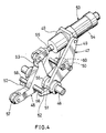
- a frame 41 and a horizontal drive shaft 42 supported thereon disposed at the right side of the upwardly projecting end of the vertical rod 17 .
- the drive shaft 42 fixedly carries a plate cam 43 and a pulley 44 having a belt 45 reeved therearound.
- the belt 45 is driven by the main shaft of a packaging machine including the filling apparatus.
- a horizontal support arm 46 is disposed between and slightly above the upper end of the vertical rod 17 and the drive shaft 42 and supported by the frame 41 so as to be parallel to the drive shaft 42.
- a cam follower 47 and a rocker arm 48 are pivotally movably supported by the shaft 46.
- the cam follower 47 has triangular webs 49 spaced apart from and opposed to each other.
- a horizontal roller pin 50 carrying a roller 60 thereon extends between and is secured to the webs 49 at their right lower corners.
- the roller 60 is in contact with the outer periphery of the plate cam 43.
- Each of the triangular webs 49 has at its left lower corner a boss 51 fitted around the horizontal support shaft 46 and formed with a leftwardly projecting ear 52.
- a hydraulic cylinder 53 has its body 54 attached to the remaining corner of each triangular web 49, with the piston rod 55 of the cylinder directed leftward.
- the rocker arm 48 has a boss 56 positioned between the two bosses 51 of the cam follower 47 and fitting around the support shaft 46 and extends leftward from the boss 56.
- the arm 48 carries at its left end a roller 57 in contact with the upper end face of the vertical rod 17.
- the rocker arm 48 has at a portion thereof close to its base portion horizontal rod-like stoppers 58 projecting from its opposite sides perpendicular thereto and bearing on the respective ears 52 from above.
- the rocker arm 48 is further formed with an upwardly projecting ear 59 having connected to its top end the piston rod 55 of the hydraulic cylinder 53.
- the time when the damper 16 is to be opened and the degree of opening thereof can be varied by altering the shape of the contour of the cam 43 for use with liquids of different properties.
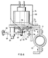
- a horizontal rotary shaft 61 is disposed at the right side of the upwardly projecting end of the vertical rod 17.
- the rotary shaft 61 is fixedly provided with a plate cam 62 approximately at its midportion and has a flange 63 at one end thereof.
- a horizontal support shaft 64 is disposed between and slightly above the upper end of the vertical rod 17 and the rotary shaft 61 so as to extend in parallel to the shaft 61.
- a rocker arm 65 is pivotally movably supported by the support shaft 64 and carries at its free end a roller 66 in bearing contact with the upper end of the vertical rod 17.
- a cam follower 67 is integral with the rocker arm 65.
- a pulse motor 68 has an output shaft 69 connected to the flange 63 of the rotary shaft 61 and is attached to a vertical support plate 72 supported by a bracket 71 on a post 70.
- the support plate 72 is formed with an aperture 73 having the output shaft 69 inserted therein.
- Covers 74 and 75 are attached to the respective sides of the support plate 72 for covering the pulse motor 68.
- the plate cam 62 has attached thereto a pointer 76 extending outward from the center of its rotation radially thereof.
- a proximity sensor 77 for detecting the pointer 76 is mounted on the support plate 72 by a bracket 78.
- the degree of opening of the damper 16 is easily adjustable, for example, according to the viscosity of the liquid to be filled. This renders the apparatus usable for liquids of different properties.
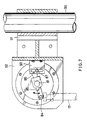
- a horizontal rotary shaft 81 is disposed at the right side of the upper end of the vertical rod 17, and a rocker arm 85 is secured at its base portion to the shaft 81.
- the rocker arm 85 carries at its forward end a roller 84 in contact with the upper end face of the vertical rod 17.
- the rotary shaft 81 is provided at its one end with a flange 81a connected to the output shaft 89 of a pulse motor 88.
- the pulse motor 88 is attached to a vertical support plate 92 supported by a bracket 91 on a post 90.
- the rocker arm 85 has attached thereto a sectorial plate 86 extending outward from the center of its rotation radially thereof.
- a proximity sensor 87 for detecting the plate 86 is attached to the support plate 92 by a bracket 93.
Landscapes
- Engineering & Computer Science (AREA)
- Mechanical Engineering (AREA)
- Basic Packing Technique (AREA)
Applications Claiming Priority (6)
| Application Number | Priority Date | Filing Date | Title |
|---|---|---|---|
| JP20225887A JPS6445203A (en) | 1987-08-13 | 1987-08-13 | Constant liquid feed apparatus |
| JP20226087A JPS6445205A (en) | 1987-08-13 | 1987-08-13 | Constant liquid feed apparatus |
| JP20225987A JPS6445204A (en) | 1987-08-13 | 1987-08-13 | Constant liquid feed apparatus |
| JP202259/87 | 1987-08-13 | ||
| JP202258/87 | 1987-08-13 | ||
| JP202260/87 | 1987-08-13 |
Publications (2)
| Publication Number | Publication Date |
|---|---|
| EP0303331A1 true EP0303331A1 (de) | 1989-02-15 |
| EP0303331B1 EP0303331B1 (de) | 1992-03-11 |
Family
ID=27328069
Family Applications (1)
| Application Number | Title | Priority Date | Filing Date |
|---|---|---|---|
| EP88201722A Expired EP0303331B1 (de) | 1987-08-13 | 1988-08-11 | Füllmaschine für festgesetzte Mengen von Flüssigkeiten |
Country Status (3)
| Country | Link |
|---|---|
| US (1) | US4982770A (de) |
| EP (1) | EP0303331B1 (de) |
| DE (1) | DE3869014D1 (de) |
Cited By (2)
| Publication number | Priority date | Publication date | Assignee | Title |
|---|---|---|---|---|
| EP0389065A1 (de) * | 1989-03-24 | 1990-09-26 | Shikoku Kakoki Co., Ltd. | Gerät zum Abfüllen einer bestimmten Flüssigkeitsmenge |
| CN115416885A (zh) * | 2022-09-26 | 2022-12-02 | 江西诺泰生物科技有限公司 | 一种果蔬固体饮料定量分装设备 |
Families Citing this family (2)
| Publication number | Priority date | Publication date | Assignee | Title |
|---|---|---|---|---|
| JPH09142403A (ja) * | 1995-11-22 | 1997-06-03 | Shikoku Kakoki Co Ltd | 液体定量充填装置 |
| FR2962413B1 (fr) * | 2010-07-08 | 2012-08-24 | Sidel Participations | Dispositif de remplissage avec systeme de regulation de debit |
Citations (6)
| Publication number | Priority date | Publication date | Assignee | Title |
|---|---|---|---|---|
| US1655584A (en) * | 1928-01-10 | Receptacle filling machine | ||
| US2243463A (en) * | 1937-08-14 | 1941-05-27 | Fmc Corp | Filling valve |
| US2645247A (en) * | 1947-12-31 | 1953-07-14 | Karl Kiefer Machine Company | Spout mechanism for filling machines |
| US3774655A (en) * | 1971-06-21 | 1973-11-27 | W Trusselle | Container-filling apparatus |
| DE2321206B1 (de) * | 1973-04-26 | 1974-05-09 | Siegfried 8900 Augsburg Ammann | Dosiervorrichtung zur Dosierung von flüssigen Füllgütern, insbesondere von Nahrungsmitteln |
| EP0138234A1 (de) * | 1983-08-19 | 1985-04-24 | Shikoku Kakoki Co., Ltd. | Vorrichtung zum Einfüllen einer bestimmten Flüssigkeitsmenge in Behälter |
Family Cites Families (13)
| Publication number | Priority date | Publication date | Assignee | Title |
|---|---|---|---|---|
| US621612A (en) * | 1899-03-21 | Flour-packer | ||
| US1106885A (en) * | 1914-04-22 | 1914-08-11 | Gustave Miller | Acetylene generating and storing apparatus. |
| US1201409A (en) * | 1915-06-02 | 1916-10-17 | Samuel A Whitsett | Acetylene-gas generator. |
| US1945065A (en) * | 1931-03-27 | 1934-01-30 | Shell Dev | Transportable apparatus for applying bitminous coverings, particularly to canal walls and the like inclined surfaces |
| US2103817A (en) * | 1935-03-04 | 1937-12-28 | Gerh Arehns Mek Verkst Ab | Apparatus for filling containers |
| US2482593A (en) * | 1944-09-25 | 1949-09-20 | F D Palmer Inc | Ice-cream package filling mechanism |
| US2597943A (en) * | 1945-10-19 | 1952-05-27 | George L N Meyer | Filler valve with automatic and emergency cutoff |
| US2723058A (en) * | 1951-04-13 | 1955-11-08 | Houdaille Hershey Of Indiana I | Snubber device for a weighing hopper in a fiber handling machine |
| US3072295A (en) * | 1958-10-27 | 1963-01-08 | Hubert O Teer Jr | Hopper gate apparatus and control |
| US3501030A (en) * | 1968-06-07 | 1970-03-17 | Braco Inc | Cam operating mechanism for unloading box |
| US3626997A (en) * | 1970-04-27 | 1971-12-14 | Reynolds Metals Co | Method of an apparatus for packaging a food product |
| US4230160A (en) * | 1978-12-11 | 1980-10-28 | National Instrument Company, Inc. | Adjustable suck-back device for sanitary pumps |
| US4925069A (en) * | 1987-09-17 | 1990-05-15 | Shikoku Kakoki Co., Ltd. | Apparatus for filling specified amount of liquid |
-
1988
- 1988-08-11 EP EP88201722A patent/EP0303331B1/de not_active Expired
- 1988-08-11 DE DE8888201722T patent/DE3869014D1/de not_active Expired - Fee Related
-
1990
- 1990-02-08 US US07/477,143 patent/US4982770A/en not_active Expired - Fee Related
Patent Citations (6)
| Publication number | Priority date | Publication date | Assignee | Title |
|---|---|---|---|---|
| US1655584A (en) * | 1928-01-10 | Receptacle filling machine | ||
| US2243463A (en) * | 1937-08-14 | 1941-05-27 | Fmc Corp | Filling valve |
| US2645247A (en) * | 1947-12-31 | 1953-07-14 | Karl Kiefer Machine Company | Spout mechanism for filling machines |
| US3774655A (en) * | 1971-06-21 | 1973-11-27 | W Trusselle | Container-filling apparatus |
| DE2321206B1 (de) * | 1973-04-26 | 1974-05-09 | Siegfried 8900 Augsburg Ammann | Dosiervorrichtung zur Dosierung von flüssigen Füllgütern, insbesondere von Nahrungsmitteln |
| EP0138234A1 (de) * | 1983-08-19 | 1985-04-24 | Shikoku Kakoki Co., Ltd. | Vorrichtung zum Einfüllen einer bestimmten Flüssigkeitsmenge in Behälter |
Cited By (3)
| Publication number | Priority date | Publication date | Assignee | Title |
|---|---|---|---|---|
| EP0389065A1 (de) * | 1989-03-24 | 1990-09-26 | Shikoku Kakoki Co., Ltd. | Gerät zum Abfüllen einer bestimmten Flüssigkeitsmenge |
| CN115416885A (zh) * | 2022-09-26 | 2022-12-02 | 江西诺泰生物科技有限公司 | 一种果蔬固体饮料定量分装设备 |
| CN115416885B (zh) * | 2022-09-26 | 2024-03-12 | 江西诺泰生物科技有限公司 | 一种果蔬固体饮料定量分装设备 |
Also Published As
| Publication number | Publication date |
|---|---|
| DE3869014D1 (de) | 1992-04-16 |
| EP0303331B1 (de) | 1992-03-11 |
| US4982770A (en) | 1991-01-08 |
Similar Documents
| Publication | Publication Date | Title |
|---|---|---|
| EP1425087B1 (de) | Vorrichtung und verfahren zum bewegen einer flüssigen suspension | |
| JP3742914B2 (ja) | カム装置 | |
| CA2606225C (en) | Fluid discharge nozzle | |
| US3924781A (en) | Dispenser apparatus suspended for bottom discharge | |
| CN209617625U (zh) | 一种吨袋包装机 | |
| US4504152A (en) | Mixing and/or kneading apparatus | |
| EP0303331A1 (de) | Füllmaschine für festgesetzte Mengen von Flüssigkeiten | |
| KR20190001868U (ko) | 승강형 노즐이 구비된 드럼용 액체 충진장치 | |
| US4724657A (en) | Apparatus for producing bag packages filled with liquid | |
| SU1355116A3 (ru) | Устройство дл подачи жидкости к упаковкам упаковочной машины | |
| CN113230947B (zh) | 一种消毒剂生产用定量控料装置 | |
| CN212313953U (zh) | 折勺合盖机构 | |
| CN216970088U (zh) | 一种高速液体物料包装机及其充填装置 | |
| CN112758877B (zh) | 一种接料装置及灌装机 | |
| CN113335621B (zh) | 一种袋装食品自动装填机构 | |
| CN215794590U (zh) | 称重式螺杆充填包装机 | |
| US4637200A (en) | Container forming apparatus for packaging machine | |
| CN214824286U (zh) | 一种半自动粉体包装机 | |
| CN208855900U (zh) | 一种空袋剔除机构 | |
| JPH0440246B2 (de) | ||
| CN109094834A (zh) | 一种空袋剔除机构 | |
| CN220875535U (zh) | 一种精准称重饲喂设备 | |
| CN222684270U (zh) | 一种全自动上称重灌装机 | |
| CN115285397A (zh) | 一种乳制品灌装用包装装置 | |
| EP0546498A1 (de) | Getränke-Aufbrühvorrichtung für Verkaufsautomat |
Legal Events
| Date | Code | Title | Description |
|---|---|---|---|
| PUAI | Public reference made under article 153(3) epc to a published international application that has entered the european phase |
Free format text: ORIGINAL CODE: 0009012 |
|
| AK | Designated contracting states |
Kind code of ref document: A1 Designated state(s): CH DE FR GB LI NL SE |
|
| 17P | Request for examination filed |
Effective date: 19890420 |
|
| 17Q | First examination report despatched |
Effective date: 19900731 |
|
| GRAA | (expected) grant |
Free format text: ORIGINAL CODE: 0009210 |
|
| AK | Designated contracting states |
Kind code of ref document: B1 Designated state(s): CH DE FR GB LI NL SE |
|
| REF | Corresponds to: |
Ref document number: 3869014 Country of ref document: DE Date of ref document: 19920416 |
|
| ET | Fr: translation filed | ||
| PLBE | No opposition filed within time limit |
Free format text: ORIGINAL CODE: 0009261 |
|
| STAA | Information on the status of an ep patent application or granted ep patent |
Free format text: STATUS: NO OPPOSITION FILED WITHIN TIME LIMIT |
|
| 26N | No opposition filed | ||
| EAL | Se: european patent in force in sweden |
Ref document number: 88201722.1 |
|
| PGFP | Annual fee paid to national office [announced via postgrant information from national office to epo] |
Ref country code: DE Payment date: 19980701 Year of fee payment: 11 |
|
| PGFP | Annual fee paid to national office [announced via postgrant information from national office to epo] |
Ref country code: GB Payment date: 19980727 Year of fee payment: 11 |
|
| PGFP | Annual fee paid to national office [announced via postgrant information from national office to epo] |
Ref country code: SE Payment date: 19980817 Year of fee payment: 11 |
|
| PGFP | Annual fee paid to national office [announced via postgrant information from national office to epo] |
Ref country code: FR Payment date: 19980826 Year of fee payment: 11 |
|
| PGFP | Annual fee paid to national office [announced via postgrant information from national office to epo] |
Ref country code: NL Payment date: 19980828 Year of fee payment: 11 |
|
| PGFP | Annual fee paid to national office [announced via postgrant information from national office to epo] |
Ref country code: CH Payment date: 19980831 Year of fee payment: 11 |
|
| PG25 | Lapsed in a contracting state [announced via postgrant information from national office to epo] |
Ref country code: GB Free format text: LAPSE BECAUSE OF NON-PAYMENT OF DUE FEES Effective date: 19990811 |
|
| PG25 | Lapsed in a contracting state [announced via postgrant information from national office to epo] |
Ref country code: SE Free format text: THE PATENT HAS BEEN ANNULLED BY A DECISION OF A NATIONAL AUTHORITY Effective date: 19990830 |
|
| PG25 | Lapsed in a contracting state [announced via postgrant information from national office to epo] |
Ref country code: LI Free format text: LAPSE BECAUSE OF NON-PAYMENT OF DUE FEES Effective date: 19990831 Ref country code: CH Free format text: LAPSE BECAUSE OF NON-PAYMENT OF DUE FEES Effective date: 19990831 |
|
| PG25 | Lapsed in a contracting state [announced via postgrant information from national office to epo] |
Ref country code: NL Free format text: LAPSE BECAUSE OF NON-PAYMENT OF DUE FEES Effective date: 20000301 |
|
| GBPC | Gb: european patent ceased through non-payment of renewal fee |
Effective date: 19990811 |
|
| REG | Reference to a national code |
Ref country code: CH Ref legal event code: PL |
|
| PG25 | Lapsed in a contracting state [announced via postgrant information from national office to epo] |
Ref country code: FR Free format text: LAPSE BECAUSE OF NON-PAYMENT OF DUE FEES Effective date: 20000428 |
|
| EUG | Se: european patent has lapsed |
Ref document number: 88201722.1 |
|
| NLV4 | Nl: lapsed or anulled due to non-payment of the annual fee |
Effective date: 20000301 |
|
| PG25 | Lapsed in a contracting state [announced via postgrant information from national office to epo] |
Ref country code: DE Free format text: LAPSE BECAUSE OF NON-PAYMENT OF DUE FEES Effective date: 20000601 |
|
| REG | Reference to a national code |
Ref country code: FR Ref legal event code: ST |