EP0303408A2 - Motorrad - Google Patents
Motorrad Download PDFInfo
- Publication number
- EP0303408A2 EP0303408A2 EP88307239A EP88307239A EP0303408A2 EP 0303408 A2 EP0303408 A2 EP 0303408A2 EP 88307239 A EP88307239 A EP 88307239A EP 88307239 A EP88307239 A EP 88307239A EP 0303408 A2 EP0303408 A2 EP 0303408A2
- Authority
- EP
- European Patent Office
- Prior art keywords
- receiving chamber
- motorcycle according
- engine
- frame
- chamber
- Prior art date
- Legal status (The legal status is an assumption and is not a legal conclusion. Google has not performed a legal analysis and makes no representation as to the accuracy of the status listed.)
- Granted
Links
Images








Classifications
-
- B—PERFORMING OPERATIONS; TRANSPORTING
- B62—LAND VEHICLES FOR TRAVELLING OTHERWISE THAN ON RAILS
- B62M—RIDER PROPULSION OF WHEELED VEHICLES OR SLEDGES; POWERED PROPULSION OF SLEDGES OR SINGLE-TRACK CYCLES; TRANSMISSIONS SPECIALLY ADAPTED FOR SUCH VEHICLES
- B62M7/00—Motorcycles characterised by position of motor or engine
- B62M7/02—Motorcycles characterised by position of motor or engine with engine between front and rear wheels
- B62M7/06—Motorcycles characterised by position of motor or engine with engine between front and rear wheels directly under the saddle or seat
-
- B—PERFORMING OPERATIONS; TRANSPORTING
- B62—LAND VEHICLES FOR TRAVELLING OTHERWISE THAN ON RAILS
- B62K—CYCLES; CYCLE FRAMES; CYCLE STEERING DEVICES; RIDER-OPERATED TERMINAL CONTROLS SPECIALLY ADAPTED FOR CYCLES; CYCLE AXLE SUSPENSIONS; CYCLE SIDE-CARS, FORECARS, OR THE LIKE
- B62K19/00—Cycle frames
- B62K19/46—Luggage carriers forming part of frame
Definitions
- This invention relates to a motorcycle provided with a receiving chamber having a relatively large capacity capable of receiving a large article, such as a helmet.
- Another problem encountered in such conventional prior art motorcycles is that, in the event that an attempt is made to increase the diameter of the rear wheel, steps taken to avoid interference between the receiving chamber and the rear wheel including moving the rear wheel shaft rearwardly, or raising the entire receiving chamber upwardly, or, alternatively, raising only the bottom of the receiving chamber.
- steps taken to avoid interference between the receiving chamber and the rear wheel including moving the rear wheel shaft rearwardly, or raising the entire receiving chamber upwardly, or, alternatively, raising only the bottom of the receiving chamber.
- the present invention seeks to ameliorate the above-described problems.
- the invention provides a motorcycle comprising a longitudinally extending frame; a front wheel and a rear wheel connecting with said frame at opposite ends thereof; an engine carried by said frame; a transmission extending generally horizontally and rearwardly from said engine to operatively connect said engine and said rear wheel; a box-like receiving chamber with an open upper end carried by said frame rearwardly of said engine and in overlying relation to said transmission in close proximity thereto; and a seat pivotally attached to said receiving chamber for opening and closing the upper end thereof.
- the motorcycle includes a forwardly inclined engine and a transmission case extending approximately horizontally rearwardly therefrom between the front wheel and the rear wheel.
- An upwardly open box-like receiving chamber is provided in close proximity to and above the transmission case, the engine being disposed forwardly of the receiving chamber.
- a seat covers the opening of the receiving chamber so that the opening may be opened and closed by pivoting the seat.
- a motorcycle having a helmet-receiving chamber below the seat is provided with a bottom plate of the receiving chamber extending obliquely rearwardly and upwardly with respect to an upward portion of the rear wheel.
- a recess for avoiding interference with the rear wheel is provided by the formation of a depression in the inclined portion of the bottom plate which depression extends into the interior of the receiving chamber as a protrusion.
- the described arrangement provides a support for positioning the lower opening of the helmet on the extended protrusion of the bottom plate.
- the lower opening of the helmet assumes a position with respect to the extended portion permitting the extended portion to extend inwardly of the helmet opening and, therefore, the helmet can be received without trouble.
- the invention therefore provides a motorcycle intended for a larger capacity of a receiving portion so that relatively large articles may be received therein.
- the preferred forms of motorcycle of the described type can provide for a rear wheel of increased diameter, without increasing the wheel base, or the height of the seat, or without constituting an obstacle to receiving a helmet into the receiving chamber.
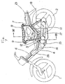
- Figure 1 to 4 show one embodiment of the present invention.
- This embodiment relates to a small motorcycle in which a body frame 3 is provided between a front wheel 1 and a rear wheel 2.
- the body frame 3 is composed of a single main frame 4 comprising a pipe having a relatively large diameter and a pair of rear frames 5 connected to the rear portion of the main frame and each comprising a pipe having a relatively small diameter.
- the body frame 3 is formed to be downwardly curved between the front wheel 1 and the rear wheel 2.
- the body frame 3 is covered with a body cover 6 made of synthetic resinous material.
- a seat 8 is mounted on the opening of the receiving chamber 7 so that one end thereof may be opened and closed by a hinge 9, also serving as a cover of the receiving chamber 7.
- the exterior of the receiving chamber 7 is enclosed by the body cover and is thereby hidden from sight.
- the upper end of the receiving chamber 7 defining the opening includes a seat receiving portion 7a that is foldedly offset and can support the bottom plate 8a of the seat.
- the reference numeral 8b designates a groove-like seal portion formed on the side of the seat 8 to receive the upper end of the body cover 6 thereby providing a waterproof construction.
- the receiving chamber 7 is made of synthetic resin and is in the form of a strong member for supporting the loads of the seat 8 and of an occupant. It has a large capacity capable of receiving a relatively large article, such as a full-face helmet H (see Figure 2).
- the bottom of the receiving chamber 7 has an approximately V-shape section whose front and rear walls rise obliquely toward the front and rear, respectively, of the vehicle.
- the exterior side of the rear wall 7b is provided with laterally spaced brackets 10 comprising a pair of holding elements. Each rear frame 5 is held between the holding elements of the brackets 10 and fastened by bolts 11.
- the rear wall, at 7b, provides an upwardly curved and protruding shape that permits the wall to serve as a rear fender for the rear wheel 2.
- the forward portion of the chamber bottom 7c is fastened by bolts 13 to a bracket 12 extending perpendicularly to the main frame 4 as shown in Figure 3.
- the reference numeral 14 designates a carburetor, 15 a crank case, 16 an engine, 17 a transmission case containing a transmission belt which is one example of the form of transmission contemplated by the present invention, and 18 a rear cushion unit.
- the engine 16 is suspended by a pivot link 15a from the main frame 4 in the state wherein the engine is forwardly disposed in a substantially horizontal attitude.
- the rear cushion unit 18 has its upper end mounted to one side portion of the rear frame 5 by a bolt 19 and its bottom end mounted by a bolt 21 to a substantially U-shaped bracket 20 that is mounted on the upper portion of the transmission case 17.
- the reference numeral 22 designates a V belt enclosed within the transmission case.
- the cusion unit 18 may, alternatively, be mounted at a lower position by supporting the lower end thereof by the lower portion of the transmission case. In this way, the rear frame 5 can be disposed more to a horizontal attitude, which is more advantageous when it is desired to have the volume of the receiving chamber 7 enlarged.
- FIG. 1 Other elements illustrated in Figure 1 include a fuel tank 23 mounted over the main frame 4, a lid 24 formed on the body cover 6, a battery 25 and an oil tank 26.
- the height of the seat from the ground can be made equal to, or less than, that of comparable prior art vehicles, and yet the receiving chamber 7 formed thereunder can be extended into close proximity to the transmission case 17.
- the interior of the chamber 7 can be formed with an extended depth to provide a capacity sufficiently great to enable reception of larger articles than that which could be received by the prior art.
- the main frame 4 is inclined rearwardly between the front wheel 1 and the rear wheel 2.
- the main frame 4 suspends and supports the engine 16 in a state frontwardly inclined slightly above the horizontal.
- a carburetor 14 connected to the engine 16 is connected to an air cleaner case 31 through a connecting tube 30.
- the air cleaner case 31 is interiorly provided with a filter element 32, over which is provided a diaphragm 33, as shown in Figure 6.
- the air cleaner case 31 is formed integral with the lower portion of the receiving chamber 7, and the diaphragm 33 forms the bottom thereof and, at the same time, supports the upper portion of the filter element 32.
- the reference numeral 34 designates bolts used to mount the diaphragm 33. It is possible to receive a relatively large full-face type helmet H in its normal vertical state or in an inverted vertical state in the described receiving chamber 7.
- a tandem seat 8 is mounted on the upper opening of the receiving chamber 7 so that the seat may be opened and closed by a hinge 9.
- oppositely spaced shoulders 35 are formed adjacent the connecting portion of the air cleaner case 31 thereby permitting the chamber to be supported on a pair of left and right reinforcing pipes 36 on the shoulders 35.
- the rear end of the reinforcing pipes 36 are connected to an intermediate portion of the rear frame which is formed to extend obliquely from the rear end of the main frame 4 toward the rear portion of the vehicle.
- a rear swing arm 37 is pivotably supported on the rear end of the main frame 4, and the intermediate portion of the rear frame 5 contains a bracket connecting the upper end while the rear swing arm 37 connects the lower end of the cushion unit 18.
- reference numeral 38 designates a sprocket
- 39 a drive chain which illustrates another example of the transmission contemplated for use with the present invention.
- the reference numeral 24 designates a relatively large fuel tank.
- the receiving chamber 7 according to the present embodiment is formed integral with the air cleaner case 31. Therefore, it is possible to reduce the number of parts to simplify the construction.
- FIGS 7 to 8 show still another embodiment of the invention.
- a battery case is formed integral with the receiving chamber 7 of the kind described in connection with the first embodiment shown in Figures 1 to 4. Accordingly, the description will be made using the same reference numerals for common parts.
- a battery case 40 is integrally projected further downwardly from a part of the bottom of the receiving chamber 7.
- the battery case 40 is open to the bottom of the chamber 7 and receives a battery 25.
- a detachable lid 41 is provided to close the opening between the chamber bottom and the battery case 40. Accordingly, for purpose of security the lid 40 can be operated only from the inside of the receiving chamber 7.
- the support portion for the battery 25 can be formed integral with the chamber 7, the construction is simplified. Additionally, by relocating the battery, the rear portion of the seat 8 can be extended into the space previously occupied by the battery. Also, the size of the fuel tank 26 can be increased and an oil tank 23 can now be mounted over the main frame 4.
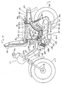
- Figure 9 illustrates another embodiment of a motorcycle according to the present invention.
- the body frame 102 is composed of a main frame 103 formed from a round pipe having a relatively large diameter section and a rear frame 104 formed of a rectangular pipe having a laterally extending section.
- the main frame 103 is inclined so as to be gradually lowered from the front end 103a toward the rear end 103b.
- the rear frame 104 is curved in order to avoid interference with the rear wheel 128 which will be described hereinafter.
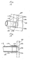
- the rear end 103b of the main frame 103 is fitted into holes 105a and 105b bored in front and rear walls 104a and 104b at the lower end of the rear frame 104, as shown in Figures 12 and 13 and fixed by welding, or the like.
- a front wheel 107 is supported on the front end 103a of the main frame 103 through a front fork 106, the front wheel 107 being steered by a handle 108.
- a fuel tank-receiving frame 110 is mounted on a bracket 109 provided at the rear end of the rear frame 104, and a fuel tank 116 is provided within the frame 110.
- a helmet-receiving chamber 111 Upwardly from the rear portion, of an approximately intermediate portion of the body frame 102, is provided a helmet-receiving chamber 111, the upper surface of which is open as shown in Figures 9, 12 and 15.
- This receiving chamber 111 has its bottom plate extended from a forward to upward portion of the rear wheel 128, the bottom plate comprising a front bottom plate portion 111b and a rear bottom plate portion 111c.
- the front bottom plate portion 111b is positioned forwardly of the rear wheel 128 and secured by bolts 114a and nuts 114b to brackets 113 on both sides of the main frame 103 through rubber mounts 112 with a collar 112a fitted therein.
- the rear bottom plate portion 111c is inclined upwardly of the rear wheel 128 and has a rear wall 111d at the upper portion thereof. Upwardly of the front bottom plate portion 111b the front wall 111a is integrally continuously formed.
- a mount wall 115 projecting from the rear of the upper end thereof is secured by means of bolts 117 and nuts 118 to the upper surface of the bracket 109 on the upper end of the rear frame 104 through a rubber mount with a collar 116a fitted therein.
- a recess 119 for avoiding interference with the rear wheel 128 is projected into the interior of the chamber 111.
- the longitudinal shape of the recess 119 corresponds essentially to the rear frame 104.
- a projection 120 is provided inwardly of the rear bottom plate portion 111c of the chamber 111 corresponding substantially to the recess 119.
- This projection 120 has a shape corresponding to the shape of the peripheral edge of the lower opening 121a of a full-face type helmet 121 placed into the receiving chamber 111. As shown in Figure 14, the shape of the projection 120 is set somewhat smaller than the shape of the peripheral edge.
- the front bottom plate portion 111b of the receiving chamber 111 is provided with a support surface 160 by which the lower opening 121a of the helmet 121 is caused to be positioned toward the projection 120.
- This support surface 160 is formed by curving the front bottom plate portion 111b of the receiving chamber 111 into a shape corresponding to the rear curved surface 121b of the helmet 121.
- the support surface 160 is constructed by forming the bottom plate into the curved surface 121b, it is to be noted that, as shown in Figure 19, the front bottom plate portion 111b can be caused to extend horizontally and a separate support member 160a provided between it and the rear curved surface 121b of the helmet 121 to thereby constitute the support surface 160.
- a rear fender made of steel plate to strengthen the rear frame 104.
- a seat 123 is provided that also serves as a lid to open and close the opening to the chamber 111.
- the seat 123 is pivotably mounted by a hinge mechanism 124.
- An engine 125 is disposed downwardly of the body frame 102.
- the engine 125 has its crank case 126 integrally provided on the front end of the power transmission case 127.
- the rear wheel 128 is mounted on one side of the rear end of the power transmission case 127.
- Brackets 129 on both sides of the upper surface of the crank case 126 at the front end of the transmission case are mounted by bolts 131 and nuts 132 on a reinforcing plate 130 provided along a connection corner between the main frame 103 and the rear frame 104, thereby mounting the power transmission case 127 to the body frame.
- the rear wheel 128 is mounted in the central portion of the rear end of the power transmission case 127.
- a rear cushion 134 is interposed between the upper side of the rear end of the power transmission case 127 and the lower portion at the side of the bracket 109 on the upper end of the rear frame 104.
- the power transmission case 127 also serves as a cantilever rear fork since the rear end thereof swings up and down about the bolt 131.
- the turning force of the crank shaft (not shown) of the engine 125 is transmitted to the rear wheel 128 through a stepless speed change gear (not shown) whereby the rear wheel is rotatably driven.
- a space 136 is defined between the front side of the rear wheel 128 and the crank case 126, and an air cleaner 137 is disposed within the space 136.
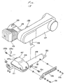
- the air cleaner 137 comprises, as shown in Figure 17, a case 138, a filter element 139 received within the case, a cover 142 secured by a screw 141 to the open surface of the case through a seal 140, a duct 143 connected to an air inlet 142a of the cover, and a connecting tube 144, one end of which is connected to an air outlet 138a from the case.
- the air cleaner 137 has a bracket 138b at the lower end of the case 138 secured to one side of the power transmission case 127 by means of a screw 145.
- the other end of the connecting tube 144 is connected to the intake port 125a of the engine 125 through the carburetor 146.
- the cover 142 may be removed in the direction of arrow A in Figure 16.
- a muffler 147 is disposed downwardly of the power transmission case 127. As shown in Figure 18, this muffler 147 is composed of a first silencer chamber 148 in the form of a square box, a second cylindrical silencer chamber 149, the front end of which is connected to one side from a lateral intermediate portion of the rear side of said first silencer chamber 148, and a small diameter tail pipe 150 projecting from the rear end of the second silencer chamber 149.
- a connection pipe 151 extends from the front side of the first silencer chamber 148 and is connected to an exhaust port 125b from the engine 125.
- the muffler 147 has a bracket 152 which projects downwardly from the second silencer chamber 149 is mounted by means of a screw 154 on a bracket 153 that projects downwardly from the power transmission case 127.
- the reference numeral 155 designates an ornamental member for improving the external appearance of the muffler 127. Both ends of the member 155 are mounted by means of screws 156 to the outer surface of the muffler 147.
- the body frame 102, the receiving chamber 111 and the fuel tank receiving frame 110 are covered with a body cover 157 made of synthetic resin.
- a battery case 158 is mounted to the lower side of the main frame 103.
- the air cleaner 137 is positioned forwardly of the rear wheel 128 and disposed within the space 136 defined by the power transmission case 127, detachment of the cover 142 for maintenance of the air cleaner 137 can be effected on the opposite side of the power transmission case 127, thus improving workability.
- the rear frame 4 is constructed of a hollow member of rectangular section whose lateral width is greater than its depth, the frame can produce a section modulus and, thereby, a structural stiffness equal to that produced by a hollow circular pipe of greater diameter. Consequently, greater clearance space between the rear wheel 28 and the rear frame 4 is made available by the described arrangement.
- the silencer chambers 148 and 149 of the muffler 147 are disposed below the power transmission case 127 from the lower portion of the crank case 126 of the engine 125 to one side of the rear wheel 128, the volume of the muffler 147 can be increased without lowering the height of the muffler from the ground, and when the rear wheel 128 is mounted or removed, the muffler 147 need not be removed.
- the receiving chamber provided under the seat is designed to fit into the space formed by the forwardly inclined engine disposed in front of the chamber and the transmission disposed substantially horizontally and extending rearwardly therefrom. Therefore, the receiving chamber can be increased in capacity while the height of the seat can be equal to, or lower than the prior art.
- a beneficial effect of the embodiment is that the diameter of the rear wheel can be increased without increasing the length of the wheel base, or the height of the seat, or without constituting an obstacle to receiving the helmet into the receiving chamber.
Landscapes
- Engineering & Computer Science (AREA)
- Mechanical Engineering (AREA)
- Chemical & Material Sciences (AREA)
- Combustion & Propulsion (AREA)
- Transportation (AREA)
- Automatic Cycles, And Cycles In General (AREA)
Applications Claiming Priority (2)
| Application Number | Priority Date | Filing Date | Title |
|---|---|---|---|
| JP62198724A JPH0790814B2 (ja) | 1987-08-08 | 1987-08-08 | 自動2輪車 |
| JP198724/87 | 1987-08-08 |
Publications (3)
| Publication Number | Publication Date |
|---|---|
| EP0303408A2 true EP0303408A2 (de) | 1989-02-15 |
| EP0303408A3 EP0303408A3 (en) | 1990-06-13 |
| EP0303408B1 EP0303408B1 (de) | 1994-07-27 |
Family
ID=16395937
Family Applications (1)
| Application Number | Title | Priority Date | Filing Date |
|---|---|---|---|
| EP88307239A Expired - Lifetime EP0303408B1 (de) | 1987-08-08 | 1988-08-05 | Motorrad |
Country Status (4)
| Country | Link |
|---|---|
| US (1) | US4901813A (de) |
| EP (1) | EP0303408B1 (de) |
| JP (1) | JPH0790814B2 (de) |
| ES (1) | ES2056933T3 (de) |
Cited By (11)
| Publication number | Priority date | Publication date | Assignee | Title |
|---|---|---|---|---|
| FR2642390A1 (fr) * | 1989-02-02 | 1990-08-03 | Honda Motor Co Ltd | Motocyclette a groupe de propulsion de type monobloc oscillant |
| US5020625A (en) * | 1988-09-06 | 1991-06-04 | Suzuki Jidosha Kogyo Kabushiki Kaisha | Motor bicycle provided with article accommodating apparatus |
| EP0581310A1 (de) * | 1992-07-31 | 1994-02-02 | Yamaha Hatsudoki Kabushiki Kaisha | Gepäckbehälter für Motorrad |
| EP0726197A1 (de) * | 1995-02-07 | 1996-08-14 | Honda Giken Kogyo Kabushiki Kaisha | Schwingarmstrukturfür Fahrzeugaufhängung |
| EP0737615A3 (de) * | 1995-04-11 | 1997-07-16 | Honda Motor Co Ltd | Schwingarmstruktur für Fahrzeugaufhängung |
| EP1695899A1 (de) * | 2005-02-24 | 2006-08-30 | Kwang Yang Motor Co., Ltd. | Motorradbehälter zur Aufbewahrung von Gegenständen |
| EP1818249A1 (de) * | 2006-01-31 | 2007-08-15 | HONDA MOTOR CO., Ltd. | Hinterdämpferanordnung für ein Motorrad |
| EP1961648A3 (de) * | 2007-02-21 | 2008-11-05 | HONDA MOTOR CO., Ltd. | Aufbewahrungsbox in einem Motorrad und Verfahren zum Montieren der Aufbewahrungsbox |
| EP2130751A4 (de) * | 2007-03-30 | 2010-12-01 | Yamaha Motor Co Ltd | Grätschsitzfahrzeug |
| EP2128006A4 (de) * | 2007-02-22 | 2010-12-01 | Yamaha Motor Co Ltd | Grätschsitzfahrzeug |
| EP2546129A1 (de) * | 2011-07-11 | 2013-01-16 | Yamaha Hatsudoki Kabushiki Kaisha | Zweirädriges Kraftfahrzeug |
Families Citing this family (23)
| Publication number | Priority date | Publication date | Assignee | Title |
|---|---|---|---|---|
| GB2184990B (en) * | 1985-12-27 | 1988-12-29 | Honda Motor Co Ltd | Scooter type vehicle |
| JP2868787B2 (ja) * | 1989-06-13 | 1999-03-10 | ヤマハ発動機株式会社 | 自動二輪車における車両構成部品配設構造 |
| JPH03128789A (ja) * | 1989-07-13 | 1991-05-31 | Honda Motor Co Ltd | 電動式車両 |
| US5222572A (en) * | 1989-07-13 | 1993-06-29 | Honda Giken Kogyo Kabushiki Kaisha | Electric motor driven vehicle and power unit thereof |
| JP4364361B2 (ja) * | 1999-09-05 | 2009-11-18 | 本田技研工業株式会社 | 自動2輪車 |
| JP4058884B2 (ja) * | 2000-05-23 | 2008-03-12 | スズキ株式会社 | 自動二輪車の後輪懸架装置 |
| JP3867486B2 (ja) * | 2000-09-06 | 2007-01-10 | スズキ株式会社 | 自動二輪車 |
| JP2004114870A (ja) * | 2002-09-26 | 2004-04-15 | Honda Motor Co Ltd | 低床式車両のリヤクッション取付構造 |
| US7137637B2 (en) * | 2002-11-15 | 2006-11-21 | Ackley Erick J | Wheel fender with integral tank |
| US7093856B2 (en) | 2003-03-13 | 2006-08-22 | Flexahopper Plastics Ltd. | Truck tank for accommodating a bed-mounted hitch |
| US7363999B2 (en) * | 2004-02-10 | 2008-04-29 | Bush Hog, Llc | Positive air flow drive train unit for utility vehicle |
| US7398562B2 (en) * | 2004-03-10 | 2008-07-15 | Easy Rhino Designs, Inc. | Article with 3-dimensional secondary element |
| WO2006005184A1 (en) * | 2004-07-14 | 2006-01-19 | Sport Maska Inc. | Adjustable helmet shell |
| TWI251568B (en) * | 2004-07-30 | 2006-03-21 | Kwang Yang Motor Co | Structure of storage box for all-terrain vehicle |
| CN100484819C (zh) * | 2004-08-10 | 2009-05-06 | 光阳工业股份有限公司 | 摩托车的置物箱装置 |
| ITTO20050666A1 (it) * | 2004-09-29 | 2006-03-30 | Honda Motor Co Ltd | Motociclo |
| JP2006103399A (ja) * | 2004-10-01 | 2006-04-20 | Yamaha Motor Co Ltd | 自動二輪車 |
| JP4767603B2 (ja) * | 2005-07-04 | 2011-09-07 | ヤマハ発動機株式会社 | パワーユニット及び該パワーユニットを備えた鞍乗型車両 |
| JP2008001278A (ja) * | 2006-06-23 | 2008-01-10 | Yamaha Motor Co Ltd | 鞍乗型車両 |
| JP4778919B2 (ja) * | 2007-02-21 | 2011-09-21 | 本田技研工業株式会社 | 自動二輪車 |
| JP4864121B2 (ja) * | 2009-07-09 | 2012-02-01 | ヤマハ発動機株式会社 | スクータ型車両 |
| JP2011031818A (ja) | 2009-08-04 | 2011-02-17 | Yamaha Motor Co Ltd | 自動二輪車 |
| US20190185091A1 (en) * | 2017-12-15 | 2019-06-20 | Dejan Mitrovic | Multifunctional motorcycle passenger seat system |
Family Cites Families (9)
| Publication number | Priority date | Publication date | Assignee | Title |
|---|---|---|---|---|
| GB830467A (en) * | 1955-06-13 | 1960-03-16 | Harry Holt | Improvements relating to motor-cycles |
| GB1537233A (en) * | 1975-12-17 | 1978-12-29 | Bothwell P | Two-wheeled vehicles |
| JPS5926089A (ja) * | 1982-08-04 | 1984-02-10 | Seiko Epson Corp | 電子時計 |
| JPS5926089U (ja) * | 1982-08-11 | 1984-02-17 | 本田技研工業株式会社 | 自動二輪車 |
| JPS6181884A (ja) * | 1984-09-18 | 1986-04-25 | 本田技研工業株式会社 | スク−タ−型小型車輌 |
| JPH0624012B2 (ja) * | 1985-07-05 | 1994-03-30 | 株式会社日立製作所 | ラベリング・プロセツサ |
| JPH07102828B2 (ja) * | 1985-08-06 | 1995-11-08 | ヤマハ発動機株式会社 | 自動二輪車の物入れ装置 |
| JPH0674068B2 (ja) * | 1985-10-01 | 1994-09-21 | ヤマハ発動機株式会社 | スク−タ型車輌の物入れ装置 |
| GB2184990B (en) * | 1985-12-27 | 1988-12-29 | Honda Motor Co Ltd | Scooter type vehicle |
-
1987
- 1987-08-08 JP JP62198724A patent/JPH0790814B2/ja not_active Expired - Fee Related
-
1988
- 1988-07-29 US US07/225,766 patent/US4901813A/en not_active Expired - Fee Related
- 1988-08-05 EP EP88307239A patent/EP0303408B1/de not_active Expired - Lifetime
- 1988-08-05 ES ES88307239T patent/ES2056933T3/es not_active Expired - Lifetime
Cited By (16)
| Publication number | Priority date | Publication date | Assignee | Title |
|---|---|---|---|---|
| US5020625A (en) * | 1988-09-06 | 1991-06-04 | Suzuki Jidosha Kogyo Kabushiki Kaisha | Motor bicycle provided with article accommodating apparatus |
| FR2642390A1 (fr) * | 1989-02-02 | 1990-08-03 | Honda Motor Co Ltd | Motocyclette a groupe de propulsion de type monobloc oscillant |
| BE1003347A5 (fr) * | 1989-02-02 | 1992-03-03 | Honda Motor Co Ltd | Motocyclette a groupe de propulsion de type monobloc oscillant. |
| EP0581310A1 (de) * | 1992-07-31 | 1994-02-02 | Yamaha Hatsudoki Kabushiki Kaisha | Gepäckbehälter für Motorrad |
| CN1051288C (zh) * | 1992-07-31 | 2000-04-12 | 雅马哈发动机株式会社 | 摩托车的贮藏箱 |
| EP0726197A1 (de) * | 1995-02-07 | 1996-08-14 | Honda Giken Kogyo Kabushiki Kaisha | Schwingarmstrukturfür Fahrzeugaufhängung |
| EP0737615A3 (de) * | 1995-04-11 | 1997-07-16 | Honda Motor Co Ltd | Schwingarmstruktur für Fahrzeugaufhängung |
| CN1071229C (zh) * | 1995-04-11 | 2001-09-19 | 本田技研工业株式会社 | 摆动装置式车辆中的摇臂结构 |
| EP1695899A1 (de) * | 2005-02-24 | 2006-08-30 | Kwang Yang Motor Co., Ltd. | Motorradbehälter zur Aufbewahrung von Gegenständen |
| EP1818249A1 (de) * | 2006-01-31 | 2007-08-15 | HONDA MOTOR CO., Ltd. | Hinterdämpferanordnung für ein Motorrad |
| US7588111B2 (en) | 2006-01-31 | 2009-09-15 | Honda Motor Co., Ltd. | Rear shock absorber arrangement structure for motorcycle |
| EP1961648A3 (de) * | 2007-02-21 | 2008-11-05 | HONDA MOTOR CO., Ltd. | Aufbewahrungsbox in einem Motorrad und Verfahren zum Montieren der Aufbewahrungsbox |
| US7794002B2 (en) | 2007-02-21 | 2010-09-14 | Honda Motor Co., Ltd. | Storage box structure in motorcycle and method of mounting storage box |
| EP2128006A4 (de) * | 2007-02-22 | 2010-12-01 | Yamaha Motor Co Ltd | Grätschsitzfahrzeug |
| EP2130751A4 (de) * | 2007-03-30 | 2010-12-01 | Yamaha Motor Co Ltd | Grätschsitzfahrzeug |
| EP2546129A1 (de) * | 2011-07-11 | 2013-01-16 | Yamaha Hatsudoki Kabushiki Kaisha | Zweirädriges Kraftfahrzeug |
Also Published As
| Publication number | Publication date |
|---|---|
| ES2056933T3 (es) | 1994-10-16 |
| JPH0790814B2 (ja) | 1995-10-04 |
| EP0303408A3 (en) | 1990-06-13 |
| EP0303408B1 (de) | 1994-07-27 |
| JPS6441485A (en) | 1989-02-13 |
| US4901813A (en) | 1990-02-20 |
Similar Documents
| Publication | Publication Date | Title |
|---|---|---|
| EP0303408B1 (de) | Motorrad | |
| CA1275939C (en) | Trunk structure in scooter-type vehicles | |
| US6073719A (en) | Body structure of a low floor motorcycle | |
| US5107952A (en) | Saddle type off-road vehicle | |
| US5076387A (en) | Saddle type vehicle having a storage receptacle | |
| US5048634A (en) | Motor bicycle | |
| EP1138932B1 (de) | Befestigung eines Luftfilters in einem Motorrad | |
| JP3836225B2 (ja) | 鞍乗り型車両のフレーム構造 | |
| US5060748A (en) | Saddle type vehicle having a storage receptacle | |
| JP3279017B2 (ja) | スクータ型車両 | |
| JPH0826163A (ja) | 自動二輪車の後部車体構造 | |
| JP3569597B2 (ja) | スクータ型車両における車体構造 | |
| AU615214B2 (en) | Motor scooter | |
| JPH0288376A (ja) | 自動2輪車のへルメット収納装置 | |
| JP2006315657A (ja) | 自動二輪車のマフラとブレーキペダルの配置構造 | |
| JP3795199B2 (ja) | 低床式自動二輪車 | |
| JP3617282B2 (ja) | 自動二輪車のツールボックス | |
| JPH05238462A (ja) | 自動二輪車の車体構造 | |
| JP2916495B2 (ja) | 鞍乗型車両 | |
| JPH03136987A (ja) | 自動2輪車のフレーム | |
| JPH01172083A (ja) | 鞍乗型車両 | |
| JP2002187586A (ja) | 車両用バッテリボックス取付構造 | |
| JP2862917B2 (ja) | 二・三輪車の後部トランク構造 | |
| JP2850241B2 (ja) | 自動2輪車 | |
| JPH07156851A (ja) | スクータ型車両 |
Legal Events
| Date | Code | Title | Description |
|---|---|---|---|
| PUAI | Public reference made under article 153(3) epc to a published international application that has entered the european phase |
Free format text: ORIGINAL CODE: 0009012 |
|
| AK | Designated contracting states |
Kind code of ref document: A2 Designated state(s): BE ES FR GB IT |
|
| PUAL | Search report despatched |
Free format text: ORIGINAL CODE: 0009013 |
|
| AK | Designated contracting states |
Kind code of ref document: A3 Designated state(s): BE ES FR GB IT |
|
| 17P | Request for examination filed |
Effective date: 19900924 |
|
| 17Q | First examination report despatched |
Effective date: 19911023 |
|
| ITTA | It: last paid annual fee | ||
| GRAA | (expected) grant |
Free format text: ORIGINAL CODE: 0009210 |
|
| AK | Designated contracting states |
Kind code of ref document: B1 Designated state(s): BE ES FR GB IT |
|
| ET | Fr: translation filed | ||
| REG | Reference to a national code |
Ref country code: ES Ref legal event code: FG2A Ref document number: 2056933 Country of ref document: ES Kind code of ref document: T3 |
|
| ITF | It: translation for a ep patent filed | ||
| PLBE | No opposition filed within time limit |
Free format text: ORIGINAL CODE: 0009261 |
|
| STAA | Information on the status of an ep patent application or granted ep patent |
Free format text: STATUS: NO OPPOSITION FILED WITHIN TIME LIMIT |
|
| 26N | No opposition filed | ||
| PGFP | Annual fee paid to national office [announced via postgrant information from national office to epo] |
Ref country code: GB Payment date: 19960710 Year of fee payment: 9 |
|
| PGFP | Annual fee paid to national office [announced via postgrant information from national office to epo] |
Ref country code: BE Payment date: 19960910 Year of fee payment: 9 |
|
| PG25 | Lapsed in a contracting state [announced via postgrant information from national office to epo] |
Ref country code: GB Free format text: LAPSE BECAUSE OF NON-PAYMENT OF DUE FEES Effective date: 19970805 |
|
| PG25 | Lapsed in a contracting state [announced via postgrant information from national office to epo] |
Ref country code: BE Free format text: LAPSE BECAUSE OF NON-PAYMENT OF DUE FEES Effective date: 19970831 |
|
| BERE | Be: lapsed |
Owner name: HONDA GIKEN KOGYO K.K. Effective date: 19970831 |
|
| GBPC | Gb: european patent ceased through non-payment of renewal fee |
Effective date: 19970805 |
|
| PGFP | Annual fee paid to national office [announced via postgrant information from national office to epo] |
Ref country code: FR Payment date: 20030808 Year of fee payment: 16 |
|
| PGFP | Annual fee paid to national office [announced via postgrant information from national office to epo] |
Ref country code: ES Payment date: 20040825 Year of fee payment: 17 |
|
| PG25 | Lapsed in a contracting state [announced via postgrant information from national office to epo] |
Ref country code: FR Free format text: LAPSE BECAUSE OF NON-PAYMENT OF DUE FEES Effective date: 20050429 |
|
| REG | Reference to a national code |
Ref country code: FR Ref legal event code: ST |
|
| PG25 | Lapsed in a contracting state [announced via postgrant information from national office to epo] |
Ref country code: IT Free format text: LAPSE BECAUSE OF NON-PAYMENT OF DUE FEES;WARNING: LAPSES OF ITALIAN PATENTS WITH EFFECTIVE DATE BEFORE 2007 MAY HAVE OCCURRED AT ANY TIME BEFORE 2007. THE CORRECT EFFECTIVE DATE MAY BE DIFFERENT FROM THE ONE RECORDED. Effective date: 20050805 |
|
| PG25 | Lapsed in a contracting state [announced via postgrant information from national office to epo] |
Ref country code: ES Free format text: LAPSE BECAUSE OF NON-PAYMENT OF DUE FEES Effective date: 20050806 |
|
| REG | Reference to a national code |
Ref country code: ES Ref legal event code: FD2A Effective date: 20050806 |