EP0303553A2 - Hybrid zusammengestellter Verdichter - Google Patents
Hybrid zusammengestellter Verdichter Download PDFInfo
- Publication number
- EP0303553A2 EP0303553A2 EP88630149A EP88630149A EP0303553A2 EP 0303553 A2 EP0303553 A2 EP 0303553A2 EP 88630149 A EP88630149 A EP 88630149A EP 88630149 A EP88630149 A EP 88630149A EP 0303553 A2 EP0303553 A2 EP 0303553A2
- Authority
- EP
- European Patent Office
- Prior art keywords
- compressor
- housing
- compression chamber
- air conditioner
- fiber reinforced
- Prior art date
- Legal status (The legal status is an assumption and is not a legal conclusion. Google has not performed a legal analysis and makes no representation as to the accuracy of the status listed.)
- Granted
Links
- 239000002131 composite material Substances 0.000 title claims abstract description 48
- 239000011159 matrix material Substances 0.000 claims abstract description 76
- 239000000835 fiber Substances 0.000 claims abstract description 59
- 239000011521 glass Substances 0.000 claims abstract description 54
- 239000011347 resin Substances 0.000 claims abstract description 48
- 229920005989 resin Polymers 0.000 claims abstract description 48
- 230000006835 compression Effects 0.000 claims abstract description 21
- 238000007906 compression Methods 0.000 claims abstract description 21
- 239000012530 fluid Substances 0.000 claims description 15
- 230000002787 reinforcement Effects 0.000 claims description 11
- 239000004734 Polyphenylene sulfide Substances 0.000 claims description 6
- 229920000069 polyphenylene sulfide Polymers 0.000 claims description 6
- OKTJSMMVPCPJKN-UHFFFAOYSA-N Carbon Chemical compound [C] OKTJSMMVPCPJKN-UHFFFAOYSA-N 0.000 claims description 4
- 239000005388 borosilicate glass Substances 0.000 claims description 4
- 239000003365 glass fiber Substances 0.000 claims description 4
- 229910002804 graphite Inorganic materials 0.000 claims description 4
- 239000010439 graphite Substances 0.000 claims description 4
- 229920001721 polyimide Polymers 0.000 claims description 4
- 239000009719 polyimide resin Substances 0.000 claims description 4
- 238000000034 method Methods 0.000 description 11
- 238000004378 air conditioning Methods 0.000 description 6
- 239000000463 material Substances 0.000 description 6
- 239000003507 refrigerant Substances 0.000 description 6
- 238000005057 refrigeration Methods 0.000 description 5
- 239000002904 solvent Substances 0.000 description 5
- KRHYYFGTRYWZRS-UHFFFAOYSA-N Fluorane Chemical compound F KRHYYFGTRYWZRS-UHFFFAOYSA-N 0.000 description 4
- 239000004736 Ryton® Substances 0.000 description 4
- 229910052751 metal Inorganic materials 0.000 description 4
- 239000002184 metal Substances 0.000 description 4
- 238000000465 moulding Methods 0.000 description 4
- 229920000049 Carbon (fiber) Polymers 0.000 description 3
- 239000004917 carbon fiber Substances 0.000 description 3
- 238000004140 cleaning Methods 0.000 description 3
- 238000001746 injection moulding Methods 0.000 description 3
- 238000007788 roughening Methods 0.000 description 3
- VYPSYNLAJGMNEJ-UHFFFAOYSA-N Silicium dioxide Chemical compound O=[Si]=O VYPSYNLAJGMNEJ-UHFFFAOYSA-N 0.000 description 2
- 229910000831 Steel Inorganic materials 0.000 description 2
- 239000002253 acid Substances 0.000 description 2
- 238000003486 chemical etching Methods 0.000 description 2
- 238000010586 diagram Methods 0.000 description 2
- 238000010438 heat treatment Methods 0.000 description 2
- 238000002386 leaching Methods 0.000 description 2
- 238000004519 manufacturing process Methods 0.000 description 2
- 239000000203 mixture Substances 0.000 description 2
- 238000005488 sandblasting Methods 0.000 description 2
- 239000000243 solution Substances 0.000 description 2
- 239000010959 steel Substances 0.000 description 2
- 238000012360 testing method Methods 0.000 description 2
- 238000011282 treatment Methods 0.000 description 2
- 229910000502 Li-aluminosilicate Inorganic materials 0.000 description 1
- 238000005299 abrasion Methods 0.000 description 1
- 229910000323 aluminium silicate Inorganic materials 0.000 description 1
- 230000003466 anti-cipated effect Effects 0.000 description 1
- 230000000712 assembly Effects 0.000 description 1
- 238000000429 assembly Methods 0.000 description 1
- 238000010276 construction Methods 0.000 description 1
- 238000001816 cooling Methods 0.000 description 1
- 238000005238 degreasing Methods 0.000 description 1
- 230000006866 deterioration Effects 0.000 description 1
- 230000001627 detrimental effect Effects 0.000 description 1
- HNPSIPDUKPIQMN-UHFFFAOYSA-N dioxosilane;oxo(oxoalumanyloxy)alumane Chemical compound O=[Si]=O.O=[Al]O[Al]=O HNPSIPDUKPIQMN-UHFFFAOYSA-N 0.000 description 1
- 230000000694 effects Effects 0.000 description 1
- 238000001914 filtration Methods 0.000 description 1
- 239000006112 glass ceramic composition Substances 0.000 description 1
- 239000002241 glass-ceramic Substances 0.000 description 1
- 239000007788 liquid Substances 0.000 description 1
- 230000007774 longterm Effects 0.000 description 1
- 238000012423 maintenance Methods 0.000 description 1
- VNWKTOKETHGBQD-UHFFFAOYSA-N methane Chemical compound C VNWKTOKETHGBQD-UHFFFAOYSA-N 0.000 description 1
- 239000003208 petroleum Substances 0.000 description 1
- 229920006122 polyamide resin Polymers 0.000 description 1
- 239000000843 powder Substances 0.000 description 1
- 238000002203 pretreatment Methods 0.000 description 1
- 239000000377 silicon dioxide Substances 0.000 description 1
- XLYOFNOQVPJJNP-UHFFFAOYSA-N water Substances O XLYOFNOQVPJJNP-UHFFFAOYSA-N 0.000 description 1
Images
Classifications
-
- F—MECHANICAL ENGINEERING; LIGHTING; HEATING; WEAPONS; BLASTING
- F04—POSITIVE - DISPLACEMENT MACHINES FOR LIQUIDS; PUMPS FOR LIQUIDS OR ELASTIC FLUIDS
- F04C—ROTARY-PISTON, OR OSCILLATING-PISTON, POSITIVE-DISPLACEMENT MACHINES FOR LIQUIDS; ROTARY-PISTON, OR OSCILLATING-PISTON, POSITIVE-DISPLACEMENT PUMPS
- F04C29/00—Component parts, details or accessories of pumps or pumping installations, not provided for in groups F04C18/00 - F04C28/00
-
- F—MECHANICAL ENGINEERING; LIGHTING; HEATING; WEAPONS; BLASTING
- F01—MACHINES OR ENGINES IN GENERAL; ENGINE PLANTS IN GENERAL; STEAM ENGINES
- F01C—ROTARY-PISTON OR OSCILLATING-PISTON MACHINES OR ENGINES
- F01C21/00—Component parts, details or accessories not provided for in groups F01C1/00 - F01C20/00
- F01C21/10—Outer members for co-operation with rotary pistons; Casings
- F01C21/104—Stators; Members defining the outer boundaries of the working chamber
- F01C21/106—Stators; Members defining the outer boundaries of the working chamber with a radial surface, e.g. cam rings
-
- B—PERFORMING OPERATIONS; TRANSPORTING
- B29—WORKING OF PLASTICS; WORKING OF SUBSTANCES IN A PLASTIC STATE IN GENERAL
- B29C—SHAPING OR JOINING OF PLASTICS; SHAPING OF MATERIAL IN A PLASTIC STATE, NOT OTHERWISE PROVIDED FOR; AFTER-TREATMENT OF THE SHAPED PRODUCTS, e.g. REPAIRING
- B29C70/00—Shaping composites, i.e. plastics material comprising reinforcements, fillers or preformed parts, e.g. inserts
- B29C70/02—Shaping composites, i.e. plastics material comprising reinforcements, fillers or preformed parts, e.g. inserts comprising combinations of reinforcements, e.g. non-specified reinforcements, fibrous reinforcing inserts and fillers, e.g. particulate fillers, incorporated in matrix material, forming one or more layers and with or without non-reinforced or non-filled layers
-
- F—MECHANICAL ENGINEERING; LIGHTING; HEATING; WEAPONS; BLASTING
- F04—POSITIVE - DISPLACEMENT MACHINES FOR LIQUIDS; PUMPS FOR LIQUIDS OR ELASTIC FLUIDS
- F04B—POSITIVE-DISPLACEMENT MACHINES FOR LIQUIDS; PUMPS
- F04B39/00—Component parts, details, or accessories, of pumps or pumping systems specially adapted for elastic fluids, not otherwise provided for in, or of interest apart from, groups F04B25/00 - F04B37/00
- F04B39/12—Casings; Cylinders; Cylinder heads; Fluid connections
- F04B39/122—Cylinder block
-
- F—MECHANICAL ENGINEERING; LIGHTING; HEATING; WEAPONS; BLASTING
- F04—POSITIVE - DISPLACEMENT MACHINES FOR LIQUIDS; PUMPS FOR LIQUIDS OR ELASTIC FLUIDS
- F04B—POSITIVE-DISPLACEMENT MACHINES FOR LIQUIDS; PUMPS
- F04B39/00—Component parts, details, or accessories, of pumps or pumping systems specially adapted for elastic fluids, not otherwise provided for in, or of interest apart from, groups F04B25/00 - F04B37/00
- F04B39/12—Casings; Cylinders; Cylinder heads; Fluid connections
- F04B39/126—Cylinder liners
-
- B—PERFORMING OPERATIONS; TRANSPORTING
- B29—WORKING OF PLASTICS; WORKING OF SUBSTANCES IN A PLASTIC STATE IN GENERAL
- B29K—INDEXING SCHEME ASSOCIATED WITH SUBCLASSES B29B, B29C OR B29D, RELATING TO MOULDING MATERIALS OR TO MATERIALS FOR MOULDS, REINFORCEMENTS, FILLERS OR PREFORMED PARTS, e.g. INSERTS
- B29K2079/00—Use of polymers having nitrogen, with or without oxygen or carbon only, in the main chain, not provided for in groups B29K2061/00 - B29K2077/00, as moulding material
-
- B—PERFORMING OPERATIONS; TRANSPORTING
- B29—WORKING OF PLASTICS; WORKING OF SUBSTANCES IN A PLASTIC STATE IN GENERAL
- B29K—INDEXING SCHEME ASSOCIATED WITH SUBCLASSES B29B, B29C OR B29D, RELATING TO MOULDING MATERIALS OR TO MATERIALS FOR MOULDS, REINFORCEMENTS, FILLERS OR PREFORMED PARTS, e.g. INSERTS
- B29K2081/00—Use of polymers having sulfur, with or without nitrogen, oxygen or carbon only, in the main chain, as moulding material
-
- B—PERFORMING OPERATIONS; TRANSPORTING
- B29—WORKING OF PLASTICS; WORKING OF SUBSTANCES IN A PLASTIC STATE IN GENERAL
- B29K—INDEXING SCHEME ASSOCIATED WITH SUBCLASSES B29B, B29C OR B29D, RELATING TO MOULDING MATERIALS OR TO MATERIALS FOR MOULDS, REINFORCEMENTS, FILLERS OR PREFORMED PARTS, e.g. INSERTS
- B29K2307/00—Use of elements other than metals as reinforcement
-
- B—PERFORMING OPERATIONS; TRANSPORTING
- B29—WORKING OF PLASTICS; WORKING OF SUBSTANCES IN A PLASTIC STATE IN GENERAL
- B29K—INDEXING SCHEME ASSOCIATED WITH SUBCLASSES B29B, B29C OR B29D, RELATING TO MOULDING MATERIALS OR TO MATERIALS FOR MOULDS, REINFORCEMENTS, FILLERS OR PREFORMED PARTS, e.g. INSERTS
- B29K2309/00—Use of inorganic materials not provided for in groups B29K2303/00 - B29K2307/00, as reinforcement
- B29K2309/08—Glass
-
- B—PERFORMING OPERATIONS; TRANSPORTING
- B29—WORKING OF PLASTICS; WORKING OF SUBSTANCES IN A PLASTIC STATE IN GENERAL
- B29K—INDEXING SCHEME ASSOCIATED WITH SUBCLASSES B29B, B29C OR B29D, RELATING TO MOULDING MATERIALS OR TO MATERIALS FOR MOULDS, REINFORCEMENTS, FILLERS OR PREFORMED PARTS, e.g. INSERTS
- B29K2709/00—Use of inorganic materials not provided for in groups B29K2703/00 - B29K2707/00, for preformed parts, e.g. for inserts
- B29K2709/08—Glass
-
- B—PERFORMING OPERATIONS; TRANSPORTING
- B29—WORKING OF PLASTICS; WORKING OF SUBSTANCES IN A PLASTIC STATE IN GENERAL
- B29L—INDEXING SCHEME ASSOCIATED WITH SUBCLASS B29C, RELATING TO PARTICULAR ARTICLES
- B29L2031/00—Other particular articles
- B29L2031/748—Machines or parts thereof not otherwise provided for
- B29L2031/7494—Pistons
-
- Y—GENERAL TAGGING OF NEW TECHNOLOGICAL DEVELOPMENTS; GENERAL TAGGING OF CROSS-SECTIONAL TECHNOLOGIES SPANNING OVER SEVERAL SECTIONS OF THE IPC; TECHNICAL SUBJECTS COVERED BY FORMER USPC CROSS-REFERENCE ART COLLECTIONS [XRACs] AND DIGESTS
- Y10—TECHNICAL SUBJECTS COVERED BY FORMER USPC
- Y10S—TECHNICAL SUBJECTS COVERED BY FORMER USPC CROSS-REFERENCE ART COLLECTIONS [XRACs] AND DIGESTS
- Y10S417/00—Pumps
- Y10S417/01—Materials digest
Definitions
- Air conditioning equipment is widely used to treat air so as to control its temperature and humidity to meet the requirements of a confined space. While an air conditioning system typically comprises at least a refrigeration system, a control system and a fan, more elaborate systems may also include heating systems, humidity control systems and air filtration systems.
- the refrigeration system typically comprises a compressor, a condensor, an expansion valve and an evaporator.
- the compressor typically accounts for most of the power consumption and a large fraction of the weight of an air conditioning unit. Improvement of the performance and reduction of the weight of a compressor can thus have dramatic effects on the efficiency and on the weight of the air conditioner unit of which the compressor is a part.
- the performance and weight of conventional compressors are limited by the properties of the materials of construction.
- the high thermal conductivity of conventional metal compressors typically gives rise to an inefficiency in the compression cycle in that a portion of the heat generated by the compression of the working fluid is transferred from the compressed fluid through the compressor housing to the incoming fluid, thus raising the temperature of the incoming fluid.
- the high density of metal components increases the weight of the compressor.
- the high friction coefficient, high coefficient of thermal expansion, and limited wear resistance of metal components each have detrimental effects on the durability of the compressor.
- the compressor comprises a fiber reinforced resin matrix housing with a noncompliant fiber reinforced glass matrix composite liner.
- a further aspect of the disclosure involves an improved air conditioner which includes the improved compressor discussed above.
- the housing may be of any convenient configuration having a substantially continuous inner surface, such as, for example, a housing having a cylindrical bore.
- the liner may be of any convenient configuration having an outer surface that conforms to the inner surface of the housing and having a substantially continuous inner surface, such as, for example, a hollow tube.
- the liner covers the inner surface of the housing and the outer surface of the liner is rigidly attached to the inner surface of the housing.
- the liner is coextensive with the inner surface of the housing in that discontinuities in the inner surface of the housing, such as intake and exhaust ports, are not covered by the liner.
- the inner surface of the liner defines a compression chamber.
- the compressive means may be any means received with the compression chamber, and movable relative to the compression chamber (e.g. a piston) that is adapted for compressing a fluid in the compression chamber.
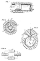
- Figures 1, 2 and 3 provide examples of several types of compressors.
- Figure 1 shows a cross-sectional view of an exemplary reciprocating compressor of the present invention.
- a tubular noncompliant fiber reinforced glass matrix cylinder liner (2) is rigidly attached to the inner surface of a cylindrical bore in the fiber reinforced resin matrix housing (1).
- a piston (3) is received within the tubular liner.
- a piston ring (4) contacts the inner surface of the liner (2) to provide a seal.
- the piston is connected to a means for reciprocally moving the piston by a connecting rod (5).
- the intake valve (6) opens on the piston downstroke, allowing low pressure gas to enter the cylinder, on the piston upstroke the intake valve (6) closes and the discharge valve (7) opens to discharge the gas at an elevated pressure.
- FIG. 2 shows a cross-sectional view of an exemplary sliding-vane rotary compressor of the present invention.
- a noncompliant fiber reinforced glass matrix composite liner (22) is rigidly attached to the inner surface of the cylindrical bore of the fiber reinforced resin matrix composite housing (21).
- a rotor (23) is eccentrically mounted in the compression chamber. Vanes (25) are slidably received in an array of radially symmetrical longitudinal slots (24). The slots extend from the outer surface of the rotor toward the central axis of the rotor.
- a resilient means, such as a spring (26) urges each vane from its slot to contact the inner surface of the liner (22).
- the rotor is rotated on its axis and low pressure gas enters the inlet (27), is compressed as it is swept toward the discharge port (28) and discharged at an elevated pressure.
- Figure 3 shows a cross-sectional view of an exemplary fixed-vane rotary compressor of the present invention.
- a noncompliant fiber reinforced glass matrix composite compression chamber liner (32) is rigidly attached to the inner wall of the housing (31).
- a rotor means (34) is received within the compression chamber and forms a planar boundary for the compression chamber at normal to the longitudinal axis of inner surface of the liner.
- a cylindrical projection (33) is eccentrically mounted on the rotor means (34).
- a vane (35) is slidably received in a slot (36) in the housing (31). The vane (35) is urged by resilient means (37) to contact the surface of the projection (33).
- the rotor In operation, the rotor is rotated on its central axis, the projection (33) sweeps along the inner circumference of the liner (32) and the working fluid enters the intake port (38) at ambient pressure and is displaced by the projection and expelled from the discharge port (39) at an elevated pressure.
- the glass matrix material of the liner may be any glass or glass-ceramic that imparts the desired high strength, thermal stability and abrasion resistance to the glass matrix composite liner of the present invention.
- Aluminosilicate, borosilicate and high silica glasses as well as mixtures of glasses are suitable matrix materials.
- Glass-ceramic materials e.g. lithium aluminosilicate
- Borosilicate glass is preferred as the glass matrix material because it is more easily processed than the other glasses and its thermal stability is adequate for purposes of the present invention.
- a borosilicate glass, known as Corning 7740 has been found to be particularly well suited to the practice of the present invention.
- the Corning 7740 glass has a tensile modulus of 9.1x10⁶psi, a density of 2.23g/cm3, a coefficient of thermal expansion of 32.5x10 ⁇ 7cm/cm°C, an anneal point of 560°C, a softening point of 821°C and a liquidus temperature of 1017°C.
- the fiber reinforcement in the glass matrix composite liner of the present invention may comprise any discontinuous fiber that exhibits a tensile strength greater than 200x103psi, a tensile modulus greater than 30x106psi, is stable at temperatures up to 1400°C, and imparts lubricity to the glass matrix composite liner.
- Pitch or polyacrylonitile (PAN) based carbon fibers are preferred. PAN carbon fibers are most preferred because they impart superior lubricity.
- a fiber reinforced glass matrix composite liner may be formed by injection molding a mixture of discontinuous fibers and glass powder as described in commonly assigned U.S. Patent No. 4,464,192, the disclosure of which is incorporated herein by reference.
- the volume fraction of fiber may range from about 10% to about 50%. A volume fraction of fiber above about 50% results in a deterioration of the wear resistance of the liner due to fiber pullout. It is preferred that the volume fraction of fiber reinforcement in the glass matrix be in the range of about 30% to about 40%.
- the resin matrix of the fiber reinforced resin matrix composite housing of the present invention is chosen to impart high strength and thermal stability.
- Polyamide resins, bismaleiimide resins and polyphenylene sulfide resins are suitable resin materials.
- Polyphenylene sulfide resins are a cost effective choice for applications in which long term exposure to temperatures above about 175°C is not anticipated and are preferred for such applications.
- RYTON® A-100 has a flexural modulus of 1.7x10⁶psi at 100°F, a tensile strength of 1.8x10³psi at 100°F and a density of 1.66g/cm3.
- RYTON® A-100 polyphenylene sulfide resin contains about 40 weight percent chopped glass fibers, so that it may not be necessary to add fibers to the RYTON® A-100 resin to obtain a suitable fiber reinforced resin matrix composite material.
- polyimide resins are preferred.
- the PMR-15 resin has a tensile modulus of 0.65x10⁶psi, a tensile strength of 7x10³psi, a density of 1.30g/cm3, and a heat deflection temperature of 330°C.
- Any discontinuous fiber reinforcement that exhibits tensile strength greater than 10x103psi, modulus greater than 10x106psi, thermal stability up to 700°C, and is wettable by the resin is suitable material for the fiber reinforcement of the resin matrix.
- Chopped glass fibers and discontinuous graphite fibers are preferred.
- the fiber reinforced resin matrix housing may be formed by conventional injection molding techniques. It is preferred that the fiber reinforcement comprise a volume fraction between about 20% and about 60%, with a range of about 35% to about 45% being most preferred.
- a preferred method for forming the fiber reinforced resin matrix composite housing is the molding process described in commonly assigned copending application Serial No. 084,368, filed August 12, 1987, entitled “Hybrid Composite Structures of Fiber Reinforced Glass and Resin Matrices", the disclosure of which is incorporated herein by reference. Briefly, the process involves molding a mass of fiber-containing uncured resin in contact with a preconsolidated glass matrix composite and curing the resin to consolidate a fiber reinforced resin matrix composite structure and simultaneously bond the resin matrix composite structure to the glass matrix composite structure.
- the surface of the preconsolidated glass matrix composite structure is pretreated to promote the adhesion of the resin matrix composite structure to the surface.
- Pretreatment of the surface may comprise cleaning or degreasing the surface or roughening the surface.
- the surface may be cleaned or degreased by, for example, contacting the surface with liquid solvent or solvent vapors. Conventional solvents, such as chlorinated solvents, are suitable.
- the surface may be roughened by, for example, sandblasting or chemical etching. Roughening and cleaning treatments may also be combined, such as sandblasting followed by solvent cleaning.
- a preferred technique for roughening the surface of the glass matrix structure comprises leaching back the glass matrix to partially expose the underlying fiber reinforcement by contacting the surface with an acid or base solution. This technique improves adhesion because the partially exposed fibers at what is to eventually comprise the glass matrix/resin matrix interface will ultimately be bonded into both matrices.
- Contacting the surface with a hydrofluoric acid solution for a time period between about 10 seconds and about 1 minute is a particularly effective chemical etching treatment.
- the most preferred pretreatment method is leaching back the glass matrix to partially expose the fiber reinforcement by immersing the preconsolidated glass matrix composite structure in concentrated hydrofluoric acid for a time period of about 10 seconds to about 20 seconds, removing the structure from the acid bath, and rinsing the surface with water.
- the structural integrity of the hybrid composite article may also be improved by providing the glass matrix composite structure with a geometrically complex surface to provide for mechanical interlocking between the glass matrix and resin matrix regions of the hybrid composite article.
- a hybrid composite article according to the present invention is formed by molding and curing a mass of fiber-containing resin in contact with a preconsolidated fiber reinforced glass matrix composite structure.
- the mass of fiber-containing resin is molded and cured by conventional processes which differ according to the particular choice of resin and according to the particular size and shape of the molded structure.
- the high temperature resistance and low thermal expansion of the preconsolidated glass matrix composite structure make the glass matrix structure amenable to a reinforced resin molding process.
- the curing of the resin matrix consolidates the resin matrix composite and simultaneously forms an integral bond between the resin matrix composite and the glass matrix composite to form the hybrid composite article.
- a hybrid composite article according to the present invention may be formed, for example, by placing one or more preconsolidated glass matrix structures in a predetermined orientation within a mold die into which a fiber reinforced resin is injected and cured.
- the air conditioner of the present invention is an air conditioner which includes a compressor of the present invention.
- Figure 4 shows a schematic diagram of a refrigeration system.
- a refrigerant fluid such as a fluorochlorocarbon, serves as the working fluid.
- the refrigerant is compressed in the compressor (41) and the compressed fluid flows to the condensor (42) for cooling.
- the cooled compressed fluid flows from the condensor (42) to the expansion valve (43) where the fluid is further cooled by rapid expansion.
- the cold fluid flows from the expansion valve (43) to the evaporator (44) where heat is exchanged between the air to be cooled and the cold refrigerant. Cooled air and warmed refrigerant exit the evaporator (44).
- the refrigerant is returned to the condensor (41) to complete the cycle.
- Samples of fiber reinforced glass matrix composite were prepared using the injection molding procedure described in U.S. Patent No. 4,464,192.
- the samples comprised 35 percent by volume of discontinuous graphite fiber (HMU, Hercules Inc.) and 65 percent by volume glass matrix (Corning 7740, Corning Glass Works).
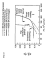
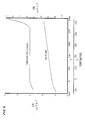
- the material so prepared was characterized by a series of tests.
- the combination of a fiber reinforced resin matrix composite housing with a noncompliant fiber reinforced glass matrix liner provides advantages over the conventional art in several ways.
- the assembly exhibits a much lower density then analogous metal assemblies.
- the low thermal conductivities of the glass matrix liner and of the resin matrix housing reduce heating of the incoming working fluid and improve compressor performance.
- the glass matrix liner offers a low coefficient of thermal expansion which permits maintenance of closer tolerances than possible with steel liners.
- the glass matrix liner provides a smoother, lower friction surface than steel liners and provides improved wear resistance.
Landscapes
- Engineering & Computer Science (AREA)
- Mechanical Engineering (AREA)
- General Engineering & Computer Science (AREA)
- Chemical & Material Sciences (AREA)
- Composite Materials (AREA)
- Compressor (AREA)
- Compositions Of Macromolecular Compounds (AREA)
- Applications Or Details Of Rotary Compressors (AREA)
- Rotary Pumps (AREA)
- Structures Of Non-Positive Displacement Pumps (AREA)
Applications Claiming Priority (2)
| Application Number | Priority Date | Filing Date | Title |
|---|---|---|---|
| US07/084,370 US4870827A (en) | 1987-08-12 | 1987-08-12 | Hybrid composite compressor |
| US84370 | 1987-08-12 |
Publications (3)
| Publication Number | Publication Date |
|---|---|
| EP0303553A2 true EP0303553A2 (de) | 1989-02-15 |
| EP0303553A3 EP0303553A3 (en) | 1989-11-29 |
| EP0303553B1 EP0303553B1 (de) | 1992-06-17 |
Family
ID=22184526
Family Applications (1)
| Application Number | Title | Priority Date | Filing Date |
|---|---|---|---|
| EP88630149A Expired - Lifetime EP0303553B1 (de) | 1987-08-12 | 1988-08-11 | Hybrid zusammengestellter Verdichter |
Country Status (8)
| Country | Link |
|---|---|
| US (1) | US4870827A (de) |
| EP (1) | EP0303553B1 (de) |
| JP (1) | JPS6460786A (de) |
| KR (1) | KR970001274B1 (de) |
| AU (1) | AU599550B2 (de) |
| BR (1) | BR8804080A (de) |
| DE (2) | DE3872101T2 (de) |
| MY (1) | MY103144A (de) |
Cited By (3)
| Publication number | Priority date | Publication date | Assignee | Title |
|---|---|---|---|---|
| EP0391182A3 (de) * | 1989-04-07 | 1991-01-16 | Leybold Aktiengesellschaft | Vakuumpumpe |
| EP0501806A1 (de) * | 1991-03-01 | 1992-09-02 | Suprex Corporation | Pumpe für verflüssigtes Kohlendioxyd |
| WO2009071384A1 (de) * | 2007-12-06 | 2009-06-11 | Continental Aktiengesellschaft | Kompressoreinheit |
Families Citing this family (11)
| Publication number | Priority date | Publication date | Assignee | Title |
|---|---|---|---|---|
| US4983463A (en) * | 1987-08-12 | 1991-01-08 | United Technologies Corporation | Hybrid composite structures of fiber reinforced glass and resin matrices |
| US5355679A (en) * | 1993-06-25 | 1994-10-18 | Phpk Technologies, Incorporated | High reliability gas expansion engine |
| JP4031062B2 (ja) * | 1995-08-11 | 2008-01-09 | 株式会社荏原製作所 | プラスチック製部品及びその製造方法 |
| JP2001082484A (ja) * | 1999-09-16 | 2001-03-27 | Nippon Mitsubishi Oil Corp | ウェアリングおよびそれを備えたポンプ |
| US6321713B1 (en) * | 2000-08-02 | 2001-11-27 | Mallen Research Corporation | Hot wall combustion insert for a rotary vane pumping machine |
| WO2011103324A2 (en) | 2010-02-17 | 2011-08-25 | Viking At, Llc | Smart material actuator capable of operating in three dimensions |
| JP2011202576A (ja) * | 2010-03-25 | 2011-10-13 | Teikoku Piston Ring Co Ltd | シリンダライナ |
| US20150337823A1 (en) * | 2012-11-08 | 2015-11-26 | Viking At, Llc | Lubricant-Free Compressor Having a Graphite Piston in a Glass Cylinder |
| ITFI20130243A1 (it) * | 2013-10-16 | 2015-04-17 | Nuovo Pignone Srl | "automatic ring valve, shutters for automatic ring valves, and method for manufacturing said shutters" |
| WO2015100280A1 (en) | 2013-12-24 | 2015-07-02 | Viking At, Llc | Mechanically amplified smart material actuator utilizing layered web assembly |
| WO2017030986A1 (en) * | 2015-08-14 | 2017-02-23 | Sabic Global Technologies B.V. | Cylinder head for compressor |
Family Cites Families (21)
| Publication number | Priority date | Publication date | Assignee | Title |
|---|---|---|---|---|
| US3419208A (en) * | 1966-06-09 | 1968-12-31 | Gen Motors Corp | Fluid flow control mechanism |
| NL147226B (nl) * | 1967-02-25 | 1975-09-15 | Philips Nv | Heetgasmotor, waarin de aan de expansieruimte grenzende zuiger is voorzien van een zuigerdop. |
| GB1289962A (de) * | 1968-09-27 | 1972-09-20 | ||
| US4086043A (en) * | 1976-12-30 | 1978-04-25 | Ingersoll-Rand Company | Rotor with plastic sheathing |
| US4209286A (en) * | 1978-09-27 | 1980-06-24 | Schwartz Kenneth P | Self lubricating vane for a rotary vane cooling system |
| US4265968A (en) * | 1979-07-02 | 1981-05-05 | United Technologies Corporation | High strength, high thermally conductive articles |
| DE2938276A1 (de) * | 1979-09-21 | 1981-04-09 | Robert Bosch Gmbh, 7000 Stuttgart | Fluegelzellenverdichter |
| US4263367A (en) * | 1979-11-07 | 1981-04-21 | United Technologies Corporation | Discontinuous graphite fiber reinforced glass composites |
| US4341826A (en) * | 1980-02-13 | 1982-07-27 | United Technologies Corporation | Internal combustion engine and composite parts formed from silicon carbide fiber-reinforced ceramic or glass matrices |
| US4362480A (en) * | 1980-04-01 | 1982-12-07 | Mitsubishi Denki Kabushiki Kaisha | Rotary roller vane pump made of specific materials |
| DE3047978A1 (de) * | 1980-12-19 | 1982-07-29 | Wabco Fahrzeugbremsen Gmbh, 3000 Hannover | Laufflaechen in kolbenmaschine |
| US4403478A (en) * | 1982-03-26 | 1983-09-13 | The United States Of America As Represented By The Secretary Of The Navy | Expander stroke delay mechanism for split stirling cryogenic cooler |
| US4428763A (en) * | 1982-05-25 | 1984-01-31 | United Technologies Corporation | Transfer molding method of producing fiber reinforced glass matrix composite articles |
| US4464192A (en) * | 1982-05-25 | 1984-08-07 | United Technologies Corporation | Molding process for fiber reinforced glass matrix composite articles |
| JPS5984991A (ja) * | 1982-11-08 | 1984-05-16 | Komatsu Ltd | 無潤滑摺動用材料 |
| US4466785A (en) * | 1982-11-18 | 1984-08-21 | Ingersoll-Rand Company | Clearance-controlling means comprising abradable layer and abrasive layer |
| US4475346A (en) * | 1982-12-06 | 1984-10-09 | Helix Technology Corporation | Refrigeration system with linear motor trimming of displacer movement |
| US4435455A (en) * | 1983-01-10 | 1984-03-06 | United Technologies Corporation | Compliant composite tubular liners of fiber reinforced glass/glass-ceramic having utility as gun barrel liners |
| JPS59188080A (ja) * | 1983-03-31 | 1984-10-25 | Mazda Motor Corp | 回転スリ−ブを有する回転圧縮機 |
| JPS627737A (ja) * | 1985-07-03 | 1987-01-14 | Ube Ind Ltd | ハイブリツド繊維強化プラスチツク複合材料 |
| FR2588618B1 (fr) * | 1985-10-16 | 1987-11-20 | Unite Hermetique | Procede de determination d'un materiau composite constitutif des pieces en mouvement d'un compresseur frigorifique hermetique et compresseur frigorifique hermetique comprenant des pieces determinees par ce procede. |
-
1987
- 1987-08-12 US US07/084,370 patent/US4870827A/en not_active Expired - Fee Related
-
1988
- 1988-08-09 AU AU20580/88A patent/AU599550B2/en not_active Ceased
- 1988-08-10 MY MYPI88000914A patent/MY103144A/en unknown
- 1988-08-11 EP EP88630149A patent/EP0303553B1/de not_active Expired - Lifetime
- 1988-08-11 DE DE8888630149T patent/DE3872101T2/de not_active Expired - Lifetime
- 1988-08-11 DE DE198888630149T patent/DE303553T1/de active Pending
- 1988-08-12 KR KR1019880010299A patent/KR970001274B1/ko not_active Expired - Lifetime
- 1988-08-12 JP JP63202618A patent/JPS6460786A/ja active Pending
- 1988-08-12 BR BR8804080A patent/BR8804080A/pt unknown
Cited By (4)
| Publication number | Priority date | Publication date | Assignee | Title |
|---|---|---|---|---|
| EP0391182A3 (de) * | 1989-04-07 | 1991-01-16 | Leybold Aktiengesellschaft | Vakuumpumpe |
| EP0501806A1 (de) * | 1991-03-01 | 1992-09-02 | Suprex Corporation | Pumpe für verflüssigtes Kohlendioxyd |
| US5193991A (en) * | 1991-03-01 | 1993-03-16 | Suprex Corporation | Liquefied carbon dioxide pump |
| WO2009071384A1 (de) * | 2007-12-06 | 2009-06-11 | Continental Aktiengesellschaft | Kompressoreinheit |
Also Published As
| Publication number | Publication date |
|---|---|
| BR8804080A (pt) | 1989-03-07 |
| MY103144A (en) | 1993-04-30 |
| DE303553T1 (de) | 1989-07-13 |
| AU2058088A (en) | 1989-02-16 |
| US4870827A (en) | 1989-10-03 |
| DE3872101D1 (de) | 1992-07-23 |
| AU599550B2 (en) | 1990-07-19 |
| KR970001274B1 (ko) | 1997-02-05 |
| JPS6460786A (en) | 1989-03-07 |
| KR890004084A (ko) | 1989-04-19 |
| EP0303553A3 (en) | 1989-11-29 |
| DE3872101T2 (de) | 1992-12-03 |
| EP0303553B1 (de) | 1992-06-17 |
Similar Documents
| Publication | Publication Date | Title |
|---|---|---|
| US4870827A (en) | Hybrid composite compressor | |
| CN101270744B (zh) | 压缩机改进结构 | |
| CN107676188B (zh) | 聚合物复合发动机组件以及加热和冷却所述组件的方法 | |
| CN107676370B (zh) | 曲轴组件及其制造方法 | |
| CN113915129B (zh) | 一种低压腔旋转式压缩机及空调器 | |
| RU2389902C2 (ru) | Напорная часть возвратно-поступательного насоса (варианты) и способ выполнения операций в нефтяной скважине данным насосом | |
| JPS60233379A (ja) | 往復ガス圧縮機 | |
| CN100404837C (zh) | 斯特林循环发动机 | |
| CN118517395A (zh) | 一种真空稳定性优异的低温真空泵 | |
| JPH0925885A (ja) | ロータリコンプレッサ及びロータリコンプレッサ用ベーン | |
| CN1328320C (zh) | 一种热塑性聚酰亚胺基空压机滑片及其制备方法 | |
| CN1033712C (zh) | 一种耐高温耐腐蚀泵及其制造方法 | |
| KR100700615B1 (ko) | 왕복동식 압축기의 토출밸브 | |
| US5651930A (en) | Composite fiber rotor vane | |
| CN211397809U (zh) | 一种用于汽车空调压缩机的活塞组件 | |
| JP2603321B2 (ja) | 耐熱性樹脂組成物およびそれを用いた内燃機関用部品 | |
| CA1091515A (en) | Impregnated castings chemically resistant to contact with halocarbon refrigerant | |
| RU2084699C1 (ru) | Поршневой компрессор с электрическим приводом | |
| JPH08323861A (ja) | 回転機械又は往復機械の機械要素 | |
| CN115467805A (zh) | 往复式活塞压缩机用的复合阀板、往复式活塞压缩机 | |
| CN211819861U (zh) | 一种空气压缩机连体气缸盖 | |
| CN218971367U (zh) | 一种去金属化的直流无刷无油压缩机 | |
| CN223964766U (zh) | 一种具有高耐磨性的空调压缩机曲轴 | |
| CN119713657B (zh) | 一种弹热回热器及其装配方法 | |
| JP3554359B2 (ja) | 圧縮機 |
Legal Events
| Date | Code | Title | Description |
|---|---|---|---|
| PUAI | Public reference made under article 153(3) epc to a published international application that has entered the european phase |
Free format text: ORIGINAL CODE: 0009012 |
|
| AK | Designated contracting states |
Kind code of ref document: A2 Designated state(s): DE FR GB IT SE |
|
| ITCL | It: translation for ep claims filed |
Representative=s name: RICCARDI SERGIO & CO. |
|
| EL | Fr: translation of claims filed | ||
| DET | De: translation of patent claims | ||
| PUAL | Search report despatched |
Free format text: ORIGINAL CODE: 0009013 |
|
| AK | Designated contracting states |
Kind code of ref document: A3 Designated state(s): DE FR GB IT SE |
|
| 17P | Request for examination filed |
Effective date: 19900502 |
|
| 17Q | First examination report despatched |
Effective date: 19910403 |
|
| GRAA | (expected) grant |
Free format text: ORIGINAL CODE: 0009210 |
|
| AK | Designated contracting states |
Kind code of ref document: B1 Designated state(s): DE FR GB IT SE |
|
| ET | Fr: translation filed | ||
| REF | Corresponds to: |
Ref document number: 3872101 Country of ref document: DE Date of ref document: 19920723 |
|
| ITF | It: translation for a ep patent filed | ||
| PLBE | No opposition filed within time limit |
Free format text: ORIGINAL CODE: 0009261 |
|
| STAA | Information on the status of an ep patent application or granted ep patent |
Free format text: STATUS: NO OPPOSITION FILED WITHIN TIME LIMIT |
|
| 26N | No opposition filed | ||
| PGFP | Annual fee paid to national office [announced via postgrant information from national office to epo] |
Ref country code: GB Payment date: 19930715 Year of fee payment: 6 |
|
| PGFP | Annual fee paid to national office [announced via postgrant information from national office to epo] |
Ref country code: SE Payment date: 19930719 Year of fee payment: 6 |
|
| PG25 | Lapsed in a contracting state [announced via postgrant information from national office to epo] |
Ref country code: GB Effective date: 19940811 |
|
| PG25 | Lapsed in a contracting state [announced via postgrant information from national office to epo] |
Ref country code: SE Effective date: 19940812 |
|
| EAL | Se: european patent in force in sweden |
Ref document number: 88630149.8 |
|
| GBPC | Gb: european patent ceased through non-payment of renewal fee |
Effective date: 19940811 |
|
| EUG | Se: european patent has lapsed |
Ref document number: 88630149.8 |
|
| PGFP | Annual fee paid to national office [announced via postgrant information from national office to epo] |
Ref country code: DE Payment date: 20020823 Year of fee payment: 15 |
|
| PGFP | Annual fee paid to national office [announced via postgrant information from national office to epo] |
Ref country code: FR Payment date: 20020828 Year of fee payment: 15 |
|
| PG25 | Lapsed in a contracting state [announced via postgrant information from national office to epo] |
Ref country code: DE Free format text: LAPSE BECAUSE OF NON-PAYMENT OF DUE FEES Effective date: 20040302 |
|
| PG25 | Lapsed in a contracting state [announced via postgrant information from national office to epo] |
Ref country code: FR Free format text: LAPSE BECAUSE OF NON-PAYMENT OF DUE FEES Effective date: 20040430 |
|
| REG | Reference to a national code |
Ref country code: FR Ref legal event code: ST |
|
| PG25 | Lapsed in a contracting state [announced via postgrant information from national office to epo] |
Ref country code: IT Free format text: LAPSE BECAUSE OF NON-PAYMENT OF DUE FEES;WARNING: LAPSES OF ITALIAN PATENTS WITH EFFECTIVE DATE BEFORE 2007 MAY HAVE OCCURRED AT ANY TIME BEFORE 2007. THE CORRECT EFFECTIVE DATE MAY BE DIFFERENT FROM THE ONE RECORDED. Effective date: 20050811 |