EP0304998A2 - Wähl-Nebenstellenanlagesystem mit schnurlosen Fernsprechern - Google Patents
Wähl-Nebenstellenanlagesystem mit schnurlosen Fernsprechern Download PDFInfo
- Publication number
- EP0304998A2 EP0304998A2 EP88201771A EP88201771A EP0304998A2 EP 0304998 A2 EP0304998 A2 EP 0304998A2 EP 88201771 A EP88201771 A EP 88201771A EP 88201771 A EP88201771 A EP 88201771A EP 0304998 A2 EP0304998 A2 EP 0304998A2
- Authority
- EP
- European Patent Office
- Prior art keywords
- base station
- security
- handset
- micro
- controller
- Prior art date
- Legal status (The legal status is an assumption and is not a legal conclusion. Google has not performed a legal analysis and makes no representation as to the accuracy of the status listed.)
- Granted
Links
Images

Classifications
-
- H—ELECTRICITY
- H04—ELECTRIC COMMUNICATION TECHNIQUE
- H04M—TELEPHONIC COMMUNICATION
- H04M1/00—Substation equipment, e.g. for use by subscribers
- H04M1/72—Mobile telephones; Cordless telephones, i.e. devices for establishing wireless links to base stations without route selection
- H04M1/725—Cordless telephones
- H04M1/727—Identification code transfer arrangements
-
- H—ELECTRICITY
- H04—ELECTRIC COMMUNICATION TECHNIQUE
- H04M—TELEPHONIC COMMUNICATION
- H04M1/00—Substation equipment, e.g. for use by subscribers
- H04M1/72—Mobile telephones; Cordless telephones, i.e. devices for establishing wireless links to base stations without route selection
- H04M1/725—Cordless telephones
- H04M1/72502—Cordless telephones with one base station connected to a single line
- H04M1/72505—Radio link set-up procedures
Definitions
- the present invention relates to a PABX cordless telephone system and particularly to the security arrangements for such a system.
- a typical domestic cordless telephone system comprises a base station which is connected to the public switching network and a handset which communicates with its associated base station by a duplex radio link.
- the handset includes a keypad so that the outgoing calls can be made via the radio link to the base station and then onwards through the public switching network.
- calls on the public switching network for a handset are relayed by the radio link from the base station which includes the necessary control circuitry.
- the number of cordless telephone systems exceeds the number of radio channels which can be allocated then there is a risk of conflict between users. Perhaps the most serious conflict is third party who has a handset making an outgoing call via a first party's base station due to the fact that both parties have handsets which operate on the same radio channel.
- a PABX system In a PABX system the situation is different from a domestic system in that the base station has to be able to communicate via respective radio channels with a plurality of handsets.
- each handset Within the system one wants each handset to be able to make and receive calls by way of the public switching network as well as to have intercom calls from one handset to another by way of the base station. In consequence part of the control function of the base station is to check continuously which channels and handsets are free.
- a multiple bit address, say a 16 bit address, of each handset in the PABX system can be altered in the manner described in European Patent Specification 0 196 834 when placed in respective battery charging sockets.
- a memory in each handset stores its respective address and channel.
- a memory in the base station has to be store the latest number of each handset and the channel allocated.
- One method of avoiding conflicts between the handsets on neighbouring PABX systems would be to address each handset in turn and obtain an appropriate acknowledgement, for example busy or free.
- a typical signalling rate is 115 bits/second and assuming that there are 10 handsets and the signalling protocol comprised a 25-bit code then including allowing time, say 20 ms, for an acknowledgement from each handset, a minimum of 3.2 seconds would be required to execute one sequence, which is unacceptable.
- An object of the present invention is to be able to execute a security check in a cordless telephone PABX system quicker whilst maintaining a high degree of security.
- a PABX cordless telephone system comprising a base station and a plurality of handsets, the base station and the handsets each having a transceiver for communication to and from each other by way of a respective duplex radio link, the base station having a micro-controller for controlling the system and each handset having a micro-controller for controlling various functions is the handset, the micro-controller in the handset including a memory in which is stored an n-bit security address code which is used in call set-up protocol with the base station and the micro-controller in the base station including a memory for storing all the assigned security address codes, wherein the micro-controller in the base station is programmed to carry-out security checks on its associated handsets by using m-bits of the n-bit security address code where m ⁇ n.
- a method of operating a PABX cordless telephone system comprising a base station and a plurality of handsets, each handset having an n-bit security address code which is also stored in the base station, wherein during call set-up protocols the full n-bit security codes are used in duplex radio links between the base station and the handsets and wherein the base station makes security checks on the handsets using m bits of the n-bit security code address, where m ⁇ n.
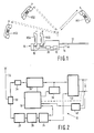
- the PABX system illustrated in Figure 1 comprises a base station 10 which is connected to the public switching network by lines 12 and to the mains power supply by way of a cable 14.
- the system further comprises five handsets HS1 to HS5.
- Each handset HS1 to HS5 is able to communicate with the base station by way of a respective duplex radio link.
- the base station 10 contains transceivers in the handsets HS1 to HS5. Control of the communications is by a micro controller 16 in the base unit 10. Under its control the handset HS1 is for example connected to the public switching network whilst an intercom call is established between the handsets HS2 and HS3.
- each handset has its own multiple bit security address code, say a 16 bit binary address code which comprises a pseudo-random number. This number can be readily changed.
- a 16 bit binary address code which comprises a pseudo-random number. This number can be readily changed.
- Recharging is carried out by placing the handset in a socket 18 in the base station 10. Each socket 18 has an electrical connection to a battery charger 20 in the base station 10.
- the micro-controller 16 includes a pseudo-random number code generator which changes the security address of the or each handset by pulsing the charging current.
- a stop facility is provided on the code generator so that the code does not change whenever the handset is replaced in the course programming and operating the handsets in the system. If desired an identification number in each handset of the system may be programmed by means of a keyboard (not shown) in the base station 10.
- FIG. 2 illustrates the basic features of the base station 10 for establishing speech communications.
- Incoming speech on the public switching network lines 12 is applied to a speech transmitter 22 which is connected to a modulator 24.
- the speed is modulated on a carrier frequency produced by an oscillator 26 and the modulated output is amplified in an R.F. power amplifier 28.
- the amplified output is applied to a duplex filter 30 which is coupled to an antenna 32.
- Incoming speech from a handset is detected by the antenna 32 and is passed via the duplex filter 30 to another filter 34.
- the filtered signal is applied to a receiver 36 from which the detected speech is applied to the speech transmitter 22 and thence onto the lines 12.
- the output of the speech transmitter 22 is connected the modulator 24 for transmission onwards to the transceiver of the other handset.
- the control of the base station 10 is by the micro controller 16.
- dialling circuit 38 When a call from a handset is to be transmitted on the public switching network then the dialling of the number to be called is effected by a dialling circuit 38 under the control of the micro controller 16. If desired dialling may be done by DTMF (dual tone multiple frequency).
- Additional control information is derived from the lines 12 by a photo-coupler 40 and is relayed to the micro controller 16.
- the handset shown in Figure 3 comprises an antenna 42 which is connected to a duplex filter 44.
- an incoming signal In the case of an incoming signal, it is filtered in another filter 46 before being applied to a receiver 48, the output of which is applied to an amplifier 50.
- An outgoing signal to a base station is amplified in an amplifier 52 before being applied to a transmitter section formed by a modulator 54, an oscillator 56 and R.F. power amplifier 58.
- a keypad 60 is connected to a micro-controller 62 which has outputs connected to the receiver 48, modulator 54 and another amplifier 64.
- the base station10 and the handsets can be made from known designs in the case of the transmitter section 24 to 28 ( Figure 2) or 54 to 58 ( Figure 3) and from standard integrated circuits such as the MC3361 in the case of the receiver, the choice being related to the frequency of operation for example on or about 900 MHz or in the 46 to 49 MHz band.
- the micro-controllers 16 and 62 are of the same type such as PCD 3315/5xx operating on a time base of 3.58 MHz.
- the amplifiers 50, 52 and 64 can be of a type TDA 7050, the speech transmitter 22 ( Figure 2) can be of a type TEA 1060 and the dialling circuit 38 may comprise a DTMF dialler type PCD 3312.
- a channel in the 46 to 49 MHz band comprises 15 KHz.
- the speech signal comprises a band between 300 Hz and 3400 Hz and control information is sent as frequency shift keyed signal centred on a pilot frequency of 7.0 kHz, say a "1" being 6.7 kHz and a "0" 7.3 kHz.
- the security code of the handset to receive the call which code is stored in a memory in the micro-controller 16 of the base station 10
- the handset compares the received security code with the security code stored in a memory associated with the micro-controller 62 ( Figure 3). If the code is confirmed the duplex channel will be enabled for the telephone conversation between the addressed handset and the base station.
- the handset When an outgoing call is to be made by the handset, then the handset initially transmits its security code which is followed by the number to be called. At the base station a comparison is made of the received security code with that stored for the particular handset, and, if confirmed then the selection information is passed on.
- the security code store in a handset is changed each time its battery is recharged. More particularly the security codes are transmitted in a suitable code such as the "Manchester" code in which after each bit the complement is transferred. Irrespective of which coding is used it is necessary for the micro-controller 62 in the handset to be synchronised with the micro-controller 16 in the base station during the time when the security code is being sent. The micro-controller 62 is able to detect when the 16 bits of the security code have been transmitted. Thereafter the micro-controller 62 activates the transmitter section of the handset and the security code is sent back to the base station micro-controller 16 via a radio link.
- a suitable code such as the "Manchester" code in which after each bit the complement is transferred.
- the old security code will be overwritten by the new security code once the transmitted and received code words are equal. Until that time the old code remains valid. Thus picking-up the handset during code transformation will have no consequence for the user because last written security code remains valid.
- the procedure will be repeated as long as the returned code is not equal to the code as transmitted by the base station.
- This technique is useful to confirm that the battery in the handset is recharged at least to an arbitrary minimum extent because there must be enough power in it to retransmit the security code back to the base station via the radio link. Cycling of successive security codes can take place every 9.4 ms.
- Figure 5 illustrates a 25-bit code word 66 which is transmitted by the handset when it is switched on and a 4-bit acknowledgement signal 68 transmitted by the base station.
- the code word 66 comprises a synchrononisation bit 70, eight bits 72 of information and a 16 bit security word 74.
- This code word 66 is sent out by the handset at a speed of 115 bits/second.
- the handset waits for 64 ms and if an acknowledgement has not been received in the meantime then it repeats the sending of the code word 55 providing the handset is still on and an acknowledgement has been received.
- the acknowledgement signal comprises an instruction that dialling data is to be sent.
- the dialling data has been formulated in accordance with a byte-oriented format to ensure the correct functioning of the entire system.
- the byte-oriented format comprises
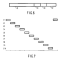
- Figure 6 illustrates a first code word transmitted by a handset to a base station.
- This code word is constituted by four parts.
- the first part comprises the 16-bit security address code 76
- the second part 78 comprises selection information for DTMF selection, if this form of dialling is available for use
- the third part 80 comprises selection information for pulse dialling selection, if this form of dialling is available for use
- the fourth part 82 is the handset identification number of the calling party.
- the first transmitted code word to be preceded by some synchronising pulses.
- the relevant dialling information is sent, for example the trunk-dialling code and the called party's number.
- redundancy has been used for transmission via the radio channel.
- the base station When the base station receives a call for one of its handsets, it transmits a code word comprising the 16 bit security code of the handset and, if applicable, the identification number of the handset.
- the identification number is necessary in those cases, there are two or more handsets forming extensions and each is allocated the same security number.
- the addressed handset acknowledges the receipt of the code word and at the same time causes its microphone amplifier and audio amplifier to be energised.
- the base station In a PABX system employing cordless telephones it is desirable for the base station to monitor the status of each the handsets, that is for example whether it is on standby, participating in a call involving the public switching network, or involved in an intercom call.
- the micro-controller In order to do this check the micro-controller interrogates each handset in turn using the control part of each channel, that is the FSK signalling centred on 7.0 kHz.
- the micro-controller 16 scans the channels sequentially by transmitting m of the n (where n > m)bits of the security code.
- the handsets respond to the security check byte sending the same m bits as were transmitted by the base station together with an indication of their statuses. Once the response has been sent the transmitters in the handsets are switched-off.
- the call set-up between the base station and the handset is delayed until the security check is completed. As the delay is less than one second then this is within the specification of many nationally approved telephone systems.
Landscapes
- Engineering & Computer Science (AREA)
- Computer Networks & Wireless Communication (AREA)
- Signal Processing (AREA)
- Mobile Radio Communication Systems (AREA)
Applications Claiming Priority (2)
| Application Number | Priority Date | Filing Date | Title |
|---|---|---|---|
| GB8720089 | 1987-08-26 | ||
| GB8720089A GB2209109A (en) | 1987-08-26 | 1987-08-26 | Pabx cordless telephone system |
Publications (3)
| Publication Number | Publication Date |
|---|---|
| EP0304998A2 true EP0304998A2 (de) | 1989-03-01 |
| EP0304998A3 EP0304998A3 (en) | 1989-07-26 |
| EP0304998B1 EP0304998B1 (de) | 1993-07-07 |
Family
ID=10622817
Family Applications (1)
| Application Number | Title | Priority Date | Filing Date |
|---|---|---|---|
| EP88201771A Expired - Lifetime EP0304998B1 (de) | 1987-08-26 | 1988-08-18 | Wähl-Nebenstellenanlagesystem mit schnurlosen Fernsprechern |
Country Status (7)
| Country | Link |
|---|---|
| US (1) | US4905272A (de) |
| EP (1) | EP0304998B1 (de) |
| JP (1) | JPS6471331A (de) |
| KR (1) | KR970002755B1 (de) |
| DE (1) | DE3882182T2 (de) |
| GB (1) | GB2209109A (de) |
| HK (1) | HK140294A (de) |
Cited By (15)
| Publication number | Priority date | Publication date | Assignee | Title |
|---|---|---|---|---|
| WO1991010333A1 (de) * | 1989-12-22 | 1991-07-11 | SIEMENS AKTIENGESELLSCHAFT öSTERREICH | Funkkommunikationsnetz auf basis digitaler ortsvermittlungsstellen |
| EP0401915A3 (de) * | 1989-06-08 | 1992-05-27 | Philips Patentverwaltung GmbH | Kennungsaustausch bei nachrichtentechnischen Geräten |
| EP0550912A3 (en) * | 1992-01-08 | 1993-08-11 | Thomson Consumer Electronics, Inc. | Use of a voltage controlled crystal oscillator in the base unit of a two-handset cordless telephone system |
| EP0554571A1 (de) * | 1992-01-08 | 1993-08-11 | Thomson Consumer Electronics, Inc. | Schnurloses Telefon mit zwei Handapparaten |
| EP0553497A3 (en) * | 1992-01-08 | 1993-08-18 | Thomson Consumer Electronics, Inc. | Frequency down conversion for a two-handset cordless telephone system using offset intermediate frequencies |
| EP0569060A3 (de) * | 1992-03-11 | 1995-02-01 | Philips Patentverwaltung | Aus schnurlosen Telefonen gebildete Nebenstellenanlage. |
| US5448764A (en) * | 1989-06-08 | 1995-09-05 | U.S. Philips Corporation | Cordless telephone set with secure communication protocol |
| WO1998003003A1 (en) * | 1996-07-11 | 1998-01-22 | British Telecommunications Public Limited Company | Telephone apparatus |
| EP0635962A3 (de) * | 1993-07-22 | 1998-05-13 | GRUNDIG Aktiengesellschaft | Verfahren zum Ermöglichen einer akustischen Überwachung beim schnurlosen Telefon |
| EP0666674A3 (de) * | 1994-02-04 | 1999-05-06 | Advanced Micro Devices, Inc. | Verfahren und Vorrichtung zur Herstellung und Überwachung einer verbesserten Funkverbindung in einem Kommunikationsystem |
| EP0923216A1 (de) * | 1997-12-04 | 1999-06-16 | Alcatel | Andockstation für Mobilfunktelefone |
| WO1999031859A1 (en) * | 1997-12-12 | 1999-06-24 | Thomson Consumer Electronics, Inc. | Initialization of handsets in a multi-line wireless phone system for secure communications |
| US6192231B1 (en) | 1996-07-11 | 2001-02-20 | British Telecommunications Public Limited Company | Telephone apparatus |
| US6832082B1 (en) | 1997-12-12 | 2004-12-14 | Thomson Licensing S.A. | Initialization of handsets in a multi-line wireless phone system for secure communications |
| DE10112462B4 (de) * | 1999-08-27 | 2006-08-31 | Helmut Schaepe | Verfahren und erweiterte Schaltungsanordnung für die Ergänzungsschaltung zum Anschließen von 2 Telefone an einer Telefonleitung mit eigener Ruf-Nr. auch mit Verbindung untereinander |
Families Citing this family (19)
| Publication number | Priority date | Publication date | Assignee | Title |
|---|---|---|---|---|
| GB9013605D0 (en) * | 1990-06-18 | 1990-08-08 | Stc Plc | Mobile communications |
| US5371782A (en) * | 1991-05-02 | 1994-12-06 | At&T Corp. | Method and apparatus for selecting a preferred service provider during a call setup in a public cordless telephone system |
| US5307370A (en) * | 1991-06-03 | 1994-04-26 | Motorola, Inc. | Secure cordless radio-telephone |
| DE4138886C1 (de) * | 1991-11-27 | 1993-04-08 | Grundig E.M.V. Elektro-Mechanische Versuchsanstalt Max Grundig Hollaend. Stiftung & Co Kg, 8510 Fuerth, De | |
| US5408419A (en) * | 1992-04-14 | 1995-04-18 | Telefonaktiebolaget L M Ericsson | Cellular radiotelephone system signalling protocol |
| US5450499A (en) * | 1992-11-25 | 1995-09-12 | Magnetic Resonance Equipment Corporation | Audio speaker for use in an external magnetic field |
| BR9510818B1 (pt) * | 1994-02-24 | 2010-08-10 | telefone celular configurado para ativação remota e para reprogramação remota. | |
| US5812951A (en) * | 1994-11-23 | 1998-09-22 | Hughes Electronics Corporation | Wireless personal communication system |
| USD419160S (en) * | 1998-05-14 | 2000-01-18 | Northrop Grumman Corporation | Personal communications unit docking station |
| US6141426A (en) * | 1998-05-15 | 2000-10-31 | Northrop Grumman Corporation | Voice operated switch for use in high noise environments |
| USD421002S (en) * | 1998-05-15 | 2000-02-22 | Northrop Grumman Corporation | Personal communications unit handset |
| US6223062B1 (en) | 1998-05-15 | 2001-04-24 | Northrop Grumann Corporation | Communications interface adapter |
| US6243573B1 (en) | 1998-05-15 | 2001-06-05 | Northrop Grumman Corporation | Personal communications system |
| US6041243A (en) * | 1998-05-15 | 2000-03-21 | Northrop Grumman Corporation | Personal communications unit |
| US6304559B1 (en) | 1998-05-15 | 2001-10-16 | Northrop Grumman Corporation | Wireless communications protocol |
| US6169730B1 (en) | 1998-05-15 | 2001-01-02 | Northrop Grumman Corporation | Wireless communications protocol |
| US7187947B1 (en) | 2000-03-28 | 2007-03-06 | Affinity Labs, Llc | System and method for communicating selected information to an electronic device |
| CA2809894C (en) | 2001-06-27 | 2017-12-12 | Skky Incorporated | Improved media delivery platform |
| CN101632289B (zh) * | 2007-03-16 | 2013-10-30 | 汤姆森许可贸易公司 | 基站级别的呼叫截听 |
Family Cites Families (7)
| Publication number | Priority date | Publication date | Assignee | Title |
|---|---|---|---|---|
| DE3315625A1 (de) * | 1983-04-29 | 1984-10-31 | Robert Bosch Gmbh, 7000 Stuttgart | Verfahren zum uebertragen von digitalen rufkennzeichen |
| JPS619039A (ja) * | 1984-06-25 | 1986-01-16 | Sony Corp | マルチチヤンネルアクセス無線方式 |
| GB2166622A (en) * | 1984-09-14 | 1986-05-08 | British Telecomm | Cordless telephone system |
| JPS61212930A (ja) * | 1985-03-19 | 1986-09-20 | Oki Electric Ind Co Ltd | 広域移動通信システムにおける移動機 |
| US4736404A (en) * | 1985-03-29 | 1988-04-05 | American Telephone And Telegraph Company, At&T Technologies Inc. | Security arrangement for cordless telephone system |
| JPS6243230A (ja) * | 1985-08-20 | 1987-02-25 | Nec Corp | コ−ドレス電話器 |
| US4700375A (en) * | 1986-10-10 | 1987-10-13 | Motorola, Inc. | Battery charging, reset, and data transfer system |
-
1987
- 1987-08-26 GB GB8720089A patent/GB2209109A/en not_active Withdrawn
-
1988
- 1988-08-18 DE DE88201771T patent/DE3882182T2/de not_active Expired - Fee Related
- 1988-08-18 EP EP88201771A patent/EP0304998B1/de not_active Expired - Lifetime
- 1988-08-22 US US07/235,253 patent/US4905272A/en not_active Expired - Fee Related
- 1988-08-23 KR KR1019880010679A patent/KR970002755B1/ko not_active Expired - Lifetime
- 1988-08-25 JP JP63209596A patent/JPS6471331A/ja active Pending
-
1994
- 1994-12-08 HK HK140294A patent/HK140294A/xx unknown
Cited By (20)
| Publication number | Priority date | Publication date | Assignee | Title |
|---|---|---|---|---|
| EP0401915A3 (de) * | 1989-06-08 | 1992-05-27 | Philips Patentverwaltung GmbH | Kennungsaustausch bei nachrichtentechnischen Geräten |
| US5448764A (en) * | 1989-06-08 | 1995-09-05 | U.S. Philips Corporation | Cordless telephone set with secure communication protocol |
| AU642697B2 (en) * | 1989-12-22 | 1993-10-28 | Siemens Aktiengesellschaft | Radio communication system based on digital localisation points |
| WO1991010333A1 (de) * | 1989-12-22 | 1991-07-11 | SIEMENS AKTIENGESELLSCHAFT öSTERREICH | Funkkommunikationsnetz auf basis digitaler ortsvermittlungsstellen |
| US5625674A (en) * | 1992-01-08 | 1997-04-29 | Thomson Consumer Electronics, Inc. | Use of a VCXO in the base unit of a two-handset cordless telephone system |
| US5392330A (en) * | 1992-01-08 | 1995-02-21 | Thomson Consumer Electronics, Inc. | Offset down conversion for a two-handset cordless telephone system |
| EP0554571A1 (de) * | 1992-01-08 | 1993-08-11 | Thomson Consumer Electronics, Inc. | Schnurloses Telefon mit zwei Handapparaten |
| US5524046A (en) * | 1992-01-08 | 1996-06-04 | Thomson Consumer Electronics, Inc. | Two-handset cordless telephone system |
| EP0550912A3 (en) * | 1992-01-08 | 1993-08-11 | Thomson Consumer Electronics, Inc. | Use of a voltage controlled crystal oscillator in the base unit of a two-handset cordless telephone system |
| EP0553497A3 (en) * | 1992-01-08 | 1993-08-18 | Thomson Consumer Electronics, Inc. | Frequency down conversion for a two-handset cordless telephone system using offset intermediate frequencies |
| EP0569060A3 (de) * | 1992-03-11 | 1995-02-01 | Philips Patentverwaltung | Aus schnurlosen Telefonen gebildete Nebenstellenanlage. |
| EP0635962A3 (de) * | 1993-07-22 | 1998-05-13 | GRUNDIG Aktiengesellschaft | Verfahren zum Ermöglichen einer akustischen Überwachung beim schnurlosen Telefon |
| EP0666674A3 (de) * | 1994-02-04 | 1999-05-06 | Advanced Micro Devices, Inc. | Verfahren und Vorrichtung zur Herstellung und Überwachung einer verbesserten Funkverbindung in einem Kommunikationsystem |
| WO1998003003A1 (en) * | 1996-07-11 | 1998-01-22 | British Telecommunications Public Limited Company | Telephone apparatus |
| US6192231B1 (en) | 1996-07-11 | 2001-02-20 | British Telecommunications Public Limited Company | Telephone apparatus |
| EP0923216A1 (de) * | 1997-12-04 | 1999-06-16 | Alcatel | Andockstation für Mobilfunktelefone |
| US6240297B1 (en) | 1997-12-04 | 2001-05-29 | Alcatel | Docking station for mobile telecommunication handset |
| WO1999031859A1 (en) * | 1997-12-12 | 1999-06-24 | Thomson Consumer Electronics, Inc. | Initialization of handsets in a multi-line wireless phone system for secure communications |
| US6832082B1 (en) | 1997-12-12 | 2004-12-14 | Thomson Licensing S.A. | Initialization of handsets in a multi-line wireless phone system for secure communications |
| DE10112462B4 (de) * | 1999-08-27 | 2006-08-31 | Helmut Schaepe | Verfahren und erweiterte Schaltungsanordnung für die Ergänzungsschaltung zum Anschließen von 2 Telefone an einer Telefonleitung mit eigener Ruf-Nr. auch mit Verbindung untereinander |
Also Published As
| Publication number | Publication date |
|---|---|
| KR890004535A (ko) | 1989-04-22 |
| GB8720089D0 (en) | 1987-09-30 |
| US4905272A (en) | 1990-02-27 |
| KR970002755B1 (ko) | 1997-03-10 |
| HK140294A (en) | 1994-12-16 |
| DE3882182D1 (de) | 1993-08-12 |
| GB2209109A (en) | 1989-04-26 |
| JPS6471331A (en) | 1989-03-16 |
| EP0304998B1 (de) | 1993-07-07 |
| DE3882182T2 (de) | 1994-01-27 |
| EP0304998A3 (en) | 1989-07-26 |
Similar Documents
| Publication | Publication Date | Title |
|---|---|---|
| US4905272A (en) | PABX cordless telephone system | |
| EP0441370B1 (de) | Schnurloses Telefonsystem im Grossraum, geeignet zum Empfang ankommender Anrufe mit einer Gruppenadresse | |
| US5758290A (en) | Cordless telephone arranged for operating with multiple portable units in a frequency hopping system | |
| US5463659A (en) | Apparatus and method of configuring a cordless telephone for operating in a frequency hopping system | |
| EP0631417B1 (de) | Verfahren und Steuereinrichtung für ein Funktelefonsystem | |
| US4144409A (en) | Mobile radio communication control system for preventing erroneous reception of control signals | |
| EP0140351B1 (de) | Mobilfunk-Übertragungssystem | |
| WO1994005101A1 (en) | Portable to portable communications in a cordless telephone system | |
| JPH0334702B2 (de) | ||
| EP0294233B2 (de) | Schnurloser Telefonapparat und Steuerungsverfahren dafür | |
| EP0921668B1 (de) | TDMA Kommunikationssystem und Verfahren | |
| JPS63176029A (ja) | コ−ドレス電話装置の接続制御方式 | |
| US5357558A (en) | Radio communication apparatus for ISDN | |
| JP3138389B2 (ja) | デジタルコードレス電話機 | |
| US6029071A (en) | Apparatus and method for synchronizing a cordless telephone base unit and multiple portable units on a common communication channel | |
| US6608889B2 (en) | Telephone having convenience feature data transfer capability | |
| KR920009152B1 (ko) | 구내 무선전화 시스템 | |
| GB2241134A (en) | Telecommunications apparatus | |
| JP3127958B2 (ja) | 無線電話システム | |
| JP2986631B2 (ja) | ディジタルコードレス電話機 | |
| KR100281968B1 (ko) | 확산 스펙트럼 방식 무선 전화기의 크래들 상태에서 무선 링크형성 방법 | |
| JP3703203B2 (ja) | 無線通信システムおよび無線通信方法 | |
| EP0683952A1 (de) | Schnurlose kommunikationsysteme | |
| JP3055478B2 (ja) | 無線電話装置 | |
| JP2783251B2 (ja) | Mca無線装置 |
Legal Events
| Date | Code | Title | Description |
|---|---|---|---|
| PUAI | Public reference made under article 153(3) epc to a published international application that has entered the european phase |
Free format text: ORIGINAL CODE: 0009012 |
|
| AK | Designated contracting states |
Kind code of ref document: A2 Designated state(s): CH DE FR GB IT LI SE |
|
| PUAL | Search report despatched |
Free format text: ORIGINAL CODE: 0009013 |
|
| AK | Designated contracting states |
Kind code of ref document: A3 Designated state(s): CH DE FR GB IT LI SE |
|
| 17P | Request for examination filed |
Effective date: 19900124 |
|
| 17Q | First examination report despatched |
Effective date: 19920113 |
|
| GRAA | (expected) grant |
Free format text: ORIGINAL CODE: 0009210 |
|
| AK | Designated contracting states |
Kind code of ref document: B1 Designated state(s): CH DE FR GB IT LI SE |
|
| REF | Corresponds to: |
Ref document number: 3882182 Country of ref document: DE Date of ref document: 19930812 |
|
| ITF | It: translation for a ep patent filed | ||
| ET | Fr: translation filed | ||
| PLBE | No opposition filed within time limit |
Free format text: ORIGINAL CODE: 0009261 |
|
| STAA | Information on the status of an ep patent application or granted ep patent |
Free format text: STATUS: NO OPPOSITION FILED WITHIN TIME LIMIT |
|
| 26N | No opposition filed | ||
| PGFP | Annual fee paid to national office [announced via postgrant information from national office to epo] |
Ref country code: GB Payment date: 19940728 Year of fee payment: 7 |
|
| PGFP | Annual fee paid to national office [announced via postgrant information from national office to epo] |
Ref country code: FR Payment date: 19940825 Year of fee payment: 7 |
|
| PGFP | Annual fee paid to national office [announced via postgrant information from national office to epo] |
Ref country code: SE Payment date: 19940826 Year of fee payment: 7 |
|
| PGFP | Annual fee paid to national office [announced via postgrant information from national office to epo] |
Ref country code: DE Payment date: 19941026 Year of fee payment: 7 |
|
| PGFP | Annual fee paid to national office [announced via postgrant information from national office to epo] |
Ref country code: CH Payment date: 19941122 Year of fee payment: 7 |
|
| EAL | Se: european patent in force in sweden |
Ref document number: 88201771.8 |
|
| ITPR | It: changes in ownership of a european patent |
Owner name: CAMBIO RAGIONE SOCIALE;PHILIPS ELECTRONICS N.V. |
|
| REG | Reference to a national code |
Ref country code: CH Ref legal event code: PFA Free format text: PHILIPS ELECTRONICS N.V. |
|
| REG | Reference to a national code |
Ref country code: FR Ref legal event code: CD |
|
| PG25 | Lapsed in a contracting state [announced via postgrant information from national office to epo] |
Ref country code: GB Effective date: 19950818 |
|
| PG25 | Lapsed in a contracting state [announced via postgrant information from national office to epo] |
Ref country code: SE Effective date: 19950819 |
|
| PG25 | Lapsed in a contracting state [announced via postgrant information from national office to epo] |
Ref country code: LI Effective date: 19950831 Ref country code: CH Effective date: 19950831 |
|
| REG | Reference to a national code |
Ref country code: CH Ref legal event code: PL |
|
| GBPC | Gb: european patent ceased through non-payment of renewal fee |
Effective date: 19950818 |
|
| PG25 | Lapsed in a contracting state [announced via postgrant information from national office to epo] |
Ref country code: FR Effective date: 19960430 |
|
| PG25 | Lapsed in a contracting state [announced via postgrant information from national office to epo] |
Ref country code: DE Effective date: 19960501 |
|
| EUG | Se: european patent has lapsed |
Ref document number: 88201771.8 |
|
| REG | Reference to a national code |
Ref country code: FR Ref legal event code: ST |
|
| PG25 | Lapsed in a contracting state [announced via postgrant information from national office to epo] |
Ref country code: IT Free format text: LAPSE BECAUSE OF NON-PAYMENT OF DUE FEES;WARNING: LAPSES OF ITALIAN PATENTS WITH EFFECTIVE DATE BEFORE 2007 MAY HAVE OCCURRED AT ANY TIME BEFORE 2007. THE CORRECT EFFECTIVE DATE MAY BE DIFFERENT FROM THE ONE RECORDED. Effective date: 20050818 |