EP0554571A1 - Schnurloses Telefon mit zwei Handapparaten - Google Patents
Schnurloses Telefon mit zwei Handapparaten Download PDFInfo
- Publication number
- EP0554571A1 EP0554571A1 EP92122129A EP92122129A EP0554571A1 EP 0554571 A1 EP0554571 A1 EP 0554571A1 EP 92122129 A EP92122129 A EP 92122129A EP 92122129 A EP92122129 A EP 92122129A EP 0554571 A1 EP0554571 A1 EP 0554571A1
- Authority
- EP
- European Patent Office
- Prior art keywords
- handunit
- base unit
- cordless telephone
- unit
- sound channel
- Prior art date
- Legal status (The legal status is an assumption and is not a legal conclusion. Google has not performed a legal analysis and makes no representation as to the accuracy of the status listed.)
- Granted
Links
- 230000005236 sound signal Effects 0.000 claims description 18
- 230000005540 biological transmission Effects 0.000 claims description 11
- 230000008878 coupling Effects 0.000 claims description 3
- 238000010168 coupling process Methods 0.000 claims description 3
- 238000005859 coupling reaction Methods 0.000 claims description 3
- 230000006835 compression Effects 0.000 claims 4
- 238000007906 compression Methods 0.000 claims 4
- 238000006243 chemical reaction Methods 0.000 claims 1
- 230000003321 amplification Effects 0.000 description 3
- 238000010586 diagram Methods 0.000 description 3
- 238000003199 nucleic acid amplification method Methods 0.000 description 3
- 230000009977 dual effect Effects 0.000 description 2
- 230000015556 catabolic process Effects 0.000 description 1
- 238000006731 degradation reaction Methods 0.000 description 1
Images


Classifications
-
- H—ELECTRICITY
- H04—ELECTRIC COMMUNICATION TECHNIQUE
- H04M—TELEPHONIC COMMUNICATION
- H04M1/00—Substation equipment, e.g. for use by subscribers
- H04M1/72—Mobile telephones; Cordless telephones, i.e. devices for establishing wireless links to base stations without route selection
- H04M1/725—Cordless telephones
- H04M1/72502—Cordless telephones with one base station connected to a single line
- H04M1/72505—Radio link set-up procedures
Definitions
- This invention concerns the field of cordless telephone instruments.
- Cordless telephone instruments for use in the home are widely available.
- Such systems comprise a base unit and a remote handunit.
- the base unit is coupled to the telephone line and communicates with the remote handunit via FM radio signals.
- a cordless telephone system a user can remove the handunit from its cradle and carry it with him a short distance from his house yet still be able to make and receive telephone calls.
- Such a cordless telephone set is known from GE cordless telephone model number 2-9675 manufactured by Thomson Consumer Electronics, Inc. Indianapolis, Indiana.
- a cordless telephone system include a single base unit and at least two remote handunits. With such a system, two users may maintain participation in a three-way conversation while being free to move about within a reasonable transmission distance from the base unit.
- signal received from one handunit is transmitted to the other handunit, and sidetone from one handunit is transmitted back to that handunit.
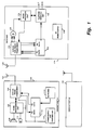
- FIGURE 1 is a block diagram of a cordless telephone system according to the subject invention.
- FIGURE 2 is a more detailed block diagram of the base unit of FIGURE 1.
- FIGURE 3 is an alternative embodiment to the arrangement of FIGURE 2.
- FIGURE 1 is a simplified illustration of a cordless telephone set comprising a first handset unit 100, a second handset unit 150, and a base unit 120. Because handset units 100 and 150 are identical (except for frequency allocation), only handset 100 will be described. Handset unit 100 receives and transmits RF signals via an antenna 102. Antenna 102 is coupled to a duplex radio transceiver unit 104 which is capable of operation in a receiver mode and in a transmitter mode. In the receiver mode, transceiver unit 104 applies received and demodulated audio signals to an audio processor unit 106 for amplification and ultimate reproduction in speaker 108.
- a duplex radio transceiver unit 104 which is capable of operation in a receiver mode and in a transmitter mode. In the receiver mode, transceiver unit 104 applies received and demodulated audio signals to an audio processor unit 106 for amplification and ultimate reproduction in speaker 108.
- transceiver 104 also provides digital data to the "receive data" (i.e., Rxdata) terminal of controller 112
- transceiver 104 receives audio signals, picked-up (i.e., detected) by microphone 110 and amplified by audio processor unit 106, for transmission to base unit 120.
- transceiver 104 receives "transmit data" (i.e., Txdata) from controller 112, for transmission to base unit 120.
- Controller 112 is coupled to a keyboard 114 for receiving keystroke commands from a user.
- Handunit 100 also includes a power supply and charging unit 116 for supplying operating power to the circuitry of the handunit.
- Base unit 120 receives and transmits RF signals via an antenna 122 to remote handunits 100 and 150.
- Antenna 122 is coupled to a duplex dual radio transceiver unit 124 which is capable of operation in a receiver mode and in a transmitter mode.
- transceiver unit 124 receives RF signals at two different frequencies from remote handunits 100 and 150 respectively, and applies received and demodulated audio signals to an audio processor unit 126 for amplification and coupling to the telephone system via a telephone interface unit 128.
- Telephone interface unit 128 is connected to the telephone system via two terminals traditionally known as tip (T) and ring (R).
- transceiver 124 also provides digital data to the "receive data" (i.e., Rxdata) terminal of controller 132.
- Controller 132 has a control terminal C by which telephone interface unit 128 can be controlled to establish communication over the telephone system.
- transceiver 124 receives audio signals, conveyed by the telephone system via telephone interface unit 128 and amplified by audio processor unit 126, for transmission to handunits 100 and 150.
- transceiver 124 receives "transmit data" (i.e., Txdata) from controller 132, for transmission to handunit 100.
- Base unit 120 also includes an AC power supply unit 136 for supplying operating power to the circuitry of the base unit.
- FIGURE 2 is a more detailed block diagram of duplex dual radio transceiver 124 of FIGURE 1.
- Antenna 122 is coupled to an RF amplifier 202 via a duplexer 200, which may be a type DPX 46/49-B10 duplexer manufactured by Soshin Electric Ltd..
- Handsets 100 and 150 transmit on different frequencies near 49 MHz.
- the signals received from the handunits are applied to mixers 205 and 235.
- Mixer 205 has a second input coupled to a local oscillator 210 for receiving an oscillator signal near 39 MHz. That is local oscillator 210 is tuned to oscillate at the difference frequency between the transmission frequency of one of the remote handunits and the first intermediate (IF) frequency of 10.7 MHz of receiver channel A.
- local oscillator 240 is tuned to oscillate at the difference between the transmission frequency of the other of the two remote handunits and the first IF frequency of 10.7 MHz of receiver channel B.
- the down-converted 10.7 MHz signals of channels A and B are applied to mixers 220 and 250, respectively. Each of mixers 220 and 250 is coupled to a second local oscillator 225 and 255, respectively.
- the received signals of channels A and B are further down-converted to a final IF frequency of 455 kHz, and applied to respective IF amplifiers 230 and 260.
- the signals are detected and expanded in detector and expander units 232 and 262 to produce baseband audio signals.
- the baseband audio signals are then summed in a summer unit 265 and coupled to the telephone line via a hybrid transformer unit 270.
- A+B sidetone signal (i.e., a portion of the received signals from both channels) is coupled from hybrid transformer unit 270 via an automatic level control unit 275 to the transmitter side of the transceiver for transmission to the handunits.
- the sidetone signal corresponding to signals received from handset A is coupled back to handset A, and the signal received from handset A is also transmitted to handset B for A-to-B communication.
- the sidetone signal corresponding to signals received from handset B is coupled back to handset B and the signal received from handset B is also transmitted to handset A for B-to-A communication.
- the signal from automatic level control unit 275 is applied to the inputs of two compressor units 280 and 282.
- the compressed audio signals are applied to control inputs of separate oscillators 284 and 286 to modulate their respective output signals.
- Oscillators 284 and 286 oscillate at different frequencies near 15 MHz.
- the modulated signals are then applied to respective frequency triplers 288 and 290 to bring their final frequencies to different frequencies near 46 MHz.
- the signals are amplified in amplifiers 292 and 294, are combined, and applied via duplexer 200 to antenna 122.
- FIGURE 3 shows an embodiment of the invention in which only a single expander and compressor are used. This arrangement recognizes that the output of expander 300 will not be exactly A+B, but that the signal A+B only occurs when both handset operators are speaking simultaneously. In normal conversation simultaneous speech does not usually occur, rather, the users of handsets A and B alternate speaking and listening. Thus, it is herein recognized that the expander can be time-shared with little noticeable degradation of performance.
Landscapes
- Engineering & Computer Science (AREA)
- Computer Networks & Wireless Communication (AREA)
- Signal Processing (AREA)
- Mobile Radio Communication Systems (AREA)
- Telephone Set Structure (AREA)
- Telephone Function (AREA)
Applications Claiming Priority (2)
| Application Number | Priority Date | Filing Date | Title |
|---|---|---|---|
| US81793492A | 1992-01-08 | 1992-01-08 | |
| US817934 | 1992-01-08 |
Publications (2)
| Publication Number | Publication Date |
|---|---|
| EP0554571A1 true EP0554571A1 (de) | 1993-08-11 |
| EP0554571B1 EP0554571B1 (de) | 1998-09-16 |
Family
ID=25224242
Family Applications (1)
| Application Number | Title | Priority Date | Filing Date |
|---|---|---|---|
| EP92122129A Expired - Lifetime EP0554571B1 (de) | 1992-01-08 | 1992-12-30 | Schnurloses Telefon mit zwei Handapparaten |
Country Status (10)
| Country | Link |
|---|---|
| US (1) | US5524046A (de) |
| EP (1) | EP0554571B1 (de) |
| JP (1) | JPH0613965A (de) |
| KR (1) | KR970006041B1 (de) |
| CN (1) | CN1026845C (de) |
| CA (1) | CA2082244C (de) |
| DE (1) | DE69227018T2 (de) |
| MX (1) | MX9300049A (de) |
| MY (1) | MY110037A (de) |
| SG (1) | SG93762A1 (de) |
Families Citing this family (6)
| Publication number | Priority date | Publication date | Assignee | Title |
|---|---|---|---|---|
| BR9510818B1 (pt) * | 1994-02-24 | 2010-08-10 | telefone celular configurado para ativação remota e para reprogramação remota. | |
| FR2718911B1 (fr) * | 1994-04-14 | 1996-06-14 | Sagem | Système de télécopie à communication sans fil. |
| US6125139A (en) * | 1995-12-29 | 2000-09-26 | Advanced Micro Devices, Inc. | Narrowband digital cordless telephone |
| US5963864A (en) * | 1996-05-31 | 1999-10-05 | Bellsouth Intellectual Property Management Corporation | Method and system for automatically connecting telephone calls to multiple devices having different directory numbers |
| US5987318A (en) * | 1996-07-31 | 1999-11-16 | Ericsson Inc. | Call conference within a home zone |
| WO2006104887A2 (en) * | 2005-03-25 | 2006-10-05 | Schulein Robert B | Audio and data communications system |
Citations (7)
| Publication number | Priority date | Publication date | Assignee | Title |
|---|---|---|---|---|
| WO1986006915A1 (en) * | 1985-05-09 | 1986-11-20 | Telefonaktiebolaget L M Ericsson | Installation with portable, wireless telephone sets |
| EP0203819A2 (de) * | 1985-05-30 | 1986-12-03 | Nec Corporation | Schnurloses Fernsprechsystem |
| EP0304998A2 (de) * | 1987-08-26 | 1989-03-01 | Koninklijke Philips Electronics N.V. | Wähl-Nebenstellenanlagesystem mit schnurlosen Fernsprechern |
| EP0305604A1 (de) * | 1987-09-03 | 1989-03-08 | Koninklijke Philips Electronics N.V. | Empfänger mit parallelen Signalstrecken |
| DE3738829A1 (de) * | 1987-11-16 | 1989-05-24 | Bosch Gmbh Robert | Fernsprechnebenstellenanlage |
| EP0316839A1 (de) * | 1987-11-19 | 1989-05-24 | Alcatel Radiotelephone | Hörverbesserungsschaltung im Falle eines Trägerschwunds in einem schmalbandigen FM/PM-Empfänger |
| EP0342707A2 (de) * | 1988-05-20 | 1989-11-23 | Siemens Aktiengesellschaft Österreich | Vorrichtung zum schnurlosen Telefonieren |
Family Cites Families (5)
| Publication number | Priority date | Publication date | Assignee | Title |
|---|---|---|---|---|
| US4476575A (en) * | 1982-12-13 | 1984-10-09 | General Electric Company | Radio transceiver |
| JPS60165131A (ja) * | 1984-02-07 | 1985-08-28 | Toyo Commun Equip Co Ltd | 内線接続機能を有した無線通信方式 |
| JPH0815354B2 (ja) * | 1986-10-30 | 1996-02-14 | 日本電気株式会社 | 無線電話装置 |
| EP0301573B1 (de) * | 1987-07-31 | 1993-04-07 | Nec Corporation | Eintragung eines neuen schnurlosen Telefons in ein bestehendes System |
| US5133002A (en) * | 1989-07-28 | 1992-07-21 | Ascii Corporation | Radiotelephone system that maintains synchronization between base and subordinate units while shifting carrier frequencies |
-
1992
- 1992-11-05 CA CA002082244A patent/CA2082244C/en not_active Expired - Fee Related
- 1992-11-27 MY MYPI92002183A patent/MY110037A/en unknown
- 1992-12-30 EP EP92122129A patent/EP0554571B1/de not_active Expired - Lifetime
- 1992-12-30 SG SG9602402A patent/SG93762A1/en unknown
- 1992-12-30 DE DE69227018T patent/DE69227018T2/de not_active Expired - Fee Related
-
1993
- 1993-01-05 KR KR1019930000032A patent/KR970006041B1/ko not_active Expired - Fee Related
- 1993-01-07 MX MX9300049A patent/MX9300049A/es not_active IP Right Cessation
- 1993-01-07 JP JP5018109A patent/JPH0613965A/ja active Pending
- 1993-01-07 CN CN93100712.7A patent/CN1026845C/zh not_active Expired - Fee Related
-
1995
- 1995-06-06 US US08/465,041 patent/US5524046A/en not_active Expired - Lifetime
Patent Citations (7)
| Publication number | Priority date | Publication date | Assignee | Title |
|---|---|---|---|---|
| WO1986006915A1 (en) * | 1985-05-09 | 1986-11-20 | Telefonaktiebolaget L M Ericsson | Installation with portable, wireless telephone sets |
| EP0203819A2 (de) * | 1985-05-30 | 1986-12-03 | Nec Corporation | Schnurloses Fernsprechsystem |
| EP0304998A2 (de) * | 1987-08-26 | 1989-03-01 | Koninklijke Philips Electronics N.V. | Wähl-Nebenstellenanlagesystem mit schnurlosen Fernsprechern |
| EP0305604A1 (de) * | 1987-09-03 | 1989-03-08 | Koninklijke Philips Electronics N.V. | Empfänger mit parallelen Signalstrecken |
| DE3738829A1 (de) * | 1987-11-16 | 1989-05-24 | Bosch Gmbh Robert | Fernsprechnebenstellenanlage |
| EP0316839A1 (de) * | 1987-11-19 | 1989-05-24 | Alcatel Radiotelephone | Hörverbesserungsschaltung im Falle eines Trägerschwunds in einem schmalbandigen FM/PM-Empfänger |
| EP0342707A2 (de) * | 1988-05-20 | 1989-11-23 | Siemens Aktiengesellschaft Österreich | Vorrichtung zum schnurlosen Telefonieren |
Also Published As
| Publication number | Publication date |
|---|---|
| US5524046A (en) | 1996-06-04 |
| DE69227018T2 (de) | 1999-04-15 |
| EP0554571B1 (de) | 1998-09-16 |
| KR970006041B1 (ko) | 1997-04-23 |
| DE69227018D1 (de) | 1998-10-22 |
| JPH0613965A (ja) | 1994-01-21 |
| MY110037A (en) | 1997-11-29 |
| CN1026845C (zh) | 1994-11-30 |
| CA2082244A1 (en) | 1993-07-09 |
| KR930017356A (ko) | 1993-08-30 |
| CA2082244C (en) | 1996-09-03 |
| MX9300049A (es) | 1993-07-01 |
| SG93762A1 (en) | 2003-01-21 |
| CN1077322A (zh) | 1993-10-13 |
Similar Documents
| Publication | Publication Date | Title |
|---|---|---|
| US5930729A (en) | Range extension accessory apparatus for cellular mobile telephones | |
| US6351653B1 (en) | Cellular telephone with simultaneous radio and cellular communications | |
| US5784685A (en) | Wireless intercom communication system and method of using same | |
| JPH11205443A (ja) | 分離型移動電話機及びその通話方法 | |
| JP2000124993A (ja) | テレビ電話 | |
| JPH1066156A (ja) | モード対応型電話機 | |
| CA2082244C (en) | Two-handset cordless telephone system | |
| US5392330A (en) | Offset down conversion for a two-handset cordless telephone system | |
| EP0550912B1 (de) | Verwendung eines spannungsgesteuerten Quarz-Oszillators in einer Feststation eines schnurlosen Telefons mit zwei Handapparaten | |
| KR100545079B1 (ko) | 자동차원격시동기능이내장된휴대폰 | |
| JP2009010900A (ja) | 無線中継機 | |
| KR0148811B1 (ko) | 주파수 공용 통신시스템의 단말기 및 그 제어방법 | |
| JPH0347019B2 (de) | ||
| JP2001102950A (ja) | 無線装置 | |
| KR970003973B1 (ko) | 복합 단말기에서의 전화번호 검색 및 자동통화로 구성 방법 | |
| JPH07288489A (ja) | 無線通信機 | |
| JPH10126305A (ja) | 中継機能付無線機 | |
| JPH04119726A (ja) | 無線電話システムのゾーン切替方式 | |
| JPH07312779A (ja) | コードレス電話機 | |
| KR20030072187A (ko) | 휴대용 무선인터폰 | |
| JPH04119727A (ja) | 無線電話システムのゾーン切替方式 | |
| JPH0360555A (ja) | コードレス電話装置 | |
| JPH05183502A (ja) | 無線電話装置 | |
| JPS63187848A (ja) | 無線受信装置 | |
| KR20000030676A (ko) | 송·수신 분리형 무선 이어폰 |
Legal Events
| Date | Code | Title | Description |
|---|---|---|---|
| PUAI | Public reference made under article 153(3) epc to a published international application that has entered the european phase |
Free format text: ORIGINAL CODE: 0009012 |
|
| AK | Designated contracting states |
Kind code of ref document: A1 Designated state(s): DE FR GB NL |
|
| 17P | Request for examination filed |
Effective date: 19940114 |
|
| 17Q | First examination report despatched |
Effective date: 19960718 |
|
| GRAG | Despatch of communication of intention to grant |
Free format text: ORIGINAL CODE: EPIDOS AGRA |
|
| GRAG | Despatch of communication of intention to grant |
Free format text: ORIGINAL CODE: EPIDOS AGRA |
|
| GRAH | Despatch of communication of intention to grant a patent |
Free format text: ORIGINAL CODE: EPIDOS IGRA |
|
| GRAH | Despatch of communication of intention to grant a patent |
Free format text: ORIGINAL CODE: EPIDOS IGRA |
|
| GRAA | (expected) grant |
Free format text: ORIGINAL CODE: 0009210 |
|
| AK | Designated contracting states |
Kind code of ref document: B1 Designated state(s): DE FR GB NL |
|
| REF | Corresponds to: |
Ref document number: 69227018 Country of ref document: DE Date of ref document: 19981022 |
|
| ET | Fr: translation filed | ||
| PLBE | No opposition filed within time limit |
Free format text: ORIGINAL CODE: 0009261 |
|
| STAA | Information on the status of an ep patent application or granted ep patent |
Free format text: STATUS: NO OPPOSITION FILED WITHIN TIME LIMIT |
|
| 26N | No opposition filed | ||
| REG | Reference to a national code |
Ref country code: GB Ref legal event code: IF02 |
|
| REG | Reference to a national code |
Ref country code: FR Ref legal event code: D6 |
|
| REG | Reference to a national code |
Ref country code: GB Ref legal event code: 746 Effective date: 20030103 |
|
| PGFP | Annual fee paid to national office [announced via postgrant information from national office to epo] |
Ref country code: FR Payment date: 20051226 Year of fee payment: 14 |
|
| PGFP | Annual fee paid to national office [announced via postgrant information from national office to epo] |
Ref country code: GB Payment date: 20061030 Year of fee payment: 15 |
|
| PGFP | Annual fee paid to national office [announced via postgrant information from national office to epo] |
Ref country code: NL Payment date: 20061203 Year of fee payment: 15 |
|
| PGFP | Annual fee paid to national office [announced via postgrant information from national office to epo] |
Ref country code: DE Payment date: 20061214 Year of fee payment: 15 |
|
| REG | Reference to a national code |
Ref country code: FR Ref legal event code: ST Effective date: 20070831 |
|
| PG25 | Lapsed in a contracting state [announced via postgrant information from national office to epo] |
Ref country code: FR Free format text: LAPSE BECAUSE OF NON-PAYMENT OF DUE FEES Effective date: 20070102 |
|
| GBPC | Gb: european patent ceased through non-payment of renewal fee |
Effective date: 20071230 |
|
| NLV4 | Nl: lapsed or anulled due to non-payment of the annual fee |
Effective date: 20080701 |
|
| PG25 | Lapsed in a contracting state [announced via postgrant information from national office to epo] |
Ref country code: DE Free format text: LAPSE BECAUSE OF NON-PAYMENT OF DUE FEES Effective date: 20080701 |
|
| PG25 | Lapsed in a contracting state [announced via postgrant information from national office to epo] |
Ref country code: NL Free format text: LAPSE BECAUSE OF NON-PAYMENT OF DUE FEES Effective date: 20080701 |
|
| PG25 | Lapsed in a contracting state [announced via postgrant information from national office to epo] |
Ref country code: GB Free format text: LAPSE BECAUSE OF NON-PAYMENT OF DUE FEES Effective date: 20071230 |