EP0305930B1 - Stranggusskokille und Verfahren zu ihrer Hochfrequenz-Oszillierung - Google Patents
Stranggusskokille und Verfahren zu ihrer Hochfrequenz-Oszillierung Download PDFInfo
- Publication number
- EP0305930B1 EP0305930B1 EP88113989A EP88113989A EP0305930B1 EP 0305930 B1 EP0305930 B1 EP 0305930B1 EP 88113989 A EP88113989 A EP 88113989A EP 88113989 A EP88113989 A EP 88113989A EP 0305930 B1 EP0305930 B1 EP 0305930B1
- Authority
- EP
- European Patent Office
- Prior art keywords
- frequency
- oscillator
- oscillators
- mold
- inner lining
- Prior art date
- Legal status (The legal status is an assumption and is not a legal conclusion. Google has not performed a legal analysis and makes no representation as to the accuracy of the status listed.)
- Expired - Lifetime
Links
Images






Classifications
-
- B—PERFORMING OPERATIONS; TRANSPORTING
- B22—CASTING; POWDER METALLURGY
- B22D—CASTING OF METALS; CASTING OF OTHER SUBSTANCES BY THE SAME PROCESSES OR DEVICES
- B22D11/00—Continuous casting of metals, i.e. casting in indefinite lengths
- B22D11/16—Controlling or regulating processes or operations
- B22D11/18—Controlling or regulating processes or operations for pouring
-
- B—PERFORMING OPERATIONS; TRANSPORTING
- B22—CASTING; POWDER METALLURGY
- B22D—CASTING OF METALS; CASTING OF OTHER SUBSTANCES BY THE SAME PROCESSES OR DEVICES
- B22D11/00—Continuous casting of metals, i.e. casting in indefinite lengths
- B22D11/04—Continuous casting of metals, i.e. casting in indefinite lengths into open-ended moulds
- B22D11/053—Means for oscillating the moulds
-
- B—PERFORMING OPERATIONS; TRANSPORTING
- B22—CASTING; POWDER METALLURGY
- B22D—CASTING OF METALS; CASTING OF OTHER SUBSTANCES BY THE SAME PROCESSES OR DEVICES
- B22D11/00—Continuous casting of metals, i.e. casting in indefinite lengths
- B22D11/04—Continuous casting of metals, i.e. casting in indefinite lengths into open-ended moulds
-
- B—PERFORMING OPERATIONS; TRANSPORTING
- B22—CASTING; POWDER METALLURGY
- B22D—CASTING OF METALS; CASTING OF OTHER SUBSTANCES BY THE SAME PROCESSES OR DEVICES
- B22D11/00—Continuous casting of metals, i.e. casting in indefinite lengths
- B22D11/16—Controlling or regulating processes or operations
-
- B—PERFORMING OPERATIONS; TRANSPORTING
- B22—CASTING; POWDER METALLURGY
- B22D—CASTING OF METALS; CASTING OF OTHER SUBSTANCES BY THE SAME PROCESSES OR DEVICES
- B22D11/00—Continuous casting of metals, i.e. casting in indefinite lengths
- B22D11/16—Controlling or regulating processes or operations
- B22D11/166—Controlling or regulating processes or operations for mould oscillation
Definitions
- This invention relates to a method of oscillating a mold for continuous casting at high frequencies and a mold oscillated by such a method according to the preambles of claims 1 and 8, respectively. More particularly, it relates to methods of oscillating at high frequencies molds that are used in the continuous casting of billets, blooms and slabs of metals and molds that are oscillated at high frequencies while such semi-finished products of metals are being continuously cast.
- oscillators high-frequency oscillating means
- Fig. 1 shows an example of a continuous caster mold 1 provided with oscillators 9a to 9l.
- the mold 1 has an inner lining of copper 4 on the inside of broad-face plates 2 and narrow-face plates 3.
- the inner lining 4 is oscillated by the oscillators 9a to 9l connected thereto.
- To the oscillators 9a to 9l are connected a frequency generator 6, a power setter 7 and an amplifier 8 successively, as shown in Fig. 2.
- the frequency generator 6, power setter 7, amplifier 8 and oscillators 9a to 9l constitute a set of oscillating means 5.
- the oscillating means 5 sets the frequency and power with which the inner lining 4 is oscillated.
- Graph (a) of Fig. 4 shows how offsetting occurs at point P1.
- Dotted line shows the high-frequency wave from the oscillator A
- chain line shows that from the oscillator B
- solid line indicates the composite wave obtained by combining the two, all at point P1.
- graph (b) of Fig. 4 shows the offsetting condition at point P2.
- the difference between the high-frequency waves generated by adjoining oscillators for the oscillation of the inner lining is kept within the limit at which beat is produced.
- the frequency of the waves generated by one oscillator can be varied by controlling the frequency setter. But if the frequency of an oscillator (of the electrostrictive or magnetostrictive type) that produces the maximum amplitude at frequency f0 is lowered under (f0 - 1) KHz or raised above (f0 + 1) KHz, the amplitude will become very small as shown in Fig. 5.
- the method of JP-A-62-57742 greatly varies the frequencies of the individual oscillators. But if the oscillators have the same oscillating characteristic, the amplitude of high-frequency waves produced by some oscillators is then decreased so greatly, as mentioned previously, that the inner lining is not oscillated with large enough amplitudes. If, on the other hand, oscillators of different types having different oscillating characteristics are used, difficult problems will arise in the control and management thereof.
- the separately excited oscillation generator that drives the oscillator is an open-loop control system in which power varies with variations in load (or variations in impedance). Therefore, it has been difficult to keep constant the amplitude of oscillation. With light loads, the amplitude of oscillation varies greatly as frequency varies, as indicated by dotted lines in Fig. 6. Such oscillations are commonly controlled by such automatic frequency tracking constant amplitude control circuits as are shown in Figs. 7 and 8.
- the impedance of the oscillator is expressed as the sum of the control impedance ⁇ d that is independent of oscillation and the control impedance ⁇ m that depends on oscillation. Therefore, the voltage proportional to oscillation is obtained by subtracting the voltage drop due to the control impedance ⁇ d from the voltage at the terminal of the oscillator.
- the bridge circuit of an oscillator and impedances ⁇ 1 to ⁇ 3 shown in Fig. 7 is an example of concrete sensing methods commonly employed for the detection of the output voltage ⁇ 2 that is proportional to ⁇ m ⁇ .
- Automatic frequency tracking is accomplished by means of a closed circuit formed by a high-frequency oscillator amplifier circuit 14 (transfer function in the amplifier circuit: ⁇ ) and the oscillation sensing circuit shown in Fig. 7, which constitutes a feedback circuit 17 (transfer coefficient in the beedback circuit: ⁇ ).
- the constant amplitude control circuit shown in Fig. 8 compares, in a voltage comparison control circuit 13, an output signal preliminarily set by the amplitude setter 12 with a signal produced by amplifying the voltage E2 from the oscillation sensing circuit by a voltage input amplifier 18. Then, the voltage comparison control circuit 13 inputs a control signal into the oscillator amplifier circuit 14 consisting of a resonant phase circuit 15 and an output matching inverter 16 to control the output to the oscillator so that constant amplitude is maintained at all times.
- JP-A-59-197351 and JP-A-59-197348 disclose methods of preventing such cracking and erosion by covering the weak spot in the water-cooled oscillated surface with a sheet of cushioning material or alloyed metal. Although effective in decreasing the occurrence of cracking and erosion, those methods are not without problems. In the course of long-time service, for example, water may penetrate into a space between the attached covering material and the water-cooled oscillated surface, causing erosion. The covering material coming off may clog up the cooling water passage. A more important problem is that the covered portion of the inner lining is not cooled adequately. Such being the case, development of a better oscillated mold capable of withstanding long-time service has been awaited.
- Oscillators are usually cooled by water-cooling, air-purging or other means as overheating can result in their breakage. If any of the oscillators malfunctions, the composite oscillation applied to the mold will become different from the originally intended one, thereby impeding the smooth implementation of the continuous casting operation. Permitting no water cooling because of the insulation consideration necessitated by the applied voltage as high as, for example, 4000 V P-P , electrostrictive oscillators are cooled by air-purging etc. Because air-purging and other similar cooling methods are not so effective as water-cooling, operation of the electrostrictive oscillators should be watched carefully.
- An object of this invention is to provide a method of constantly imparting desirable oscillations to the whole surface of the inner lining near the meniscus in a continuous caster mold equipped with a large number of oscillators having the same oscillating characteristic by controlling the interference between the high-frequency waves transmitted by the individual oscillators.
- Another object of this invention is to provide a method of constantly imparting desirable oscillations to the whole surface of the inner lining near the meniscus in a continuous caster mold equipped with a plurality of such high-frequency oscillators that the frequencies of oscillations produced by any two adjoining oscillators are differentiated by arbitrarily varying the frequency of each oscillator and permitting a constant amplitude control.
- Still another object of this invention is to provide an oscillated mold that produces no cracking or erosion on the water-cooled oscillated surface of the inner lining even if used over a long period of time.
- Yet another object of this invention is to provide an oscillated mold equipped with an easy-to-use monitoring device that permits the operator to learn that the individual oscillators on the mold are accomplishing the desired oscillation.
- two adjoining oscillators oscillate the inner lining at right angles to the surface thereof at different frequencies.
- the oscillators may be either of the electostrictive type or of the magnetostrictive type.
- one oscillator may be chosen as a base oscillator, with the frequencies of oscillations produced by the other oscillators gradually decreased or increased according to the distance at which such oscillators stand away from the base oscillator.
- the frequencies of oscillations applied by the individual oscillators on the inner lining may be varied with time, either intermittently or continuously.
- a base oscillator furthermore, a first oscillation mode, in which the frequencies of oscillations produced by the other oscillators are gradually decreased according to the distance at which such oscillators stand away from the base oscillator, and a second oscillation mode, in which the frequencies of oscillations are gradually increased according to the same distance, may be set.
- the inner lining may be alternately oscillated in the first and second modes that are switched with time, either intermittently or continuously.
- this invention uses oscillators of the same type having the same oscillating characteristic. This facilitates oscillation control and permits reducing equipment cost.
- power supply to the oscillators may be performed through a high-frequency output transformer, with the product of the d.c. voltage and d.c. current on the primary side of the transformer controlled so that the amplitude of the produced oscillations is kept constant. It is also possible to detect the d.c. voltage and d.c. current on the primary side of the high-frequency output transformer for use in the feedback control thereof.
- control circuit according to this invention which controls frequency by a simple separate excitation method and controls amplitude by controlling power supply, is not costly to make and easy to maintain.
- This invention has made it possible to arbitrarily vary the frequency of individual oscillators and to perform constant amplitude control. Consequently, the entire surface of the mold inner lining near the meniscus can now be oscillated as desired.
- a continuous caster mold oscillated at high frequencies is made up of an inner lining fabricated from copper or copper alloy and a backup outer plate, with a cooling water passage provided between the inner lining and outer plate.
- the water-cooled surface of the inner lining is nickel-plated.
- the nickel-plated surface may further be plated with chromium.
- This invention has drastically reduced the cracking and erosion in the water-cooled oscillated surface, thereby remarkably prolonging the service life of the oscillated mold.
- the continuous caster mold oscillated at high frequencies may also be equipped with a temperature sensor to measure the temperature at the surface of the oscillator, a temperature checker that checks if the surface temperature of the oscillator is within the desired range, and an alarm that actuates a signal when the surface temperature is outside the desired range.
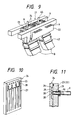
- FIG. 9 shows a mold and the surroundings thereof.
- a mold 21 consists of an outer wall made up of broad-face water boxes 22 and narrow-face back plates 23.
- An inner lining 24 is attached to each of the broad-face water boxes 22 and narrow-face back plates 23 by means of fastening bolts (not shown).
- the inner lining 24 also has a plurality of grooves 27 cut in one surface thereof. The junctures 26 and grooves 27, in combination, provide cooling water passages between the inner linings and the broad-face water boxes 22 and narrow-face back plates 23.
- Connecting seats 28 are provided in the oscillating segment 25.
- the broad-face water boxes 22 and narrow-face back plates 23 also have holes 29 into which connecting rods are inserted.
- a connecting rod 10 of an oscillator 9 passes through a hole 29. With the tip of the connecting rod 10 screwed into a connecting seat 28, the oscillator 9 is fastened to the inner lining 24.
- the oscillators 9 are disposed along a line where the surface of liquid metal contacts the inner linings 24 of the mold 21 or in the vicinity thereof, and spaced apart from each other at appropriate intervals.
- the inner lining 24 is fabricated from copper or copper alloy having high thermal conductivities, and cooled on the outer side.
- the inner lining 24 is oscillated at high frequencies, as mentioned previously, to prevent the liquid metal from sticking thereto.
- the thickness of the inner lining 24 should preferably be as thin as possible.
- the thickness of commonly used inner linings is between a few millimeters and tens of millimeters.
- the inventors studied the causes for the cracks and erosion that occur in the water-cooled oscillated surface 30. From the studies, it was found that such cracks and erosion were due to what is known as cavitation erosion.
- the running cooling water and high-frequency oscillation alternately build up high and low pressures in some area of the water-cooled oscillated surface 30.
- the resulting formation and collapsing of bubbles at and near the interface between the water-cooled oscillated surface 30 and cooling water cause a damage to the water-cooled oscillated surface 30.
- nickel plating or a combination of nickel and chromium plating is highly effective in preventing such cavitation erosion. While pure nickel plating serves the purpose right, a nickel alloy containing 2 persent to 8 percent of iron is preferable because of the better adherence to copper or copper alloy and the hardness as high as Hv 350.
- the nickel alloy coating having such properties continuously protects the water-cooled oscillated surface even after an over-coated layer of chromium has worn off.
- the nickel coating is between 0.01 mm and 1 mm in thickness. Heavier thickness providing greater durability is preferred.
- the chromium coating provided over an undercoat of nickel is hard enough to provide adequate durability against cavitation erosion. Provided over a nickel coating, the chromium coating adheres firmly enough to provide adequate protection to the water-cooled oscillated surface 30 over a long time.
- the thickness of the chromium coating usually is between 10 ⁇ m and 50 ⁇ m.
- the nickel plating or the combination of nickel and chromium plating may be applied either over the entirety of the water-cooled oscillated surface 30 or over a localized area or areas that are susceptible to heavy cavitation erosion.
- an oscillating device 31 comprises a frequency generator 32, a power setter-comparator 33, an output matching inverter 34 and an output transformer 35 that are connected one after another.
- the output matching inverter 34 supplies power to an oscillator 9 through the output transformer 35 and an impedance matching coil 36.
- a shunt 38 and a voltage divider 41 are connected to the output matching inverter 34. While the shunt 38 detects the current on the primary side of the output transformer, the voltage divider 41 detects the voltage thereon. Signals actuated on detecting such current and voltage are amplified by amplifiers 39 and 42 and then input into a power control circuit 37 through arithmetic circuits 40 and 43.
- the function of the arithmetic circuits 40 and 43 is to find the square root of the output current and voltage from the amplifiers 39 and 42. While input power is detected, output power is fed into the power setter-comparator 33 for comparison with the preset power level. By so doing, produced power is always kept equal to the preset power level.
- the oscillator 9 is of the electrostrictive type, producing high-frequency oscillations when actuated by the power from the output transformer 35. Each oscillator 9 oscillates at high frequencies the inner lining 24 through the connecting rod 10. Having the same oscillating characteristic, oscillators 9 are interchangeable. This feature not only permits considerable saving in equipment cost but also facilitates the design of mold oscillation pattern by simulation or other technologies.
- a frequency generator 51 shown in Fig. 13 is of the type just described.
- the frequency generator 51 consists essentially of a constant frequency generating circuit 52, a sweep generating circuit 56, a frequency counter 63, a BCD (binary coded decimal) system 65 and an output unit 67.
- the constant frequency generating circuit 52 equipped with a frequency setter 53 is used when there is no need to vary the frequency of oscillation with time.
- the sweep generating circuit 56 having a center frequency setter 57, a frequency scanning width setter 58 and a cycle period setter 59 is used when the frequency of oscillation must be varied with time. Switching from the constant frequency generating circuit 52 to the sweep generating circuit 56 and vice versa is accomplished by means of a changeover switch 69.
- the frequency counter 63 detects the frequency at which the inner lining 24 of the mold 21 is oscillated.
- the BCD system 65 determines whether the oscillator 9 should be oscillated with constant frequency or sweep frequency and performs switching from one mode to the other.
- the output unit 67 has a plurality of output terminals 68, with each of which connected to the power setter-comparator 33 in the oscillating device 31.
- the output unit 67 sends out signals that determine the frequency of oscillations to be produced by the oscillator.
- the frequency generator 51 permits phase matching among a plurality of oscillators that produce oscillations of the same frequency. When oscillations of more than one frequency are produced, as many frequency generators 51 as the number of different frequencies involved are employed.
- liquid steel M is poured through a tundish (not shown) and an immersion nozzle 45 into the mold 21 while oscillating the inner lining 24 with the oscillators 9.
- liquid steel M forms a bloom M, which is then pulled out of the mold 21 by means of many pinch rolls 47 disposed below the mold.
- the frequencies of oscillations to be produced by the individual oscillators are set so that the frequencies for any two adjoining oscillators are not the same.
- maximum amplitude is obtained at frequency f0.
- the frequency for an oscillator is set below (f0 - 1) KHz or above (f0 + 1)KHz, the amplitude of the high-frequency waves produced by that oscillator attenuates so sharply, as shown in Fig. 5, that the composite amplitude of the high-frequency waves produced by the individual oscillators also reduces remarkably.
- the amplitude of each oscillator should preferably be kept between the maximum amplitude A1 and the amplitude equal to A1 x 70 %.
- frequency must be controlled within the range of 2 KHz between (f0 - 1) KHz and (f0 + 1) KHz, as is obvious from Fig. 5. Because the different frequencies for different oscillators are set within the range of (f0 - 1) KHz to (f0 + 1) KHz, the differences among the frequencies for the individual oscillators are not larger than 2 KHz.
- the frequencies of oscillations produced by two adjoining oscillators are differentiated, as, for example, by increasing the frequency of oscillation produced by oscillator A as shown in Fig. 3, the relative phases of the high-frequency waves produced by oscillators A and B vary every moment. Therefore, the oscillations produced by the two oscillators do not always overlap each other at point P1, as shown in Fig. 14 (a) and (b). Similarly, oscillations from the two oscillators do not always cancel each other at point P2, thus producing an oscillation of a composite amplitude as at point P1.
- This composite amplitude can be expressed as shown at (b) of Fig. 15 with respect to the oscillating point x on the mold. As is obvious, the composite amplitude is always low in some localized areas.
- the appropriate frequency of oscillation is from 5 KHz to 50 KHz. If frequency is under 5 KHz, audible sound will exceed the level appropriate for the working environment. If, on the other hand, frequency is over 50 KHz, friction between the mold and the solidifying shell will not be reduced.
- the difference in frequency between individual oscillators is 2 KHz maximum, as mentioned before, and 0.01 KHz minimum. The desired effect will not be obtained if frequency is below 0.01 KHz.
- the inner lining of the mold should preferably be oscillated with an amplitude of 1 ⁇ or over. So long as adequate power is supplied and the amplitude of oscillation is not smaller than 1 ⁇ , oscillators producing oscillations of different frequencies may be disposed in any way. But if supplied power is inadequate for obtaining the desired amplitude, the frequency of oscillations produced by other oscillators than the base oscillator must be gradually decreased or increased with the distance of such oscillators from the base oscillator. This arrangement permits the mold to be oscillated with large amplitude despite the inadequate power supply. Because the directional amplitude distribution of beat frequency repeatedly changes with time, a uniform desirable amplitude distribution is obtainable at given intervals in all areas of the mold.
- Fig. 16 shows models of frequency for individual oscillators under condition just described.
- Graph (a) of Fig. 16 shows an example in which the frequencies for oscillators 9a to 9b in Fig. 1 are varied disorderly.
- Graph (b) shows an example in which oscillator 9a is chosen as the base oscillator. The frequency of oscillation for oscillators 9b, 9c and 9d is gradually decreased as the distance from the base oscillator 9a increases.
- Graph (c) shows a similar example in which oscillator 9b serves as the base oscillator.
- Graph (d) shows another similar example in which oscillator 9c serves as the base oscillator.
- Graph (e) shows still another similar example in which oscillator 9d serves as the base oscillator.
- the amplitude distribution of beat frequency in case (a) has no directionality. Therefore, the effect obtained in case (a) is smaller than the effects in cases (b) to (e) in which the amplitude distribution of beat frequency is directional.
- reference frequency is determined by oscillating the inner lining by means of oscillators disposed around the periphery of the mold at appropriate intervals. A given amount of power is supplied to the oscillators, one at a time. A point at which current supply to the oscillator becomes minimum is chosen as the dip point. The frequency at the dip point is defined as the resonance frequency. The mean of the resonance frequencies for all oscillators mounted on the mold is defined as the reference frequency.
- Fig. 17 shows an example of frequency measured at the dip point In this example, the base frequency obtained by averaging all resonance frequencies was 18.1 KHz.
- frequencies determined on the basis of the reference frequency are assigned to the individual oscillators, within the limits of 2 KHz.
- the variety of assigned frequencies is determined according to the size of the mold, performance of the oscillators and other parameters. Usually, two to six different frequencies are assigned. The frequencies thus chosen are assigned to individual oscillators by considering the size of the mold, performance of the oscillators and other parameters. In the aforementioned example, two frequencies, one of which being the reference frequency of 18.1 KHz, were used. The other frequency that affords the maximum amplitude was empirically determined on the basis of the reference frequency of 18.1 KHz. The other frequency thus determined was 18.5 KHz. When three different frequencies are used, an intermediate frequency between the other two is chosen as a third frequency.
- the three frequencies are 18.1 KHz, 18.3 kHz and 18.5 KHz.
- a third and a fourth frequency are determined by equally dividing the range between the other two frequencies.
- four frequencies are 18.1 KHz, 18.23 KHz, 18.36 KHz and 18.5 KHz.
- Assignment of frequencies should not be limited to the method just described.
- two frequencies may be such that are equally away from the reference frequency on both sides thereof, each affording the maximum amplitude. Such frequencies are empirically determined on each mold. If the reference frequency is 18.1 KHz, for example, the two frequencies may be 17.9 KHz and 18.3 KHz. When three or four frequencies are used, the remaining one or two frequencies are determined by equally dividing the difference of 0.4 KHz between 17.9 KHz and 18.3 KHz.
- Fig. 18 (a) and (b) show an example in which three frequencies are used.
- case (c) the frequencies for other oscillators than the base oscillator are gradually decreased with the distance from the base oscillator.
- the amplitude in case (c) is much larger than in cases (a) and (b) in which oscillators are arranged differently.
- Fig. 19 shows a case in which four different frequencies are used, with the frequencies for other oscillators than the base oscillator being gradually decreased with the distance from the base oscillator.
- the amplitude of the oscillator is constant.
- the oscillation of a mole inner lining requires a heavier load than that of, for example, an ultrasonic cleaner.
- An oscillating device 31 shown in Fig. 12 always keeps output power at the preset power level, as described previously. Keeping output power at a constant level permits keeping the amplitude of frequency at a substantially constant level. Output power may vary when impedance varies before or after liquid metal is poured or when the temperature of the oscillator varies. Even under such conditions, the amplitude of frequency can be maintained at a substantially constant level by means of constant power control.
- Attenuation of amplitude in the trough of a standing wave reduces if the mold is oscillated by oscillators assigned with different frequencies varied within the range of (f0 -1) KHz to (f0 + 1) KHz as mentioned before.
- the resulting composite amplitude might make no cyclic motion unless some special provision is made.
- some portions of the mold inner lining may be oscillated with large amplitudes, but other portions will be at all times oscillated with small amplitudes. Liquid metal sticks to the oscillated mold where the amplitude of oscillation is small. But the amplitude of oscillation can be increased by changing the frequency of oscillations of individual oscillators with time.
- ⁇ a to ⁇ d can be set as follows by adjusting the frequency generator connected to each oscillator: ⁇ max - ⁇ min ⁇ 2 KHz (7) where
- a fraction of second t (for example, from 0.1 second to 1 second) after time T1 oscillation frequencies of the oscillators are changed as follows: a: ⁇ ' a , b: ⁇ ' b , c: ⁇ ' c , and d: ⁇ ' d ⁇ ' a to ⁇ ' d are all set to satisfy equations (7) and (8).
- Oscillation frequencies of the oscillators are again changed as follows a fraction of second t after time T2: a: ⁇ " a , b: ⁇ " b , c: ⁇ " c , and d: ⁇ " d ⁇ " a to ⁇ " d are also set to satisfy equations (7) and (8).
- the frequencies of oscillations with which the inner lining of the mold is oscillated are changed with time, either intermittently or continuously.
- Fig. 21 shows the oscillating conditions of a mold oscillated at the following frequencies by the oscillators 9a to 9d.
- a ⁇ a KHz
- b ( ⁇ a - 1) KHz
- c ⁇ a KHz
- d ( ⁇ a - 1) KHz
- Fig. 21 shows the oscillating condition up to a fraction of second t after the start of oscillation at (a), that between a fraction of second t and 2 seconds after the start at (b), that between 2 seconds and 3 seconds after the start at (c), that between 3 seconds and 4 seconds after the start at (d) and that between 4 seconds and 5 seconds after the start at (e).
- Dotted lines in each graph defines the range of maximum amplitude in each time span. Overlapping each other oscillations of the individual oscillators form the wave fluxes as indicated by dotted lines in Fig. 21.
- the wave fluxes change with time as shown at (a) through (d), competing a whole cycle at (e).
- the cycle consisting of steps (a) to (e) is repeated with the passage of time.
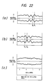
- Graph (a) of Fig. 22 shows the contour that is obtained when curves in (a) to (e) of Fig. 21 are drawn, one over another, in one chart. This shows the maximum amplitude attained at different points of a mold in the course of one cycle.
- Graph (a) of Fig. 22 shows that point P1 of the mold is always oscillated with a favorable large amplitude. In contrast, point Q1 is always oscillated with an undesirable small amplitude. This means that seizure or sticking of liquid metal is likely to occur at point Q1.
- Graph (b) of Fig. 22 shows the maximum amplitude attained at different points of a mold in the course of one cycle with the following setting: a: ⁇ a KHz, b: ( ⁇ a + 1) KHz, c: ⁇ a KHz and d: ( ⁇ a + 1) KHz.
- the oscillation frequency of each oscillator is set at a given level for a fraction of second t1 (for example, between 0.1 second and 1 second) as shown in (a) of Fig. 22.
- the oscillation frequency of each oscillator is kept at another level for a fraction of second t2 (for example, between 0.1 second and 1 second) as shown in (b) of Fig. 22. Consequently, the maximum amplitude of oscillation applied to the mold during the period t1 + t2 becomes uniform throughout the mold, whereby no point of the mold is any longer oscillated with small amplitudes.
- the oscillation frequency of each oscillator can be varied with time by use of the frequency generator 51 shown in Fig. 13.
- the center frequency setter 57 sets frequency ⁇ a and the frequency scanning width setter 58 sets frequency ⁇ ' a .
- the cycle period setter 59 sets a cycle period t with which frequency ⁇ a is switched to frequency ⁇ ' a .
- any of the oscillators 9a to 9d shown in Fig. 1 may be chosen as the base oscillator. If the oscillator 9a is chosen as the base oscillator, the oscillation frequencies of the oscillators at a specific time T1 are set according to setting I.
- equation (7) becomes 0 ⁇ ⁇ a - ⁇ d ⁇ 2 KHz (7')
- equation (8) becomes ⁇ a > ⁇ b > ⁇ c > ⁇ d (8')
- Oscillation of the mold is continued by intermittently or continuously switching, with time, from setting I to setting II, and then from setting II to setting I, and so forth.
- Graph (a) in Fig 23 shows the maximum amplitude attained in the course of a single cycle at different points of a mold oscillated with setting I.
- oscillator a serves as the base oscillator and a: ⁇ a KHz
- b ( ⁇ a - 0.3) KHz
- c ( ⁇ a - 0.6) KHz
- d ( ⁇ a - 0.9) KHz.
- the wave flux with setting I forms a beat wave that moves from oscillator a to oscillator b with a group velocity. Therefore, maximum amplitudes obtained during a single cycle at different points of the mold are more uniform than those shown in graph (a) of Fig. 22.
- the contour shows the maximum amplitudes of oscillation applied to different points of the mold during the period t3 + t4. As can be seen, the amplitude distribution in (c) of Fig. 23 is more uniform than that shown in (c) of Fig. 22.
- Fig. 24 shows different examples in which different oscillators serve as the base oscillator.
- the oscillator 9b serves as the base oscillator in (a), the oscillator 9c in (b), and the oscillator 9d in (c). While solid line indicates setting I, dotted line shows setting II.
- Fig. 25 shows an example of an oscillator equipped with a thermocouple at (a) and (b).
- a thermocouple 71 is fastened to a plate 73, with the tip of the thermocouple 71 inserted into a hole 74 provided in the plate 73.
- a fastener 76 prevents the thermocouple 71 from coming off the plate 73.
- the plate 73 carrying the fastened thermocouple 71 is fastened to an oscillator 9 by means of resin or other adhesive.
- Fig. 26 shows an example of surface temperature distribution in an oscillator at work.
- the temperature distribution curves shown in (a) and (b) of Fig. 26 will change when the amplitude of oscillator 9 is varied. In the vicinity of the tip (b), for example, a highly reproducible surface temperature having a close correlationship with amplitude appears. As such, the operation of the oscillator 9 is monitored, using the surface temperature determined at a specific point on the surface thereof as a parameter. If the relationship between the surface temperature and amplitude of each oscillator 9 has been grasped in advance, high-precision monitoring will become possible.
- Fig. 27 is an overall block diagram of a monitoring system.
- the data on the surface temperature of the oscillator obtained by a thermocouple 71 is sent to a surface temperature checking device 82.
- a surface temperature limit setter 84 sets the upper and lower limits of the surface temperature of an oscillator.
- a warning device 83 sets off an alarm when the surface temperature checking device 82 finds that the surface temperature of the oscillator is either above the upper limit or below the lower limit.
- An arithmetic unit 85 performs arithmetic processing on the delivered temperature information, with the result output to the power setting-comparator 33 shown in Fig. 12.
- this invention should not be considered as being limited to the examples described hereabove.
- this invention is applicable to the continuous casting of billets or slabs, instead of blooms.
- the oscillators may be of the magnetostrictive type, instead of the electrostrictive type.
Landscapes
- Engineering & Computer Science (AREA)
- Mechanical Engineering (AREA)
- Continuous Casting (AREA)
- General Induction Heating (AREA)
Claims (11)
- Verfahren zum Oszillieren einer Stranggußkokille mit hohen Frequenzen mit den Schritten: Anordnen von mehreren Oszillatoren (9) mit im wesentlichen der gleichen Oszillationscharakteristik in geeigneten Intervallen entlang oder in der Nähe einer Linie, wo flüssiges Metall eine innere Auskleidung (4, 24) der Form (1, 21) berührt, Verbinden der Spitze jedes Oszillators (9) mit der inneren Auskleidung (4, 24), so daß sich die Achse des Oszillators (9) im rechten Winkel zur Oberfläche der inneren Auskleidung erstreckt, und Zuführen von Energie von einem Oszillationsgenerator zu jedem Oszillator (9), um die innere Auskleidung (4, 24) im rechten Winkel zu ihrer Oberfläche zu oszillieren, dadurch gekennzeichnet, daß sich die Oszillationsfrequenzen von jeweils zwei benachbarten Oszillatoren (9) innerhalb des Bereichs von 2 KHz zwischen (f₀-1) KHz und (f₀+1) KHz unterscheiden, wobei f₀ die Frequenz der maximalen Amplitude ist, so daß jeweils zwei benachbarte Oszillatoren (9) die innere Auskleidung (4, 24) mit voneinander unterschiedlichen Frequenzen oszillieren, wobei die minimale Frequenzdifferenz zwischen benachbarten Oszillatoren 0,01 KHz beträgt.
- Hochfrequenz-Kokillenoszillierverfahren nach Anspruch 1, wobei ein Oszillator (9) als Basisoszillator (9) gewählt wird und die Frequenz, mit der andere Oszillatoren (9) außer dem Basisoszillator (9) die innere Auskleidung (4, 24) oszillieren, mit dem Abstand von dem Basisoszillator (9) allmählich abnimmt.
- Hochfrequenz-Kokillenoszillierverfahren nach Anspruch 1, wobei ein Oszillator (9) als Basisoszillator (9) gewählt wird und die Frequenz, mit der andere Oszillatoren (9) außer dem Basisoszillator (9) die innere Auskleidung (4, 24) oszillieren, mit dem Abstand von dem Basisoszillator (9) allmählich zunimmt.
- Hochfrequenz-Kokillenoszillierverfahren nach Anspruch 1, wobei die Frequenz, mit der jeder Oszillator (9) die innere Auskleidung (4, 24) oszilliert, mit der Zeit intermittierend oder kontinuierlich variiert wird.
- Hochfrequenz-Kokillenoszillierverfahren nach Anspruch 1, wobei ein Oszillator (9) als Basisoszillator (9) gewählt wird und der Oszillationsmodus der inneren Auskleidung (4, 24) im Laufe der Zeit intermittierend oder kontinuierlich zwischen einem ersten Oszillationsmodus, in dem die Frequenz, mit der andere Oszillatoren (9) als der Basisoszillator (9) die innere Auskleidung (4, 24) oszillieren, mit dem Abstand von dem Basisoszillator allmählich abnimmt, und einem zweiten Oszillationsmodus, in dem die Frequenz, mit der andere Oszillatoren (9) als der Basisoszillator (9) die innere Auskleidung (4, 24) oszillieren, mit dem Abstand von dem Basisoszillator (9) allmählich zunimmt, hin und her geschaltet wird.
- Hochfrequenz-Kokillenoszillierverfahren nach einem der Ansprüche 1 bis 5, wobei dem Oszillator (9) elektrische Energie durch einen Hochfrequenz-Ausgangstransformator (35) zugeführt wird, wobei das Produkt von Gleichspannung und Gleichstrom auf der Primärseite des Hochfrequenz-Ausgangstransformators (35) derart geregelt wird, daß die Amplitude des Oszillators (9) konstant gehalten wird.
- Hochfrequenz-Kokillenoszillierverfahren nach einem der Ansprüche 1 bis 6, wobei die Gleichspannung und der Gleichstrom auf der Primärseite des Hochfrequenz-Ausgangstransformators (35) ermittelt und bei der Rückkopplungsregelung ihres Produktes verwendet werden.
- Mit hohen Frequenzen oszillierende Stranggußkokille mit Außenwänden (2 und 3, 22 und 23), einer inneren Auskleidung (4, 24) aus Kupfer oder einer Kupferlegierung, die von den Außenwänden (2 und 3, 22 und 23) gestützt wird, einer zwischen der inneren Auskleidung (4, 24) und den Außenwänden (2 und 3, 22 und 23) vorgesehenen Kühlwasserdurchführung, mehreren Oszillatoren (9) mit im wesentlichen der gleichen Oszillationscharakteristik, die in geeigneten Intervallen entlang oder in der Nähe der Oberfläche des Flüssigmetallbades angeordnet sind, wobei die Spitze jedes Oszillators (9) mit der inneren Auskleidung (4, 24) im rechten Winkel zu deren Oberfläche verbunden ist, und mit einem Oszillationsgenerator, der dem Oszillator (9) Energie zuführt, um den Oszillator (9) im rechten Winkel zur Oberfläche der inneren Auskleidung zu betätigen, dadurch gekennzeichnet, daß der Oszillationsgenerator eine Einrichtung zum Betätigen von jeweils zwei benachbarten Oszillatoren (9) mit Frequenzen aufweist, die sich innerhalb des Bereichs von 2 KHz zwischen (f₀-1) KHz und (f₀+1) KHz unterscheiden, wobei f₀ die Frequenz der maximalen Amplitude ist und die minimale Frequenzdifferenz zwischen benachbarten Oszillatoren 0,01 KHz beträgt.
- Hochfrequenz-Oszillationsstranggußkokille nach Anspruch 8, wobei die wassergekühlte Oberfläche (30) der inneren Auskleidung (4, 24) mit einer Schicht einer Nickelplattierung oder einer Schicht überzogen ist, die aus einer Nickelplattierung als untere Beschichtung und einer Chrombeschichtung als obere Beschichtung besteht.
- Hochfrequenz-Oszillationsstranggußkokille nach Anspruch 8 oder 9 mit einem Hochfrequenzgenerator (32), einem mit dem Hochfrequenzgenerator (32) verbundenen Energieeinsteller/-vergleicher (33), einem mit dem Energieeinsteller/-vergleicher (33) verbundenen Inverter (34), der von dem Hochfrequenzgenerator (32) derart getriggert wird, daß der Oszillator (9) mit der gewünschten Frequenz betätigt wird, einem mit dem Inverter (34) verbundenen Hochfrequenzausgangstransformator (35) zum Versorgen des Oszillators (9) mit Energie, einem Energieregelschaltkreis (37), der vorgegebene Energie an den Energieeinsteller/-vergleicher (33) ausgibt, und einer Einrichtung zum Ermitteln der Gleichspannung und des Gleichstroms von dem Inverter (34) und Ausgeben der gleichen Gleichspannung und des gleichen Gleichstroms an den Energieregelschaltkreis (37), wobei der Energieausgang von dem Inverter (34) zu dem Hochfrequenzausgangstransformator (35) derart geregelt wird, daß die Amplitude des Oszillators (9) konstant gehalten wird.
- Hochfrequenz-Oszillationsstranggußkokille nach einem der Ansprüche 8 bis 10, die einen Temperaturdetektor (71) zum Ermitteln der Oberflächentemperatur des Oszillators (9), einen Oberflächentemperaturprüfer (82) zum Prüfen, ob die Oberflächentemperatur des Oszillators (9) innerhalb der gewünschten Grenzen liegt, und eine Warnvorrichtung (83) aufweist, die einen Alarm auslöst, wenn die Oberflächentemperatur des Oszillators (9) außerhalb des gewünschten Bereichs liegt.
Applications Claiming Priority (10)
| Application Number | Priority Date | Filing Date | Title |
|---|---|---|---|
| JP62214174A JPS6462256A (en) | 1987-08-29 | 1987-08-29 | Method for exciting ultrasonic oscillation mold for continuous casting |
| JP130879/87U | 1987-08-29 | ||
| JP62214175A JPS6462257A (en) | 1987-08-29 | 1987-08-29 | Method for controlling oscillation of high-frequency oscillation mold for continuous casting of metal |
| JP214175/87 | 1987-08-29 | ||
| JP1987130881U JPS6438154U (de) | 1987-08-29 | 1987-08-29 | |
| JP1987130879U JPH0415396Y2 (de) | 1987-08-29 | 1987-08-29 | |
| JP214174/87 | 1987-08-29 | ||
| JP130881/87U | 1987-08-29 | ||
| JP278194/87 | 1987-11-05 | ||
| JP62278194A JPH01122645A (ja) | 1987-11-05 | 1987-11-05 | 金属の連続鋳造用超音波振動モールドの振動制御方法 |
Publications (2)
| Publication Number | Publication Date |
|---|---|
| EP0305930A1 EP0305930A1 (de) | 1989-03-08 |
| EP0305930B1 true EP0305930B1 (de) | 1992-08-05 |
Family
ID=27527258
Family Applications (1)
| Application Number | Title | Priority Date | Filing Date |
|---|---|---|---|
| EP88113989A Expired - Lifetime EP0305930B1 (de) | 1987-08-29 | 1988-08-26 | Stranggusskokille und Verfahren zu ihrer Hochfrequenz-Oszillierung |
Country Status (7)
| Country | Link |
|---|---|
| US (1) | US4867226A (de) |
| EP (1) | EP0305930B1 (de) |
| KR (1) | KR920004972B1 (de) |
| AU (1) | AU603251B2 (de) |
| CA (1) | CA1316325C (de) |
| DE (1) | DE3873451T2 (de) |
| ES (1) | ES2034073T3 (de) |
Families Citing this family (14)
| Publication number | Priority date | Publication date | Assignee | Title |
|---|---|---|---|---|
| US4945975A (en) * | 1988-12-08 | 1990-08-07 | Kawasaki Steel Corporation | Method of oscillation of mold of vertical continuous caster |
| DE4117052A1 (de) * | 1990-07-23 | 1992-11-26 | Mannesmann Ag | Fluessigkeitsgekuehlte kokille fuer das stranggiessen von metallen |
| US5522451A (en) * | 1994-05-03 | 1996-06-04 | Vertic Oy | Method to produce high frequency stop-and-go movement in continuous cast rod |
| IT1288989B1 (it) * | 1996-09-25 | 1998-09-25 | Danieli Off Mecc | Procedimento per l'ottenimento di vibrazioni delle pareti del cristallizzatore di una lingottiera mediante attuatori e |
| ATE211663T1 (de) * | 1997-04-26 | 2002-01-15 | Sms Demag Ag | Verfahren zur erzeugung der oszillation einer stranggiesskokille |
| DE19756164A1 (de) * | 1997-12-17 | 1999-06-24 | Km Europa Metal Ag | Verfahren zur Herstellung eines Kokillenkörpers und Kokillenkörper |
| DE10119355A1 (de) * | 2001-04-20 | 2002-10-24 | Sms Demag Ag | Verfahren und Vorrichtung zum Stranggießen von Brammen, insbesondere von Dünnbrammen |
| DE10244596B4 (de) * | 2002-09-21 | 2011-12-29 | Sms Siemag Aktiengesellschaft | Vorrichtung zum Stranggießen von Metallen, insbesondere von Stahlwerkstoffen, zu Langprodukten in einer Mehrstrang-Gießanlage |
| KR101504815B1 (ko) * | 2013-03-14 | 2015-03-20 | 주식회사 포스코 | 연속주조용 몰드 |
| EP2905093B1 (de) * | 2014-02-07 | 2018-08-29 | SMS Concast AG | Kokillenanordnung zum Stranggiessen von metallischen Produkten |
| KR101982878B1 (ko) * | 2016-11-07 | 2019-05-28 | 현대자동차주식회사 | 용융된 솔트의 정량급탕을 위한 솔트스킨 제거장치 및 이를 이용한 솔트스킨 제거방법 |
| CN109807297B (zh) * | 2019-02-27 | 2020-01-14 | 燕山大学 | 连铸结晶器非正弦振动方法 |
| CN112338155B (zh) * | 2020-09-25 | 2021-12-31 | 江苏省沙钢钢铁研究院有限公司 | 一种连铸结晶器非正弦振动波形 |
| CN119657860B (zh) * | 2023-09-20 | 2025-11-14 | 宝山钢铁股份有限公司 | 一种自适应连铸板坯宽度的电磁搅拌方法及装置 |
Family Cites Families (10)
| Publication number | Priority date | Publication date | Assignee | Title |
|---|---|---|---|---|
| DE2447580A1 (de) * | 1974-10-05 | 1976-04-08 | Betr Forsch Inst Angew Forsch | Verfahren und vorrichtung zur ueberwachung der erstarrung des stahles in einer stranggiesskokille |
| JPS54109030A (en) * | 1978-02-16 | 1979-08-27 | Nippon Steel Corp | Molten metal casting using high frequency vibrating mold for continuous cast use |
| JPS6057414B2 (ja) * | 1978-02-22 | 1985-12-14 | 新日本製鐵株式会社 | 金属の連続鋳造用鋳型 |
| US4460034A (en) * | 1980-12-23 | 1984-07-17 | Tsuyoshi Saeki | Mold for continuous casting |
| JPS596735A (ja) * | 1982-06-30 | 1984-01-13 | 富士通株式会社 | 障害通知方式 |
| JPS59189041A (ja) * | 1983-04-12 | 1984-10-26 | Nippon Steel Corp | 超音波振動用連続鋳造鋳型 |
| JPS59197348A (ja) * | 1983-04-21 | 1984-11-08 | Nippon Steel Corp | 超音波振動モ−ルドのエロ−ジヨン損傷を防止する方法 |
| JPS59197351A (ja) * | 1983-04-21 | 1984-11-08 | Nippon Steel Corp | 超音波振動モ−ルドのエロ−ジヨン損傷防止法 |
| JPS61276749A (ja) * | 1985-05-31 | 1986-12-06 | Sumitomo Metal Ind Ltd | 連続鋳造鋳型の超音波振動方法 |
| JP3368609B2 (ja) * | 1993-03-09 | 2003-01-20 | 松下電器産業株式会社 | 燃焼制御装置 |
-
1988
- 1988-08-26 ES ES198888113989T patent/ES2034073T3/es not_active Expired - Lifetime
- 1988-08-26 CA CA000575784A patent/CA1316325C/en not_active Expired - Fee Related
- 1988-08-26 DE DE8888113989T patent/DE3873451T2/de not_active Expired - Fee Related
- 1988-08-26 EP EP88113989A patent/EP0305930B1/de not_active Expired - Lifetime
- 1988-08-29 US US07/237,740 patent/US4867226A/en not_active Expired - Fee Related
- 1988-08-29 KR KR1019880010986A patent/KR920004972B1/ko not_active Expired
- 1988-08-29 AU AU21623/88A patent/AU603251B2/en not_active Ceased
Also Published As
| Publication number | Publication date |
|---|---|
| DE3873451D1 (de) | 1992-09-10 |
| ES2034073T3 (es) | 1993-04-01 |
| CA1316325C (en) | 1993-04-20 |
| AU603251B2 (en) | 1990-11-08 |
| AU2162388A (en) | 1989-03-02 |
| DE3873451T2 (de) | 1993-03-25 |
| US4867226A (en) | 1989-09-19 |
| EP0305930A1 (de) | 1989-03-08 |
| KR920004972B1 (ko) | 1992-06-22 |
| KR890003470A (ko) | 1989-04-15 |
Similar Documents
| Publication | Publication Date | Title |
|---|---|---|
| US4867226A (en) | Method of oscillating continuous casting mold at high frequencies and mold oscillated by such method | |
| JP5755438B2 (ja) | 金属の鋳造機のコントロール装置及び方法 | |
| JP5051204B2 (ja) | 連続鋳造鋳片の凝固完了位置検知方法及び検知装置並びに連続鋳造鋳片の製造方法 | |
| KR100641618B1 (ko) | 전자기장을 사용하여 연속 주조중의 금속흐름을 제어하는방법 및 장치 | |
| JPH0366449A (ja) | 金属の連続鋳造用鋳型の振動方法と装置 | |
| US6179041B1 (en) | Method and apparatus for the early recognition of ruptures in continuous casting of steel with an oscillating mold | |
| WO1986005724A1 (en) | Continuous steel casting machine and method | |
| CN1330439C (zh) | 控制系统,计算机程序产品,装置和方法 | |
| JP4483538B2 (ja) | 連続鋳造鋳片の凝固完了位置検知方法及び検知装置並びに連続鋳造鋳片の製造方法 | |
| JPH11183449A (ja) | 鋳片の中心固相率測定方法および測定装置 | |
| JP2019126811A (ja) | 鋳片の中心固相率の測定方法 | |
| JP3151918B2 (ja) | 連続鋳造方法 | |
| US5947186A (en) | Method to obtain vibrations in the walls of the crystallizer of an ingot mould by means of actuators and the relative device | |
| JPH0929407A (ja) | 連続鋳造機 | |
| JPH04284956A (ja) | 鋼の連続鋳造方法 | |
| JPS6324789B2 (de) | ||
| JPS6127156A (ja) | 連続鋳造におけるブレ−クアウト予知装置 | |
| JPS62224454A (ja) | 連続鋳造用鋳型 | |
| JPH04339551A (ja) | 連続鋳造鋳型の湯面レベル異常検知方法 | |
| WO2023171311A1 (ja) | 凝固位置計測装置、凝固位置計測方法、金属材料の品質管理方法、鋳造設備、金属材料の製造設備及び金属材料の製造方法 | |
| JPH04309445A (ja) | 連続鋳造用鋳型の溶鋼レベル測定方法 | |
| JPH11188470A (ja) | 溶融金属の連続鋳造における湯面レベル測定方法と湯面レベル計 | |
| JPH01181955A (ja) | モールド内湯面レベル分布検出装置 | |
| RU2038899C1 (ru) | Способ непрерывной разливки металлов | |
| JPH0360577B2 (de) |
Legal Events
| Date | Code | Title | Description |
|---|---|---|---|
| PUAI | Public reference made under article 153(3) epc to a published international application that has entered the european phase |
Free format text: ORIGINAL CODE: 0009012 |
|
| AK | Designated contracting states |
Kind code of ref document: A1 Designated state(s): DE ES FR GB IT |
|
| 17P | Request for examination filed |
Effective date: 19890426 |
|
| 17Q | First examination report despatched |
Effective date: 19901126 |
|
| GRAA | (expected) grant |
Free format text: ORIGINAL CODE: 0009210 |
|
| AK | Designated contracting states |
Kind code of ref document: B1 Designated state(s): DE ES FR GB IT |
|
| ET | Fr: translation filed | ||
| REF | Corresponds to: |
Ref document number: 3873451 Country of ref document: DE Date of ref document: 19920910 |
|
| ITF | It: translation for a ep patent filed | ||
| REG | Reference to a national code |
Ref country code: ES Ref legal event code: FG2A Ref document number: 2034073 Country of ref document: ES Kind code of ref document: T3 |
|
| PLBE | No opposition filed within time limit |
Free format text: ORIGINAL CODE: 0009261 |
|
| STAA | Information on the status of an ep patent application or granted ep patent |
Free format text: STATUS: NO OPPOSITION FILED WITHIN TIME LIMIT |
|
| 26N | No opposition filed | ||
| PGFP | Annual fee paid to national office [announced via postgrant information from national office to epo] |
Ref country code: FR Payment date: 19960809 Year of fee payment: 9 |
|
| PGFP | Annual fee paid to national office [announced via postgrant information from national office to epo] |
Ref country code: GB Payment date: 19960819 Year of fee payment: 9 |
|
| PGFP | Annual fee paid to national office [announced via postgrant information from national office to epo] |
Ref country code: ES Payment date: 19960830 Year of fee payment: 9 Ref country code: DE Payment date: 19960830 Year of fee payment: 9 |
|
| PG25 | Lapsed in a contracting state [announced via postgrant information from national office to epo] |
Ref country code: GB Free format text: LAPSE BECAUSE OF NON-PAYMENT OF DUE FEES Effective date: 19970826 |
|
| PG25 | Lapsed in a contracting state [announced via postgrant information from national office to epo] |
Ref country code: ES Free format text: LAPSE BECAUSE OF THE APPLICANT RENOUNCES Effective date: 19970827 |
|
| GBPC | Gb: european patent ceased through non-payment of renewal fee |
Effective date: 19970826 |
|
| PG25 | Lapsed in a contracting state [announced via postgrant information from national office to epo] |
Ref country code: FR Free format text: LAPSE BECAUSE OF NON-PAYMENT OF DUE FEES Effective date: 19980430 |
|
| PG25 | Lapsed in a contracting state [announced via postgrant information from national office to epo] |
Ref country code: DE Free format text: LAPSE BECAUSE OF NON-PAYMENT OF DUE FEES Effective date: 19980501 |
|
| REG | Reference to a national code |
Ref country code: FR Ref legal event code: ST |
|
| REG | Reference to a national code |
Ref country code: ES Ref legal event code: FD2A Effective date: 20001102 |
|
| PG25 | Lapsed in a contracting state [announced via postgrant information from national office to epo] |
Ref country code: IT Free format text: LAPSE BECAUSE OF NON-PAYMENT OF DUE FEES;WARNING: LAPSES OF ITALIAN PATENTS WITH EFFECTIVE DATE BEFORE 2007 MAY HAVE OCCURRED AT ANY TIME BEFORE 2007. THE CORRECT EFFECTIVE DATE MAY BE DIFFERENT FROM THE ONE RECORDED. Effective date: 20050826 |