EP0306332B1 - Procédé et dispositif pour déterminer une composition d'isotopes - Google Patents
Procédé et dispositif pour déterminer une composition d'isotopes Download PDFInfo
- Publication number
- EP0306332B1 EP0306332B1 EP88308155A EP88308155A EP0306332B1 EP 0306332 B1 EP0306332 B1 EP 0306332B1 EP 88308155 A EP88308155 A EP 88308155A EP 88308155 A EP88308155 A EP 88308155A EP 0306332 B1 EP0306332 B1 EP 0306332B1
- Authority
- EP
- European Patent Office
- Prior art keywords
- gas
- sample
- mass spectrometer
- effluent
- chromatographic column
- Prior art date
- Legal status (The legal status is an assumption and is not a legal conclusion. Google has not performed a legal analysis and makes no representation as to the accuracy of the status listed.)
- Expired - Lifetime
Links
- 238000000034 method Methods 0.000 title claims description 32
- 230000000155 isotopic effect Effects 0.000 title claims description 31
- 239000000203 mixture Substances 0.000 title claims description 27
- 239000007789 gas Substances 0.000 claims description 89
- CURLTUGMZLYLDI-UHFFFAOYSA-N Carbon dioxide Chemical compound O=C=O CURLTUGMZLYLDI-UHFFFAOYSA-N 0.000 claims description 42
- 238000004458 analytical method Methods 0.000 claims description 40
- 238000006243 chemical reaction Methods 0.000 claims description 39
- IJGRMHOSHXDMSA-UHFFFAOYSA-N Atomic nitrogen Chemical compound N#N IJGRMHOSHXDMSA-UHFFFAOYSA-N 0.000 claims description 31
- 239000012159 carrier gas Substances 0.000 claims description 28
- 229910002092 carbon dioxide Inorganic materials 0.000 claims description 21
- 239000001569 carbon dioxide Substances 0.000 claims description 16
- OKTJSMMVPCPJKN-UHFFFAOYSA-N Carbon Chemical compound [C] OKTJSMMVPCPJKN-UHFFFAOYSA-N 0.000 claims description 8
- 229910052799 carbon Inorganic materials 0.000 claims description 8
- XLYOFNOQVPJJNP-UHFFFAOYSA-N water Substances O XLYOFNOQVPJJNP-UHFFFAOYSA-N 0.000 claims description 8
- 150000001875 compounds Chemical class 0.000 claims description 5
- JCXJVPUVTGWSNB-UHFFFAOYSA-N nitrogen dioxide Inorganic materials O=[N]=O JCXJVPUVTGWSNB-UHFFFAOYSA-N 0.000 claims description 4
- 230000010354 integration Effects 0.000 claims description 3
- 238000013022 venting Methods 0.000 claims description 3
- 239000012535 impurity Substances 0.000 claims 1
- 239000000523 sample Substances 0.000 description 60
- MWUXSHHQAYIFBG-UHFFFAOYSA-N nitrogen oxide Inorganic materials O=[N] MWUXSHHQAYIFBG-UHFFFAOYSA-N 0.000 description 15
- QPLDLSVMHZLSFG-UHFFFAOYSA-N Copper oxide Chemical compound [Cu]=O QPLDLSVMHZLSFG-UHFFFAOYSA-N 0.000 description 14
- 229910052757 nitrogen Inorganic materials 0.000 description 13
- 239000003054 catalyst Substances 0.000 description 11
- UPWOEMHINGJHOB-UHFFFAOYSA-N oxo(oxocobaltiooxy)cobalt Chemical compound O=[Co]O[Co]=O UPWOEMHINGJHOB-UHFFFAOYSA-N 0.000 description 10
- 229960004643 cupric oxide Drugs 0.000 description 7
- 230000008878 coupling Effects 0.000 description 5
- 238000010168 coupling process Methods 0.000 description 5
- 238000005859 coupling reaction Methods 0.000 description 5
- 238000005259 measurement Methods 0.000 description 5
- 238000002156 mixing Methods 0.000 description 5
- RYGMFSIKBFXOCR-UHFFFAOYSA-N Copper Chemical compound [Cu] RYGMFSIKBFXOCR-UHFFFAOYSA-N 0.000 description 4
- VYPSYNLAJGMNEJ-UHFFFAOYSA-N Silicium dioxide Chemical compound O=[Si]=O VYPSYNLAJGMNEJ-UHFFFAOYSA-N 0.000 description 4
- 229910052802 copper Inorganic materials 0.000 description 4
- 239000010949 copper Substances 0.000 description 4
- 239000001307 helium Substances 0.000 description 4
- 229910052734 helium Inorganic materials 0.000 description 4
- SWQJXJOGLNCZEY-UHFFFAOYSA-N helium atom Chemical compound [He] SWQJXJOGLNCZEY-UHFFFAOYSA-N 0.000 description 4
- 239000000463 material Substances 0.000 description 4
- 230000000694 effects Effects 0.000 description 3
- 238000005194 fractionation Methods 0.000 description 3
- 239000010453 quartz Substances 0.000 description 3
- 239000002904 solvent Substances 0.000 description 3
- 229910001220 stainless steel Inorganic materials 0.000 description 3
- 239000010935 stainless steel Substances 0.000 description 3
- 239000000126 substance Substances 0.000 description 3
- 238000009833 condensation Methods 0.000 description 2
- 230000005494 condensation Effects 0.000 description 2
- 238000011109 contamination Methods 0.000 description 2
- 238000002474 experimental method Methods 0.000 description 2
- 239000008187 granular material Substances 0.000 description 2
- 150000002894 organic compounds Chemical class 0.000 description 2
- 230000003647 oxidation Effects 0.000 description 2
- 238000007254 oxidation reaction Methods 0.000 description 2
- BASFCYQUMIYNBI-UHFFFAOYSA-N platinum Chemical compound [Pt] BASFCYQUMIYNBI-UHFFFAOYSA-N 0.000 description 2
- 238000005979 thermal decomposition reaction Methods 0.000 description 2
- SIQZJFKTROUNPI-UHFFFAOYSA-N 1-(hydroxymethyl)-5,5-dimethylhydantoin Chemical compound CC1(C)N(CO)C(=O)NC1=O SIQZJFKTROUNPI-UHFFFAOYSA-N 0.000 description 1
- 239000005751 Copper oxide Substances 0.000 description 1
- MPCRDALPQLDDFX-UHFFFAOYSA-L Magnesium perchlorate Chemical compound [Mg+2].[O-]Cl(=O)(=O)=O.[O-]Cl(=O)(=O)=O MPCRDALPQLDDFX-UHFFFAOYSA-L 0.000 description 1
- 230000002411 adverse Effects 0.000 description 1
- 230000003197 catalytic effect Effects 0.000 description 1
- 238000013375 chromatographic separation Methods 0.000 description 1
- 230000001143 conditioned effect Effects 0.000 description 1
- 238000010276 construction Methods 0.000 description 1
- 238000001816 cooling Methods 0.000 description 1
- 229910000431 copper oxide Inorganic materials 0.000 description 1
- 230000001934 delay Effects 0.000 description 1
- 238000013461 design Methods 0.000 description 1
- 238000010586 diagram Methods 0.000 description 1
- 229910001873 dinitrogen Inorganic materials 0.000 description 1
- 239000005350 fused silica glass Substances 0.000 description 1
- 238000004817 gas chromatography Methods 0.000 description 1
- 238000002290 gas chromatography-mass spectrometry Methods 0.000 description 1
- 238000010438 heat treatment Methods 0.000 description 1
- 238000011835 investigation Methods 0.000 description 1
- 150000002500 ions Chemical class 0.000 description 1
- 239000007788 liquid Substances 0.000 description 1
- 230000014759 maintenance of location Effects 0.000 description 1
- 230000001590 oxidative effect Effects 0.000 description 1
- 229910052697 platinum Inorganic materials 0.000 description 1
- 239000011347 resin Substances 0.000 description 1
- 229920005989 resin Polymers 0.000 description 1
- 230000000717 retained effect Effects 0.000 description 1
- 238000007789 sealing Methods 0.000 description 1
- 238000000926 separation method Methods 0.000 description 1
- 238000011144 upstream manufacturing Methods 0.000 description 1
Images
Classifications
-
- H—ELECTRICITY
- H01—ELECTRIC ELEMENTS
- H01J—ELECTRIC DISCHARGE TUBES OR DISCHARGE LAMPS
- H01J49/00—Particle spectrometers or separator tubes
- H01J49/0009—Calibration of the apparatus
-
- G—PHYSICS
- G01—MEASURING; TESTING
- G01N—INVESTIGATING OR ANALYSING MATERIALS BY DETERMINING THEIR CHEMICAL OR PHYSICAL PROPERTIES
- G01N30/00—Investigating or analysing materials by separation into components using adsorption, absorption or similar phenomena or using ion-exchange, e.g. chromatography or field flow fractionation
- G01N30/02—Column chromatography
- G01N30/62—Detectors specially adapted therefor
- G01N30/72—Mass spectrometers
- G01N30/7206—Mass spectrometers interfaced to gas chromatograph
-
- G—PHYSICS
- G01—MEASURING; TESTING
- G01N—INVESTIGATING OR ANALYSING MATERIALS BY DETERMINING THEIR CHEMICAL OR PHYSICAL PROPERTIES
- G01N30/00—Investigating or analysing materials by separation into components using adsorption, absorption or similar phenomena or using ion-exchange, e.g. chromatography or field flow fractionation
- G01N30/02—Column chromatography
- G01N30/84—Preparation of the fraction to be distributed
-
- G—PHYSICS
- G01—MEASURING; TESTING
- G01N—INVESTIGATING OR ANALYSING MATERIALS BY DETERMINING THEIR CHEMICAL OR PHYSICAL PROPERTIES
- G01N30/00—Investigating or analysing materials by separation into components using adsorption, absorption or similar phenomena or using ion-exchange, e.g. chromatography or field flow fractionation
- G01N30/02—Column chromatography
- G01N30/62—Detectors specially adapted therefor
- G01N2030/621—Detectors specially adapted therefor signal-to-noise ratio
- G01N2030/625—Detectors specially adapted therefor signal-to-noise ratio by measuring reference material, e.g. carrier without sample
-
- Y—GENERAL TAGGING OF NEW TECHNOLOGICAL DEVELOPMENTS; GENERAL TAGGING OF CROSS-SECTIONAL TECHNOLOGIES SPANNING OVER SEVERAL SECTIONS OF THE IPC; TECHNICAL SUBJECTS COVERED BY FORMER USPC CROSS-REFERENCE ART COLLECTIONS [XRACs] AND DIGESTS
- Y10—TECHNICAL SUBJECTS COVERED BY FORMER USPC
- Y10T—TECHNICAL SUBJECTS COVERED BY FORMER US CLASSIFICATION
- Y10T436/00—Chemistry: analytical and immunological testing
- Y10T436/24—Nuclear magnetic resonance, electron spin resonance or other spin effects or mass spectrometry
Definitions
- This invention relates to an isotopic-ratio analyzer for determining the precise isotopic composition of the elements in a sample, and in particular to an analyzer comprising a gas chromatograph and an isotopic-ratio mass spectrometer. It is particularly suitable for determining the isotopic composition of components in a mixture.
- Two methods are known for the mass spectrometric determination of the isotopic composition of elements comprised in an organic compound present in a mixture.
- a conventional gas chromatograph-mass spectrometer is employed. Samples are injected on to the gas-chromatographic column and the mass spectrometer is used in the selective ion recording mode to monitor peaks which are characteristic of the isotopes concerned as the peak of interest elutes from the chromatograph.
- the precision obtainable is limited by the presence of materials with different isotopic compositions at each of the masses monitored and also by the stability of the spectrometer.
- the second method (known as isotopic-ratio gas-chromatography mass spectrometry, IRGCMS) is to convert the organic compounds to an analysis gas (that is, a gas comprising the element in elemental form or in the form of a simple compound, eg, CO2 or N2, etc) as they elute from the chromatograph and to analyze the isotopic composition of the analysis gas produced using a multi-collector isotopic-ratio mass spectrometer which is adapted for its analysis.
- This method is in principle capable of greater accuracy than the first method, but accuracy is limited in prior apparatus by a variety of factors associated with the sample conversion process and the interface to the spectrometer.
- Typical prior interfaces for IRGCMS are described by Matthews and Hayes in Analytical Chemistry, 1978, vol. 50(11) pp 1465 and Barrie, Bricout and Koziet, Biomed. Mass Spectrom, 1984, vol 11(11) pp 583.
- Matthews and Hayes used a conventional packed G.C. column, the effluent from which was passed over a heated catalyst (cupric oxide) to convert carbon present in the sample into CO2, and then through a trap containing magnesium perchlorate to remove water.
- the effluent from the trap was admitted into a dual-collector isotopic-ratio mass spectrometer adapted for CO2 analysis and to determine the 13C/12C ratio.
- a dump valve was also provided to allow the solvent to elute from the chromatograph without it passing over the catalyst or into the spectrometer.
- Nitrogen isotopes were also determined by reducing with a heated copper catalyst the nitrogen oxides formed from the nitrogen present in the sample and analyzing the nitrogen so formed. An additional trap was used to remove CO2 which would otherwise interfere with the mass spectrometric determination.
- Barrie, et al employed a fused silica capillary G.C. column in a similar apparatus, thereby eliminating the need for the jet separator used by Matthews and Hayes. In its place a conventional open split, purged with helium, was used to ensure the correct gas flow into the spectrometer and that this flow was independent of changes in the G.C. flow rate.
- Cobaltic oxide (Co3O4) was used as a catalyst. This method gave improved accuracy but was still not high enough to allow IRGCMS to be used in a routine way for stable isotope measurements for biomedical purposes.
- Each of the second time intervals is typically selected to allow the analysis of a sample containing the element as it elutes from the gas chromatographic column and is converted into the analysis gas.
- each time interval will preferabiy commence just prior to the time the eluting sample reaches the mass spectrometer and will terminate after substantially all of the eluting sample has passed into it.
- the sample will be retained on the column for a certain time so that the start of the second time interval will not correspond with the time when a sample is introduced on to the column.
- a further time delay may also be introduced by the conversion of the sample into the analysis gas.
- second time interval may be selected, each corresponding to one of the samples eluting from the gas chromatographic column.
- at least one of the second time intervals may be extended to encompass two or more samples which elute close together.
- each of the second time intervals should be such that at least some of the effluent from the gas chromatographic column is converted into analysis gas for substantially all of the time that the sample is eluting from the column, and such that at least some of the effluent after conversion is passed into the mass spectrometer for substantially all of the time there is analysis gas present in it.
- the outputs of the mass spectrometer indicative of at least two isotopes of the element may then be integrated for substantially all of the time the analysis gas is entering the spectrometer in order to determine the isotopic ratio. In this way the effects of isotopic fractionation of the sample by the chromatograph and/or the conversion process can be substantially eliminated.
- At least one calibration sample of a reference gas is introduced into the mass spectrometer during a first time interval during which substantially no carrier gas which has passed through the chromatographic column is entering the mass spectrometer.
- the reference gas is of the same chemical composition as the analysis gas (eg, carbon dioxide for carbon isotopic ratio measurements), and is of known isotopic composition.
- the ratio measurements made on the reference gas are used to calibrate the mass spectrometer in a conventional way.
- the reference gas can be introduced at any convenient point, for example as a pure gas directly into the mass spectrometer from a conventional inlet system.
- a preferred method of introducing the reference gas is in another flow of carrier gas into the mass spectrometer, as disclosed in our copending application of even date herewith and claiming the priority of GB 88113790 and GB 8720586.
- the second time intervals should therefore be selected to be as short as possible, consistent with the requirements discussed above. This also minimizes contamination of the mass spectrometer and the inlet system.
- the effluent from the gas chromatographic column is passed into the mass spectrometer, and the remainder is vented at a substantially constant, eg, atmospheric, pressure.
- a second flow of carrier gas may be added to the effluent from the column prior to the conversion of the sample into the analysis gas, and the venting of the remaining portion of the flow of carrier gas is carried out after the sample has been converted. This results in the pressure in the mass spectrometer remaining constant even if the flow of carrier gas through the chromatographic column is changed, thereby improving the stability of the spectrometer.
- the second flow of carrier gas may be selected so that the linear flow velocity of the carrier gas through the apparatus used to convert the sample is approximately the same as that through the column, thereby minimizing peak broadening.
- effluent from the gas chromatographic column is converted only when there is sample present in it, so that contamination of the conversion apparatus is minimized and no materials due to column bleed will be present in the mass spectrometer when a calibration sample is being analyzed.
- This method is very easily implemented when a second flow of carrier gas is added as described above, necessitating only the diversion of the chromatographic column effluent prior to the point of the addition.
- the times during which the diversion should take place must be determined from knowledge of the retention time of the sample of interest and the delay introduced by the conversion process, which can be determined for example by prior experiment.
- the times during which the reference gas may be admitted may then be determined so that the first and second time intervals as defined do not overlap.
- the invention provides apparatus for the determinaton of the isotopic composition of an element comprised in a sample, said apparatus comprising:-
- the invention further provides apparatus for carrying out the method previously described, and the criteria for the selection of the first and second time intervals are substantially identical to those described earlier.
- open-split means are provided for admitting only a portion of the effluent of the gas chromatographic column into the mass spectrometer and venting the remaining portion to a substantially constant, eg, atmospheric, pressure.
- Means may also be provided for adding a second flow of carrier gas prior to the conversion means, in which case the open-split means may conveniently be located between the conversion means and the mass spectrometer.
- Means may also be provided to control the flow of the effluent from the chromatographic column to the conversion means, thereby also controlling the admission of the converted sample into the mass spectrometer. Operation of this, and the valves for controlling the reference gas admission, is preferably by means of a computer which is programmed to admit the carrier gas and the reference gas according to the invention.
- the computer may also comprise means for integrating the outputs of the mass spectrometer as described previously.
- the sample is oxidized to an anlysis gas comprising carbon dioxide in the conversion process.
- an anlysis gas comprising carbon dioxide in the conversion process.
- This may be done by means of a cupric oxide (CuO) catalyst maintained at 700-900°C, but other catalysts or oxidation processes may be used, eg platinum coated cupric oxide granules at 400-600°C.
- the sample is preferabiy oxidized by a similar process.
- the nitrogen oxides formed usually undergo thermal decomposition to yield enough nitrogen gas to allow an accurate isotopic ratio to be determined by a method according to the invention, but if desired a second conversion stage may be used to reduce any remaining oxides to nitrogen, for example by means of heated copper. Other elements may also be determined using suitable conversion processes.
- the apparatus of the invention additionally comprises a selective trapping means disposed between the sample conversion means and the spectrometer.
- a cold trap is provided.
- the purpose of the trapping means depends on the element to be analyzed. In the case of carbon, the trapping means should be cooled sufficiently for water to be trapped but not enough to cause condensation of the carbon dioxide. In the case of nitrogen, it should remove both water and carbon dioxide because the latter yields mass spectrometric peaks at masses 28 and 29 which interfere with the nitrogen isotopic ratio measurements. Chemical traps (e.g, MgClO4 for water) may also be used.
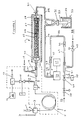
- a sample containing the element to be analyzed is dissolved in a solvent contained in syringe 1.
- the solution in syringe 1 is injected through septum 2 into an injector 3 where it mixes with a flow of helium carrier gas 4 and is carried on to a gas chromatographic column 5.
- Column 5 is preferably a capillary column disposed inside a conventional gas chromatographic oven schematically shown at 6.
- Injector 3 is preferably also heated, either by the column oven 6 or a separate oven (not shown).
- valve 10 is operated by a pneumatic actuator 13 located outside oven 6, and detector 11 is connected to a chart recorder or chromatograph data acquisition system 14.
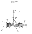
- capillary 16 which is typically made of the same type of tubing as column 5 (e.g, 0.20 mm bore quartz capillary tube). Capillary 16 extends right through make-up tee 12 and into the sample conversion means 17, and a second flow of carrier gas 18 is introduced into tee 12 through pipe 19.
- Capillary 16 is sealed into tee 12 by a graphitized ferrule 21 and secured by nut 22. Pipes 19 and 20 are sealed by conventional ferrules.
- Capillary 16 extends inside tube 20 so that the carrier gas entering through pipe 19 flows in the annular space between the exterior of capillary 16 and the inside wall of tube 20. This arrangement ensures turbulent mixing of the gases as they enter the sample conversion means 17.
- Pipe 20 and capillary 16 are heated between oven 6 and the conversion means 17 by means of a heating oven (not shown) which maintains their temperature at least as high as the column temperature, thereby preventing condensation of the sample.
- a heating oven (not shown) which maintains their temperature at least as high as the column temperature, thereby preventing condensation of the sample.
- Sample conversion means 17 comprises a quartz tube 23, of 1.0 mm inside diameter and 40 cm length, which is packed with a catalyst 24.
- Pipe 20 is connected to tube 23 by means of a reducing coupling 26, through which capillary 16 extends into catalyst 24, which is capable of converting the element present in the sample into an analysis gas (defined above).
- catalyst 24 may comprise cupric oxide or cobaltic oxide (CuO or Co3O4) granules of 0.3 - 0.4 mm diameter. These materials are capable of oxidizing substantially all the carbon present in an organic sample to carbon dioxide when maintained at 700-900°C. Tube 23 is heated by an electrically heated furance 27 which surrounds tube 23. Other catalysts may be used if desired.
- CuO or Co3O4 cupric oxide or cobaltic oxide
- conversion means 17 may be adapted for the catalytic oxidation of nitrogen contained within the sample to nitrogen oxides, which may be achieved with cupric or cobaltic oxide as described above. Under these conditions, the nitrogen oxides formed usually undergo thermal decomposition to produce sufficient nitrogen for an accurate isotopic ratio determination. However, if desired a second stage for the reduction of the nitrogen oxides to gaseous nitrogen may be provided. Metallic copper may be used for this. In practice, both catalysts can be packed into tube 23. Obviously the inlet end will be packed with copper oxide and the exit end with copper. Separate tubes may be employed if desired.
- An open split 30 is conveniently provided by ensuring that the inside diameter of coupling 28 is greater than the outside diameter of pipe 29, as shown.
- a small portion of the flow of analysis gas and carrier gas leaves tube 23 in pipe 29 and enters a coiled tube 33 in trapping means 32, which is adapted remove unwanted components such as water from the gas flow.
- Trapping means 32 comprises the coiled tube 33 in thermal contact with a thermally conductive bar 53. The other end of bar 53 is immersed in liquid nitrogen contained in an insulated vessel 34.
- the efficiency of the cooling of tube 33 is varied by means of a small electrical heater 31 mounted on bar 53, so that the temperature of tube 33 can be controlled by varying the power input to heater 31.
- the temperature should be maintained low enough to trap water but not carbon dioxide.
- the temperature of coiled tube 33 is reduced to condense carbon dioxide.
- additional chemical traps can be included.
- the outlet of trapping means 32 is taken via a restriction 36 to one inlet of a conventional multi-collector isotope-ratio spectrometer 35, which has two inlet ports and a computerized data acquisition system 37. Restriction 36 is selected to limit the flow into the spectrometer to about 0.2 - 0.5 ml/minute from atmospheric pressure (maintained by the splitting tee 30).
- Valve 10 is operated at times such that analysis gas enters the mass spectrometer during one or more second time intervals, and preferably so that effluent from the column 5 passes into the conversion means 17 for substantially all of the time that a sample is eluting. In conjunction with the integration procedure described below, this ensures that errors due to isotopic fractionation of the sample during the chromatographic separation are minimized. Valve 10 should also be closed as soon as possible after the peak has passed into conversion means 17 to ensure that interference with a subsequent calibration sample from column bleed or an unwanted component of the sample entering conversion means 17 is minimized.
- Figure 1 also illustrates a preferred means for introducing into the mass spectrometer during at least one first time interval a reference gas, such as a sample of carbon dioxide of accurately known isotopic composition.
- Reference gas flows in the direction of arrow 39 to pressure regulator 38 and a low-dead-volume valve 40 and through a capillary 42 into a second make-up tee 41.
- Tee 41 is of similar construction to tee 12, illustrated in figure 2.
- Capillary 42 extends from valve 40 through the tee 41 into a mixing volume provided by pipe 43, as shown in figure 1.
- Another flow of helium carrier gas 52 is supplied through regulator 45 into the side connection of the tee 41, which it leaves through the annular gap between the exterior of capillary 42 and the inside wall of mixing pipe 43.
- capillary 42 comprises a 150 mm length of 0.025 mm inside diameter quartz tube and pipe 43 comprises a 150 mm length of 0.5 mm bore stainless steel tube.
- the diameter of the capillary 42 is much smaller than capillary 16 because only a very small flow of calibration gas is required. Efficient mixing can only be achieved, however, if a restriction exists downstream of pipe 43, and this is provided by a 200 mm length of 0.15 mm bore stainless steel capillary tube 44, connected to pipe 43 by coupling 46.
- Tube 44 terminates in coupling 47 and a short length of 0.5 mm bore tube 48 into which capillary 50 (typically 0.075 mm inside diameter) is introduced as shown in figure 1 to form an open split 49.
- Capillary 50 which typically is 1750 mm long, is connected to the second inlet of the mass spectrometer 35. Open split 49 and capillary 50 ensure that spectrometer 35 receives a constant flow of carrier gas from this source, irrespective of changes made upstream of split 49.
- Calibration samples of reference gas are introduced during at least one first time interval simply by opening valve 40, which allows reference gas to enter the carrier gas flow into tee 41.
- the reference gas inlet comprising items 38-50 should have a very short response time which requires valve 40 to be of very low dead volume.
- valve 40 is operated by a pneumatic actuator 25. As explained, each first time interval is selected to be outside the or each second time interval, during which a sample of the analysis gas is present in the mass spectrometer.
- valves 10 and 40 has a very important effect on the performance of the system. They should start and stop the appropriate flows very quickly so that calibration samples and sample peaks can be introduced into the spectrometer in rapid succession and with minimum overlap.
- Micro needle valves of the type intended for use in gas chromatography in which the valve seat is integral with the ferrule sealing the outlet of the valve (for example type MOV from SGE Ltd) are suitable.
- capillary 42 is secured in a conventional capillary ferrule with expoxy resin so that the end of the tube is about 1 mm from the valve seat.
- Such valves have a very small dead volume on the outlet side when closed.
- a preferred method of operating the apparatus is as follows:- First, the interface system and a chromatographic column which will separate the components to be analyzed are conditioned in the normal way until a steady and small background signal is observed on the mass spectrometer. The sample is injected from syringe 1 on to the column 5 with valve 10 open so that column effluent is routed through the detector 11 and subsequently vented. Meanwhile, one or more calibration samples may be admitted into the mass spectrometer by opening valve 40. The isotopic composition of these is measured in a conventional way.
- valve 10 is closed to allow substantially all of the peak to pass into the conversion means 17 where it is converted to a gas (e.g, CO2 or N2) suitable for admission into the mass spectrometer.
- a gas e.g, CO2 or N2
- Selective trapping means 32 removes water and other unwanted material from the effluent of the conversion means, which is then admitted into the spectrometer.
- the isotopic ratio of the element under investigation is then determined by integrating with respect to time the outputs of the mass spectrometer which are indicative of at least two isotopes of the element. This should be carried out over the entire chromatographic peak to ensure that fractionation effects during the chromatograph separation or conversion do not adversely affect the measurement.
- valve 10 is closed and more calibration samples are admitted by opening valve 40.
- the isotopic composition of the sample is determined using the results of the calibration sample in a conventional way.
- sample in syringe 1 is a mixture
- other components eluting from the column may be analyzed during a single run, interspersing calibration samples between the peaks whenever possible. If the time between two peaks is too short to allow a calibration sample to be inserted, these peaks may be analyzed consecutively using calibration samples analyzed on either side of the pair.
- the whole apparatus is preferably automated and under the control of the computerized data acquisition system 37, which is also programmed to carry out the integration as discussed above.
- the acquisition system 37 may also conveniently be programmed to control valves 10 and 40, and also an automatic injector if available, to admit the sample to be analyzed and calibration samples according to the invention making due allowance for the time delays introduced by the column 5 and the conversion means 17, which are determined by previous experiments. Automation of the remainder of the system is conventional and need not be described in detail.
Landscapes
- Chemical & Material Sciences (AREA)
- Analytical Chemistry (AREA)
- Physics & Mathematics (AREA)
- Health & Medical Sciences (AREA)
- Life Sciences & Earth Sciences (AREA)
- Biochemistry (AREA)
- General Health & Medical Sciences (AREA)
- General Physics & Mathematics (AREA)
- Immunology (AREA)
- Pathology (AREA)
- Other Investigation Or Analysis Of Materials By Electrical Means (AREA)
Claims (12)
- un procédé pour déterminer la composition isotopique d'un élément compris dans un échantillon, ledit procédé comprenant :a) passage d'un gaz porteur à travers une colonne chromatographique de gaz et introduction dudit échantillon sur ladite colonne ;b) conversion d'au moins une partie dudit échantillon présent dans l'effluent provenant de ladite colonne en un gaz d'analyse, c'est-à-dire un gaz comprenant ledit élément sous forme élémentaire ou sous forme d'un composé simple, par exemple de l'azote ou du dioxyde de carbone ;c) introduction d'un ou de plusieurs échantillons d'étalonnage d'un gaz de référence contenant ledit élément dans un spectromètre de masse pendant au moins un premier intervalle de temps ;d) autorisation au gaz porteur qui est passé à travers ladite colonne de s'écouler dans ledit spectromètre de masse seulement pendant au moins un deuxième intervalle de temps, en dehors dudit ou de chacun desdits premiers intervalles de temps, une partie au moins dudit gaz d'analyse étant admis dans ledit spectromètre de masse pendant undit deuxième intervalle de temps ; ete) détermination de la composition isotopique dudit élément dans ledit gaz d'analyse à partir de sorties dudit spectromètre de masse indiquant ledit élément dans ledit gaz d'analyse et ledit gaz de référence.
- Un procédé selon la revendication 1, dans lequel seulement une partie de l'effluent provenant de la colonne chromatographique de gaz est introduite dans le spectromètre de masse pendant lesdits deuxièmes intervalles de temps et la partie restante est déchargée à une pression sensiblement constante, par exemple atmosphérique.
- Un procédé selon la revendication 2 dans lequel un deuxième flux d'un gaz porteur est ajouté à l'effluent provenant de ladite colonne avant la conversion dudit échantillon en ledit gaz d'analyse.
- Un procédé selon une quelconque revendication précédente dans lequel au moins l'un desdits seconds intervalles de temps est choisi de sorte qu'au moins une partie dudit effluent provenant de ladite colonne chromatographique est convertie en ledit gaz d'analyse pendant sensiblement tout le temps pendant lequel ledit échantillon est présent dans celle-ci, au moins une partie de l'effluent après conversion est passé dans ledit spectromètre de masse pendant sensiblement tout le temps pendant lequel ledit gaz d'analyse est présent dans celui-ci, et ladite composition isotopique est déterminée en partie par l'intégration des sorties dudit spectromètre de masse indiquant au moins deux isotopes dudit élément dans ledit gaz d'analyse pendant sensiblement tout le temps pendant lequel ledit gaz d'analyse entre dans ledit spectromètre de masse.
- Un procédé selon une quelconque revendication précédente dans lequel l'effluent provenant de ladite colonne chromatographique de gaz est passé dans un moyen pour convertir ledit échantillon en ledit gaz d'analyse seulement pendant le temps pendant lequel un échantillon dont la composition isotopique est à déterminer est en train de faire une élution dans ladite colonne chromatographique.
- Dispositif pour déterminer la composition isotopique d'un élément compris dans un échantillon, ledit dispositif comprenant :a) un spectromètre de masse pour proportion isotopique (35) adapté pour déterminer la composition isotopique d'un élément compris dans un gaz ;b) une colonne chromatographique de gaz (5) à travers laquelle un échantillon peut être passé ensemble avec un gaz porteur (4) ;c) un moyen de conversion d'échantillon (17) disposé pour recevoir au moins une partie de l'effluent de ladite colonne chromatographique (5) et agencé pour convertir ledit échantillon en un gaz d'analyse, c'est-à-dire un gaz comprenant ledit échantillon sous forme élémentaire ou sous la forme d'un composé simple, par exemple de l'azote ou du dioxyde de carbone ;d) un moyen (38-50) pour admettre dans ledit spectromètre de masse (35) pendant au moins un premier intervalle de temps un ou plusieurs échantillons d'étalonnage d'un gaz de référence (39) contenant ledit élément ; ete) un moyen pour autoriser le gaz porteur (4) qui est passé à travers ladite colonne (5) de s'écouler dans ledit spectromètre de masse (35) seulement pendant au moins un deuxième intervalle de temps, en dehors dudit ou de chacun desdits premiers intervalles de temps, une partie au moins dudit gaz d'analyse étant admis dans ledit spectromètre de masse (35) pendant undit deuxième intervalle de temps.
- Dispositif selon la revendication 6 comprenant en outre un moyen à fente ouverte (30) pour admettre seulement une portion choisie dudit effluent provenant de ladite colonne chromatographique de gaz (5) dans ledit spectromètre de masse (35) et un moyen pour décharger le reste (15) à une pression sensiblement constante, (par exemple atmosphérique).
- Dispositif selon la revendication 7 dans lequel ledit moyen à fente ouverte (30) est disposé en aval dudit moyen de conversion d'échantillon et comprenant en outre des moyens pour ajouter un deuxième flux (18) d'un gaz porteur à l'effluent de ladite colonne chromatographique (35) à l'entrée dudit moyen de conversion d'échantillon (17).
- Dispositif selon l'une quelconque des revendications 6 à 8 dans lequel ledit moyen (7, 10) pour admettre dans ledit spectromètre de masse (35) pendant au moins un deuxième intervalle de temps est en outre adapté pour permettre à l'effluent provenant de ladite colonne chromatographique (5) de passer dans ledit moyen de conversion d'échantillon (17) seulement pendant la période pendant laquelle ledit échantillon fait une élution dans ladite colonne chromatographique (5).
- Dispositif selon l'une quelconque des revendications 6 à 9 dans lequel ledit moyen (7, 10) pour admettre dans ledit spectromètre de masse pendant au moins un deuxième intervalle de temps est en outre adapté de sorte qu'au moins une partie de l'effluent provenant de ladite colonne chromatographique (5) est passée dans ledit moyen de conversion d'échantillon (17) pendant sensiblement tout le temps pendant lequel ledit échantillon est présent dans celui-ci, au moins une partie de l'effluent provenant dudit moyen de conversion d'échantillon (17) est passé dans ledit spectromètre de masse (35) pendant sensiblement tout le temps pendant lequel ledit gaz d'analyse est présent dans celui-ci, et des moyens (37) sont fournis pour intégrer en fonction du temps les sorties dudit spectromètre de masse (35) indiquant au moins deux isotopes dudit élément pendant sensiblement tout le temps pendant lequel ledit gaz d'analyse entre dans ledit spectromètre de masse (35).
- Dispositif selon l'une quelconque des revendications 6 à 10 dans lequel ledit élément comprend du carbone et ledit gaz d'analyse et ledit gaz de référence comprennent du dioxyde de carbone.
- Dispositif selon l'une quelconque des revendications 6 à 11 dans lequel un moyen purgeur (32) est disposé entre ledit moyen de conversion d'échantillon (17) et ledit spectromètre de masse (35) pour retirer l'eau et les autres impuretés condensables de l'effluent provenant dudit moyen de conversion d'échantillon (17).
Applications Claiming Priority (2)
| Application Number | Priority Date | Filing Date | Title |
|---|---|---|---|
| GB878720586A GB8720586D0 (en) | 1987-09-02 | 1987-09-02 | Apparatus & method |
| GB8720586 | 1987-09-02 |
Publications (3)
| Publication Number | Publication Date |
|---|---|
| EP0306332A2 EP0306332A2 (fr) | 1989-03-08 |
| EP0306332A3 EP0306332A3 (en) | 1990-01-31 |
| EP0306332B1 true EP0306332B1 (fr) | 1992-12-09 |
Family
ID=10623129
Family Applications (1)
| Application Number | Title | Priority Date | Filing Date |
|---|---|---|---|
| EP88308155A Expired - Lifetime EP0306332B1 (fr) | 1987-09-02 | 1988-09-02 | Procédé et dispositif pour déterminer une composition d'isotopes |
Country Status (5)
| Country | Link |
|---|---|
| US (1) | US4916313A (fr) |
| EP (1) | EP0306332B1 (fr) |
| JP (1) | JP2934879B2 (fr) |
| DE (1) | DE3876545T2 (fr) |
| GB (2) | GB8720586D0 (fr) |
Cited By (3)
| Publication number | Priority date | Publication date | Assignee | Title |
|---|---|---|---|---|
| US7213443B2 (en) | 2002-04-16 | 2007-05-08 | University Of Bern | Process and apparatus for providing gas for isotopic ratio analysis |
| DE10256009B4 (de) * | 2002-04-16 | 2008-05-29 | Universitaet Bern | Verfahren und Vorrichtung zur Bereitstellung einer gasförmigen Substanz für die Analyse von chemischen Elementen oder Verbindungen |
| US7985597B2 (en) | 2002-04-16 | 2011-07-26 | Universitat Bern | Process and apparatus for providing a gaseous substance for the analysis of chemical elements or compounds |
Families Citing this family (26)
| Publication number | Priority date | Publication date | Assignee | Title |
|---|---|---|---|---|
| GB8921285D0 (en) * | 1989-09-20 | 1989-11-08 | Vg Instr Group | Isotopic composition analyzer |
| CA2037862C (fr) * | 1990-03-12 | 2002-09-17 | David P. Rounbehler | Mode de detection rapide de vapeur, avec mise en derivation |
| IT1252088B (it) * | 1991-10-25 | 1995-06-01 | Erba Strumentazione | Apparecchiatura e procedimento di analisi o-fid |
| US5431821A (en) * | 1992-02-07 | 1995-07-11 | The Ohio State University | Glassy carbon in separation processes |
| GB2270977B (en) * | 1992-09-26 | 1996-06-12 | Finnigan Mat Gmbh | Combustion oven for the oxidation of components in organic samples, and process therefor |
| US5424539A (en) * | 1992-12-18 | 1995-06-13 | Finnegan Mat Gmbh | Process for the analysis of gaseous components by mass spectrometry |
| US5378895A (en) * | 1993-11-12 | 1995-01-03 | Eg&G Idaho, Inc. | Gamma neutron assay method and apparatus |
| GB9418638D0 (en) * | 1994-09-15 | 1994-11-02 | Fisons Plc | Isotopic composition analyser |
| DE4437120C2 (de) * | 1994-10-05 | 1998-02-12 | Ufz Leipzighalle Gmbh | Verfahren und Vorrichtung zur on-line gekoppelten Deuteriumbestimmung |
| US5672404A (en) * | 1995-09-07 | 1997-09-30 | Minnesota Mining And Manufacturing Company | Attachment strips |
| US5703360A (en) * | 1996-08-30 | 1997-12-30 | Hewlett-Packard Company | Automated calibrant system for use in a liquid separation/mass spectrometry apparatus |
| US5783741A (en) * | 1997-01-31 | 1998-07-21 | Atlantic Richfield Company | Capillary furnace for improved peak resolution in gas isotope chromatography |
| US20030165212A1 (en) * | 1998-02-18 | 2003-09-04 | Maglich Bogdan C. | Method and apparatus for detecting, locating, and analyzing chemical compounds using subatomic particle activation |
| DE19956632C1 (de) * | 1999-11-25 | 2001-06-28 | Finnigan Mat Gmbh | Verfahren und Vorrichtung zur Herstellung von Standardgasen für die Bestimmung von Isotopenverhältnissen |
| US6944549B2 (en) * | 2002-10-25 | 2005-09-13 | Syngenta Participations Ag | Method and apparatus for automated detection of peaks in spectroscopic data |
| WO2005015165A1 (fr) * | 2003-05-23 | 2005-02-17 | Perkinelmer Las, Inc. | Procede de verification de l'integrite de tubes d'echantillonnage de desorption thermique |
| US20050254614A1 (en) * | 2004-03-11 | 2005-11-17 | Mckinny Kevin S | Method and apparatus for measuring wall thickness of a vessel |
| US7211793B2 (en) * | 2004-11-09 | 2007-05-01 | Cummins, Inc | Mass spectrometry system and method |
| US7928369B2 (en) * | 2006-03-31 | 2011-04-19 | Thermo Fisher Scientific (Bremen) Gmbh | Device for the analysis of isotope ratios |
| DE102006015535A1 (de) * | 2006-03-31 | 2007-10-04 | Thermo Electron (Bremen) Gmbh | Verfahren und Vorrichtung zur Analyse von Isotopenverhältnissen |
| DE102007031680A1 (de) * | 2007-07-06 | 2009-01-08 | Thermo Fisher Scientific (Bremen) Gmbh | Einrichtung zur Bereitstellung von Gasen, insbesondere für die Isotopenverhältnisanalyse |
| DE102008016583A1 (de) * | 2008-03-31 | 2009-10-01 | Thermo Fisher Scientific (Bremen) Gmbh | Vorrichtung und Verfahren zur Bildung von CO2, N2 und/oder SO2 aus einer Probe |
| CN105122053B (zh) * | 2013-04-15 | 2018-11-30 | 塞莫费雪科学(不来梅)有限公司 | 用于同位素比分析仪的进气系统和确定同位素比的方法 |
| EP3397956B1 (fr) * | 2015-12-29 | 2019-10-30 | Total Raffinage Chimie | Procédé de détection et de quantification d'oxygène dans des composés oxydables |
| JP6348193B1 (ja) * | 2017-02-06 | 2018-06-27 | 日清食品ホールディングス株式会社 | アミノ酸の由来判別方法 |
| CN113167732B (zh) * | 2018-12-12 | 2025-01-28 | 株式会社岛津制作所 | 硫化学发光检测器 |
Family Cites Families (4)
| Publication number | Priority date | Publication date | Assignee | Title |
|---|---|---|---|---|
| US3712111A (en) * | 1968-07-10 | 1973-01-23 | Vanan Ass | Flow control for gas analyzing apparatus |
| JPS6050301B2 (ja) * | 1977-12-29 | 1985-11-07 | 株式会社島津製作所 | クロマトグラフ質量分析装置 |
| US4467038A (en) * | 1981-11-30 | 1984-08-21 | Phillips Petroleum Company | Predetector reservoir for chromatographic analysis instrument |
| US4641541A (en) * | 1986-02-11 | 1987-02-10 | Daryl Sharp | Internal mass spectrometer interface to a gas chromatograph |
-
1987
- 1987-09-02 GB GB878720586A patent/GB8720586D0/en active Pending
-
1988
- 1988-05-13 GB GB888811379A patent/GB8811379D0/en active Pending
- 1988-08-31 US US07/238,910 patent/US4916313A/en not_active Expired - Lifetime
- 1988-09-02 JP JP63220299A patent/JP2934879B2/ja not_active Expired - Lifetime
- 1988-09-02 EP EP88308155A patent/EP0306332B1/fr not_active Expired - Lifetime
- 1988-09-02 DE DE8888308155T patent/DE3876545T2/de not_active Expired - Lifetime
Cited By (3)
| Publication number | Priority date | Publication date | Assignee | Title |
|---|---|---|---|---|
| US7213443B2 (en) | 2002-04-16 | 2007-05-08 | University Of Bern | Process and apparatus for providing gas for isotopic ratio analysis |
| DE10256009B4 (de) * | 2002-04-16 | 2008-05-29 | Universitaet Bern | Verfahren und Vorrichtung zur Bereitstellung einer gasförmigen Substanz für die Analyse von chemischen Elementen oder Verbindungen |
| US7985597B2 (en) | 2002-04-16 | 2011-07-26 | Universitat Bern | Process and apparatus for providing a gaseous substance for the analysis of chemical elements or compounds |
Also Published As
| Publication number | Publication date |
|---|---|
| GB8720586D0 (en) | 1987-10-07 |
| JP2934879B2 (ja) | 1999-08-16 |
| EP0306332A2 (fr) | 1989-03-08 |
| JPH01127955A (ja) | 1989-05-19 |
| US4916313A (en) | 1990-04-10 |
| DE3876545D1 (de) | 1993-01-21 |
| GB8811379D0 (en) | 1988-06-15 |
| DE3876545T2 (de) | 1993-04-15 |
| EP0306332A3 (en) | 1990-01-31 |
Similar Documents
| Publication | Publication Date | Title |
|---|---|---|
| US4916313A (en) | Method and apparatus for the determination of isotopic composition | |
| EP0306333B1 (fr) | Procédé et dispositif pour déterminer une composition d'isotopes | |
| US5766954A (en) | Isotopic composition analyser | |
| US5314827A (en) | Isotopic composition analyzer | |
| US8448493B2 (en) | Gas chromatograph-combustion system and method for mass spectrometry | |
| US5281397A (en) | Adjustable open-split interface for a gas chromatograph and a mass spectrometer | |
| Schomburg et al. | Aspects of double-column gas chromatography with glass capillaries involving intermediate trapping | |
| US5288310A (en) | Adsorbent trap for gas chromatography | |
| EP0661537B1 (fr) | Dispositif pour la chromatochraphie en phase gazeuse | |
| US6834531B2 (en) | Gas chromatograph modular auxiliary oven assembly and method for analyzing a refinery gas | |
| US4359891A (en) | Repetitive chromatographic apparatus | |
| US5432344A (en) | Appliance for the oxidation of components in organic samples, and process therefor | |
| CN108414633A (zh) | 一种微量氮同位素的测定仪器及其应用 | |
| US5108468A (en) | Switching system for a multidimensional gas chromatograph | |
| US5596876A (en) | Miniaturized cryogenic trap apparatus | |
| US3735565A (en) | Enrichment of chromatograph output | |
| JPS61213655A (ja) | ガスクロマトグラフと質量分析計を備えた熱分析装置 | |
| US5498279A (en) | High speed gas chromatography system for analysis of polar organic compounds | |
| EP0654667A1 (fr) | Systèmes de chromatographie en phase gazeuse | |
| US3728845A (en) | Method and apparatus for stripping the components of a mixed sample from a trap | |
| Kiran et al. | Pyrolysis–molecular weight chromatography–vapor‐phase infrared spectrophotometry: A new on‐line system for analysis of polymers. I. Instrumentation | |
| GB2370517A (en) | Gas chromatography-mass spectrometer having different length chromatography columns | |
| RU1803861C (ru) | Способ термокондуктометрического детектировани газов в хроматографии | |
| SU935784A1 (ru) | Газовый хроматограф | |
| Kern et al. | Precision of an automated all‐glass capillary gas chromatography system with an electron capture detector for the trace analysis of estrogens |
Legal Events
| Date | Code | Title | Description |
|---|---|---|---|
| PUAI | Public reference made under article 153(3) epc to a published international application that has entered the european phase |
Free format text: ORIGINAL CODE: 0009012 |
|
| AK | Designated contracting states |
Kind code of ref document: A2 Designated state(s): DE FR GB IT NL |
|
| PUAL | Search report despatched |
Free format text: ORIGINAL CODE: 0009013 |
|
| AK | Designated contracting states |
Kind code of ref document: A3 Designated state(s): DE FR GB IT NL |
|
| 17P | Request for examination filed |
Effective date: 19900320 |
|
| 17Q | First examination report despatched |
Effective date: 19911021 |
|
| RAP1 | Party data changed (applicant data changed or rights of an application transferred) |
Owner name: FISONS PLC |
|
| GRAA | (expected) grant |
Free format text: ORIGINAL CODE: 0009210 |
|
| ITF | It: translation for a ep patent filed | ||
| AK | Designated contracting states |
Kind code of ref document: B1 Designated state(s): DE FR GB IT NL |
|
| ET | Fr: translation filed | ||
| REF | Corresponds to: |
Ref document number: 3876545 Country of ref document: DE Date of ref document: 19930121 |
|
| PLBE | No opposition filed within time limit |
Free format text: ORIGINAL CODE: 0009261 |
|
| STAA | Information on the status of an ep patent application or granted ep patent |
Free format text: STATUS: NO OPPOSITION FILED WITHIN TIME LIMIT |
|
| 26N | No opposition filed | ||
| NLS | Nl: assignments of ep-patents |
Owner name: MICROMASS LIMITED |
|
| REG | Reference to a national code |
Ref country code: FR Ref legal event code: TP |
|
| REG | Reference to a national code |
Ref country code: GB Ref legal event code: 732E |
|
| REG | Reference to a national code |
Ref country code: GB Ref legal event code: 732E |
|
| REG | Reference to a national code |
Ref country code: FR Ref legal event code: CA |
|
| REG | Reference to a national code |
Ref country code: GB Ref legal event code: IF02 |
|
| REG | Reference to a national code |
Ref country code: GB Ref legal event code: 732E |
|
| NLS | Nl: assignments of ep-patents |
Owner name: MICROMASS UK LIMITED |
|
| PGFP | Annual fee paid to national office [announced via postgrant information from national office to epo] |
Ref country code: GB Payment date: 20070926 Year of fee payment: 20 |
|
| PGFP | Annual fee paid to national office [announced via postgrant information from national office to epo] |
Ref country code: IT Payment date: 20070927 Year of fee payment: 20 Ref country code: NL Payment date: 20070923 Year of fee payment: 20 Ref country code: DE Payment date: 20071031 Year of fee payment: 20 |
|
| PGFP | Annual fee paid to national office [announced via postgrant information from national office to epo] |
Ref country code: FR Payment date: 20070917 Year of fee payment: 20 |
|
| REG | Reference to a national code |
Ref country code: GB Ref legal event code: PE20 Expiry date: 20080901 |
|
| NLV7 | Nl: ceased due to reaching the maximum lifetime of a patent |
Effective date: 20080902 |
|
| PG25 | Lapsed in a contracting state [announced via postgrant information from national office to epo] |
Ref country code: NL Free format text: LAPSE BECAUSE OF EXPIRATION OF PROTECTION Effective date: 20080902 |
|
| PG25 | Lapsed in a contracting state [announced via postgrant information from national office to epo] |
Ref country code: GB Free format text: LAPSE BECAUSE OF EXPIRATION OF PROTECTION Effective date: 20080901 |