EP0307062A2 - Machine automatique à fabriquer des cadres par pliage de barres ou bandes en acier et procédé et appareil pour la fabrication de noyaux de ressorts pour des matelas ou des meubles de capilonnage - Google Patents
Machine automatique à fabriquer des cadres par pliage de barres ou bandes en acier et procédé et appareil pour la fabrication de noyaux de ressorts pour des matelas ou des meubles de capilonnage Download PDFInfo
- Publication number
- EP0307062A2 EP0307062A2 EP88202057A EP88202057A EP0307062A2 EP 0307062 A2 EP0307062 A2 EP 0307062A2 EP 88202057 A EP88202057 A EP 88202057A EP 88202057 A EP88202057 A EP 88202057A EP 0307062 A2 EP0307062 A2 EP 0307062A2
- Authority
- EP
- European Patent Office
- Prior art keywords
- frame
- bending
- bending machine
- spring core
- round
- Prior art date
- Legal status (The legal status is an assumption and is not a legal conclusion. Google has not performed a legal analysis and makes no representation as to the accuracy of the status listed.)
- Withdrawn
Links
Images

Classifications
-
- B—PERFORMING OPERATIONS; TRANSPORTING
- B21—MECHANICAL METAL-WORKING WITHOUT ESSENTIALLY REMOVING MATERIAL; PUNCHING METAL
- B21F—WORKING OR PROCESSING OF METAL WIRE
- B21F33/00—Tools or devices specially designed for handling or processing wire fabrics or the like
- B21F33/02—Mounting of wire network on frames
- B21F33/025—Mounting of mattress innersprings on borderframes
-
- B—PERFORMING OPERATIONS; TRANSPORTING
- B21—MECHANICAL METAL-WORKING WITHOUT ESSENTIALLY REMOVING MATERIAL; PUNCHING METAL
- B21D—WORKING OR PROCESSING OF SHEET METAL OR METAL TUBES, RODS OR PROFILES WITHOUT ESSENTIALLY REMOVING MATERIAL; PUNCHING METAL
- B21D7/00—Bending rods, profiles, or tubes
- B21D7/02—Bending rods, profiles, or tubes over a stationary forming member; by use of a swinging forming member or abutment
- B21D7/022—Bending rods, profiles, or tubes over a stationary forming member; by use of a swinging forming member or abutment over a stationary forming member only
-
- B—PERFORMING OPERATIONS; TRANSPORTING
- B21—MECHANICAL METAL-WORKING WITHOUT ESSENTIALLY REMOVING MATERIAL; PUNCHING METAL
- B21F—WORKING OR PROCESSING OF METAL WIRE
- B21F1/00—Bending wire other than coiling; Straightening wire
-
- B—PERFORMING OPERATIONS; TRANSPORTING
- B21—MECHANICAL METAL-WORKING WITHOUT ESSENTIALLY REMOVING MATERIAL; PUNCHING METAL
- B21F—WORKING OR PROCESSING OF METAL WIRE
- B21F33/00—Tools or devices specially designed for handling or processing wire fabrics or the like
- B21F33/02—Mounting of wire network on frames
-
- Y—GENERAL TAGGING OF NEW TECHNOLOGICAL DEVELOPMENTS; GENERAL TAGGING OF CROSS-SECTIONAL TECHNOLOGIES SPANNING OVER SEVERAL SECTIONS OF THE IPC; TECHNICAL SUBJECTS COVERED BY FORMER USPC CROSS-REFERENCE ART COLLECTIONS [XRACs] AND DIGESTS
- Y10—TECHNICAL SUBJECTS COVERED BY FORMER USPC
- Y10T—TECHNICAL SUBJECTS COVERED BY FORMER US CLASSIFICATION
- Y10T29/00—Metal working
- Y10T29/48—Upholstered article making
-
- Y—GENERAL TAGGING OF NEW TECHNOLOGICAL DEVELOPMENTS; GENERAL TAGGING OF CROSS-SECTIONAL TECHNOLOGIES SPANNING OVER SEVERAL SECTIONS OF THE IPC; TECHNICAL SUBJECTS COVERED BY FORMER USPC CROSS-REFERENCE ART COLLECTIONS [XRACs] AND DIGESTS
- Y10—TECHNICAL SUBJECTS COVERED BY FORMER USPC
- Y10T—TECHNICAL SUBJECTS COVERED BY FORMER US CLASSIFICATION
- Y10T29/00—Metal working
- Y10T29/48—Upholstered article making
- Y10T29/481—Method
-
- Y—GENERAL TAGGING OF NEW TECHNOLOGICAL DEVELOPMENTS; GENERAL TAGGING OF CROSS-SECTIONAL TECHNOLOGIES SPANNING OVER SEVERAL SECTIONS OF THE IPC; TECHNICAL SUBJECTS COVERED BY FORMER USPC CROSS-REFERENCE ART COLLECTIONS [XRACs] AND DIGESTS
- Y10—TECHNICAL SUBJECTS COVERED BY FORMER USPC
- Y10T—TECHNICAL SUBJECTS COVERED BY FORMER US CLASSIFICATION
- Y10T29/00—Metal working
- Y10T29/53—Means to assemble or disassemble
- Y10T29/53313—Means to interrelatedly feed plural work parts from plural sources without manual intervention
-
- Y—GENERAL TAGGING OF NEW TECHNOLOGICAL DEVELOPMENTS; GENERAL TAGGING OF CROSS-SECTIONAL TECHNOLOGIES SPANNING OVER SEVERAL SECTIONS OF THE IPC; TECHNICAL SUBJECTS COVERED BY FORMER USPC CROSS-REFERENCE ART COLLECTIONS [XRACs] AND DIGESTS
- Y10—TECHNICAL SUBJECTS COVERED BY FORMER USPC
- Y10T—TECHNICAL SUBJECTS COVERED BY FORMER US CLASSIFICATION
- Y10T29/00—Metal working
- Y10T29/53—Means to assemble or disassemble
- Y10T29/53313—Means to interrelatedly feed plural work parts from plural sources without manual intervention
- Y10T29/53383—Means to interrelatedly feed plural work parts from plural sources without manual intervention and means to fasten work parts together
Definitions
- the invention relates to an automatic frame bending machine for bending round or strip steel and a method and device for producing spring cores for mattresses or upholstered furniture.
- the object of the present invention is to design a frame bending machine in such a way that frames of the most varied types can be produced automatically in a structurally simple manner without the risk of material loss or the risk of the frames being distorted.
- the frame bending machine should be easy to integrate into a production line for the production of spring cores for mattresses or upholstered furniture.
- the essence of the invention lies in the special combination of Individual units in the manner of a series or series connection in connection with the microprocessor control and the hydraulic unit, the individual units being coordinated with one another and arranged in the plane of the round or strip steel.
- the pulling rollers pull the round steel to be straightened through the rollers of the wire straightening apparatus, the rotor arranging the angles of the frame to be bent in one plane by rotating the round or strip steel.
- the bending device consists of a pin which can be pivoted about a fixed axis, the round or strip steel to be bent running between the axis and the pin.
- the pin is driven on a swivel arm by a hydraulic motor with which a high degree of accuracy is achieved, starting from the start to the end area.
- the bending device consists of a center disk and a bending roller, the center disk having a circumferential groove for receiving the round or strip steel to be bent, and the bending roller is guided along the outer circumference of the center disk in the region of a swivel arm according to the angle to be bent.
- the cutting device is provided in the area of deflectors in the extension of the bending device against the direction of movement of the bending device, the round or strip steel to be cut running in a counter bearing.
- the centering plate is advantageously semicircularly arched at the end of the frame bending machine.
- the invention also relates to a method for producing spring cores for mattresses or upholstered furniture, a spring core being provided which is provided with a frame on the top and bottom.
- the previously known methods and devices still require some additionally a relatively large amount of manual work, especially in the processing area, in order to connect the spring core to the frame parts.
- the known devices and methods in particular do not allow rapid, cyclical work.
- the essence of the method lies in the fact that the frames are produced and put down pointing in one direction, and that a spring core is put on in another direction. The removal then takes place in a further direction. Accordingly, a rapid processing cycle takes place in such a way that individual method steps for producing the spring mattress are arranged in the directions perpendicular to one another.
- An advantageous embodiment of the method provides that two frames are provided for production at the same time for a faster cycle, a first frame being placed on the clamp table and clamped with a first spring core on the underside, and the first spring core with the first frame in the waiting position is moved in one direction, that a second spring core is clamped with a second frame on the clamp table and is moved in the waiting position in another direction, that the first spring core is turned and moved back and is clamped and transported on the clamp table with a third frame, and that the second innerspring turned and moved back and is clamped and removed on the clamp table with another fourth frame.
- a particularly rapid cycle can be achieved here in that the partially finished spring mattresses are moved back and forth in the area of the processing station in the manner of a waiting position, with a new frame always being placed and processed. In this way, two spring mattresses can always be produced and ejected at the same time.
- the device for producing spring mattresses relates to a spring core, which is provided with a frame on the top and bottom and in particular provides that a frame bending machine is provided in one direction at the beginning of a production line and a butt welding device or a clamp device, and in the further a feed unit with stacked arrangement of the frames and a further feed device to a staple table in a processing station, a turning and transport device being provided above the staple table that a transport device for spring cores is provided in relation to the staple table from another direction, that at the staple table four clamp heads are arranged, and that an additional table is provided in a further direction for removal via the turning and transport device.
- the essence of the device is to first provide the processing and feeding stations for the manufacture of the frames in one direction of the production line.
- the actual processing station is arranged in a different direction, the actual processing on the clamp table taking place approximately in the middle of the processing station at the end of the Delivery for the frames.
- the entire spring mattress can be manufactured on a single table, here on the clamp table, with long delivery routes being avoided in view of a fast cycle time.
- the production line is provided in a T-shape with the bending station at one end, with feeding and depositing of the frames in one direction, and the arrangement of the processing station in another direction perpendicular to it, the processing station being the clamping table with the clamping heads and contains the turning and transporting device in the middle as well as the transporting device for spring cores and the transporting device for the removal.
- the frame production and storage is provided in one direction, while the processing station is arranged perpendicular to it.
- the processing station is arranged perpendicular to it.
- the automatic frame bending machine 14 consists of a reel 13 connected upstream of the machine, from where the wire 3, in particular round steel, runs into a wire straightening device 2a or is drawn in by pulling rollers 5, a wire straightening device not being necessary when using steel strip .
- the traction rollers 5, which are arranged in pairs, are preceded in pairs by measuring rollers 4 without their own drive in order to determine the incoming wire with millimeter accuracy, which is cut off by the cutting device 9 after the bending process.
- the bending device 6 consists of a fixed axis 7, around which a pin 8 is pivoted by means of a pivot arm which is driven hydraulically thus angling the wire or strip material when pivoting the pin 8.
- the axis 7 and the pin 8 can also be provided with suitable grooves.
- the cutting device 9 is connected to the bending device 6, in particular with a fixed counter bearing 10, which also serves as a tape guide.
- the finished bent parts are intercepted by a centering plate 11 and centered and bent upwards so as to limit the length of the machine with full effect.
- the machine itself in particular the drive and bending units and also the wire straightening device and the measuring rollers, are controlled by an operating unit 12 on a microprocessor basis.
- the wire or the strip steel is aligned so that the frame is flat and true to the angle after the bending process without the need for reworking.
- the wire straightening apparatus 2 a works without wear, in particular without friction of the wire or the strip steel, with a particularly simple and precise alignment of the wire material taking place in connection with a twisting of the wire to be straightened via the rotor 1.
- the measuring rollers 4 consist of a pair of roles for the electronic measurement of the length of the drawn or advanced wire can be used.
- the measurement is done with an electronic pulse generator, the axis of which is connected to the shaft of one of the rollers.
- the second pair of rollers serves as pulling rollers 5 and pulls or drives the wire or the strip material in order to determine the lengths required for the frame production.
- the tension rollers 5 brake the material with millimeter accuracy when the necessary length is reached, so that the corresponding bends can take place in such an exact manner.
- the drive rollers 5 are driven by a hydraulic motor which is controlled by the control unit 12.
- two speeds are used, the slower speed being achieved by throttling the corresponding oil throughput.
- the lower speed is used to run through the last centimeter of any length. In this way, the inertia of the device is greatly reduced and a measurement accurate to the millimeter is achieved in connection with a feed.
- the bending device 6 is also driven by a hydraulic motor, a high degree of accuracy being achieved starting from the beginning to the end region or at a standstill.
- the cutting device 9 is also carried out by a hydraulic cutter, the counter bearing 10 of the cutting device 9 being arranged such that the wire passes through this guide device after being bent, so that on the one hand a continuous wire is not hindered and on the other hand can be cut very precisely .
- the semicircular plate or the centering plate 11 limits the spread of the finished frame, the finished frame being bent elastically without permanent deformation taking place. In this way it is possible to set up the frame bending machine in a very small space.
- the frame bending machine is programmed electronically via the control unit 12. In particular, it is provided to program and control the wire straightening apparatus 2a, the pulling rollers 5 and the measuring rollers 4, and the bending device 6 and the cutting device 9, all activities being carried out automatically.
- the wire 3 or the round or strip steel is unwound from the reel 13 and passes through the rotating rotor 1 in a straight line, the pull rollers 5 and the measuring rollers 4 determining the length of each side of a frame. Before the corresponding length is reached, the feed speed is reduced so that the inertia is limited and accuracy of the wire processing is achieved in the millimeter range.
- the wire After the wire 3 has stopped, the wire is bent in the bending device 6 to the desired angle.
- the arm then swings Beige device returns to the basic position, the wire is advanced and the bending process is repeated until the programmed shape is reached.
- the cutting device 9 cuts off the wire and the process with the passage of the wire, controlled by the operating unit 12, begins anew.
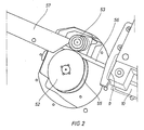
- FIG. 2 Another embodiment of the bending device 6 is shown in FIG. 2, the round or strip steel to be bent being bent around a disk.
- a fixed roller or a center disk 52 is provided, in which a groove 55 for receiving the round or strip steel is incorporated.
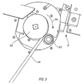
- the round or strip steel to be bent runs in the groove 55 and is bent by a bending roller 53, the bending roller 53 resting on top of the center disk 52 and then pivoted in the direction of arrow 54 according to FIG. 3 or the turning roller 53 moves around the fixed center disk 52 around and bends the round or strip steel in the desired angular range.
- FIG. 3 shows how the bending roller 53 is guided around the circumference of the center disk 52, advantageously by means of a swivel arm, in order to bend the round or strip steel in this way.
- the cutting device 9 with the counter bearing 10 can be seen, which is arranged exactly in the extension of a band guide 57 for the round or band steel, so that the material is also such after a turning process always runs in the counter bearing 10 and can easily be cut off there by the hydraulically moved scissors above the round or strip steel.
- the round or strip steel is always captured or captured in the counter bearing 10 even after the bending process in connection with the strip guide 57, so that the trouble-free operation of the frame bending machine is ensured in this way.
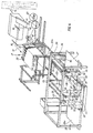
- FIG. 4 shows how the frame bending machine according to the invention is integrated in an automatic production line.
- the bending machine 14 at the beginning of the production line is controlled by certain process parameters from the operating unit 12, it being possible to generate any profiles with bends.
- the microprocessor control of the frame bending machine in connection with the operating unit 12 can be used to generate, in particular, rectangular or arcuate profiles in the manner of frames, which either overlap at the joints or the joints are arranged bluntly to one another.
- triangular profiles can also be bent.
- the frame bending machine can also use two frames at the same time, i. H. be bent in an overlying arrangement so that a faster manufacturing process is achieved in this way.
- the strip steel is provided with two wires, in contrast to single-wire strip steel or round steel.
- the frame bending machine 14 comprises in particular the electronic control on a microprocessor basis, so that simple program input can be achieved by means of dialogue (12 seconds), up to 100 different frame shapes being storable and retrievable by means of a code number (approx. 3 seconds).
- the special wire straightening device 2a prevents the frames from being deformed, with wear-free working being achieved here. In this way, material loss through adjustment attempts is avoided, i.e. the correct shape is achieved from the first frame.
- the frame bending machine 14 according to FIG. 4 can be easily integrated or linked to a production line in such a way that automation of the spring core production can be easily achieved here.
- the frame bending machine 14 can be easily installed and in particular, no conversion effort for other frame shapes is necessary. ie only the entry via a new code number is changed at the push of a button in order to be able to produce other frame shapes.
- a hydraulic unit is advantageously already integrated in the frame bending machine, so that a compact design is achieved in this way.
- the finished frame 15 is transported away from the bending machine 14 by two feeders 16 in the direction of arrow 17 from the frame bending machine 14.
- the frame 15 is transported to a butt welding device 18, where the frame joint 19 is either welded to the butt welding machine 18 or where a clamp 20 is placed on the frame joint 19, which closes the frame joint 19 completely and thus closes the frame .
- the completely connected frame 15 is fed to a feed unit 21, where a plurality of frames 15, 15a, 15b, 15c can be stacked on corresponding supports 22.
- the frame next to it is only used if you want to process two finished frame sizes without using a bending machine.
- the two feed units 21 and the further feed unit standing to the left of the feed unit 21 would then move back and forth on the rails, in order then to come to a comparison with the further processing device.
- the feed unit 21 is essential, on which frames, 15, 15a, 15b, 15c of different sizes are stacked.
- the frame 15 pointing in the processing direction requested by the subsequent machine is removed via a feed device 22a, with carriers 23 engaging in the feed unit 21 and picking up the requested frame there.
- This feed unit 22a is moved in the direction of arrow 24 on the rails 25 and the requested frame reaches a processing station 26 arranged in the vertical direction.
- the processing station initially consists of a centering and feed table 27, a clamp table 28 and a table 28a as a discharge station.
- the processing station 26 also consists of a turning and transport device 29 and four clamp heads 30, 31, 32, 32a, the fourth clamp head 32a, which is located on the rear one, not being visible left corner of the bracket table 28 is arranged.
- the frame 15, 15a, 15b, 15c is first placed horizontally on the clamp table 28 by the feed device 22a via the rails 25.
- each underside of each spring is first connected to the frame abutting it by means of clamps, then the entire spring core clamped at the bottom is turned over with the turning device 29, and all the undersides of the springs are then clamped together again.
- the finished innerspring is then transported onto the table 28a and transported away in the direction of the arrow 33.
- a conveyor belt can also be used, where the finished innerspring mattresses are removed.
- the spring cores without a frame are placed on the centering and feed table 27, the table 27 having stops, not shown, against which the spring core is aligned. After alignment, the spring core is gripped by the transport device 34, this transport device having clamp jaws 35 and the transport device 34 being movable in the direction of arrow 36 on the main frame 38 of the device.
- the spring cores detected by the device 34 are thus brought onto the clamp table 28, where the frame 15 has already been inserted.
- each spring 40 being clamped on its underside 41 to the corresponding frame 15 a via a clamp.
- Each clip head can be moved in one side, the clip head 31 being movable in the arrow direction 42, the clip head 30 in the arrow direction 43, the clip head 32 in the arrow direction 44 and the clip head 32a counter to the arrow direction 42.
- the turning device 29 comes into operation, turns the entire mattress over and the clamp heads now connect the upper sides 46 of the springs 40 (which now lie below) with the corresponding clamps other frame 15b.
- the mattress is placed on the dispensing table 28a in the direction of arrow 49 by moving the turning and transport device 29 and a new spring core is placed on the clamp table 28 via the transport device 34, previously a further frame 15c has been placed on the table by the feed station 22a.
- the frame now turned is transported back with the device 29 and placed on the table 28.
- the frame 15b now to be clamped is now at the bottom and is clamped via the described clamping stations 30, 31, 32, 32a, so that a frame 15a, 15b with the spring core in between is now clamped at the top and bottom.
- the transport station 29 comes into operation again and transports the finished clamped frame with the internal spring core in the direction of arrow 49 onto the discharge table 28a or the conveyor belt located there.
- the frame thus finished is moved with the device 29 to the left in the direction of arrow 49 over the table 28a and remains there in the waiting position.
- a new frame 15a is placed on the table 28 by the feed station 22 and a further spring core is placed on this frame with the transport device 34, the frame 15a in turn being provided with the springs 40 on the underside 41 with clamps.
- this second, manufactured frame is again picked up by the transport device 34 and transported over the feed table 27 and remains there in the waiting position.
- the first frame which remained in the waiting position by the transport members 29 via the table 28a, moves forward, is turned and placed in the turned position on the table 28 again, after which a further frame 15b is placed by the feed station 22 and the clamping now the bottom is done.
- the spring core is now finished, is transported away and the frame which remains in the waiting position above the table 27 and is only connected to the springs on its underside is now turned around the pivot point 51 of the device 34 and is placed on the table 28 in the turned position , where another frame 15c is now placed and now the undersides (previous tops) are clamped.
- All functions of the frame bending machine such as tape feed, bending and cutting, are carried out hydraulically and ensure trouble-free work.
- the feed length of the strip material is controlled by measuring rollers and regulated by an encoder.
- the frame bending radii are produced in a simple manner with different center disks, these disks being replaced manually.
- the turning roller can be set or changed in a simple manner from the front without dismantling the surrounding parts.
- a potentiometer is provided to control the frame length, whereby the desired frame length can be set by turning the potentiometer.
- the length and width can also be entered via the control.
- a separate drive with a brake can also be provided in the area of the reel 13 in order to prevent the inertia or the run-on of the plate.
- the production line according to the invention with the arrangement of the frame bending machine ensures that spring mattresses can be produced automatically in a fast cycle without this substantial manual intervention would be necessary.
- various round or strip steel sizes can be processed, whereby a high degree of length and angle accuracy is achieved in connection with program input only via code numbers.
Landscapes
- Engineering & Computer Science (AREA)
- Mechanical Engineering (AREA)
- Wire Processing (AREA)
- Bending Of Plates, Rods, And Pipes (AREA)
Priority Applications (1)
| Application Number | Priority Date | Filing Date | Title |
|---|---|---|---|
| EP91121406A EP0482674B1 (fr) | 1987-09-09 | 1988-09-07 | Procédé de fabrication d'un matelas à ressorts comprenant un noyau à ressorts pourvu d'un cadre à sa partie supérieure et inférieure |
Applications Claiming Priority (2)
| Application Number | Priority Date | Filing Date | Title |
|---|---|---|---|
| GR871408A GR871408B (en) | 1987-09-09 | 1987-09-09 | Machine for automatic manufacturing of wire frames made of circular or widend profile for spring matress |
| GR871408 | 1987-09-09 |
Related Child Applications (2)
| Application Number | Title | Priority Date | Filing Date |
|---|---|---|---|
| EP91121406.2 Division-Into | 1988-09-07 | ||
| EP91121406A Division EP0482674B1 (fr) | 1987-09-09 | 1988-09-07 | Procédé de fabrication d'un matelas à ressorts comprenant un noyau à ressorts pourvu d'un cadre à sa partie supérieure et inférieure |
Publications (2)
| Publication Number | Publication Date |
|---|---|
| EP0307062A2 true EP0307062A2 (fr) | 1989-03-15 |
| EP0307062A3 EP0307062A3 (fr) | 1989-09-20 |
Family
ID=10926585
Family Applications (3)
| Application Number | Title | Priority Date | Filing Date |
|---|---|---|---|
| EP88202057A Withdrawn EP0307062A3 (fr) | 1987-09-09 | 1988-09-07 | Machine automatique à fabriquer des cadres par pliage de barres ou bandes en acier et procédé et appareil pour la fabrication de noyaux de ressorts pour des matelas ou des meubles de capilonnage |
| EP88908188A Pending EP0343199A1 (fr) | 1987-09-09 | 1988-09-07 | Machine de pliage automatique de cadres, utile pour plier des barres ou des bandes en acier, procede et dispositif de fabrication de noyaux a ressorts pour matelas et meubles rembourres |
| EP91121406A Expired - Lifetime EP0482674B1 (fr) | 1987-09-09 | 1988-09-07 | Procédé de fabrication d'un matelas à ressorts comprenant un noyau à ressorts pourvu d'un cadre à sa partie supérieure et inférieure |
Family Applications After (2)
| Application Number | Title | Priority Date | Filing Date |
|---|---|---|---|
| EP88908188A Pending EP0343199A1 (fr) | 1987-09-09 | 1988-09-07 | Machine de pliage automatique de cadres, utile pour plier des barres ou des bandes en acier, procede et dispositif de fabrication de noyaux a ressorts pour matelas et meubles rembourres |
| EP91121406A Expired - Lifetime EP0482674B1 (fr) | 1987-09-09 | 1988-09-07 | Procédé de fabrication d'un matelas à ressorts comprenant un noyau à ressorts pourvu d'un cadre à sa partie supérieure et inférieure |
Country Status (8)
| Country | Link |
|---|---|
| US (1) | US5054178A (fr) |
| EP (3) | EP0307062A3 (fr) |
| JP (1) | JPH0669593B2 (fr) |
| CA (1) | CA1332805C (fr) |
| DE (1) | DE3851342D1 (fr) |
| GR (1) | GR871408B (fr) |
| MX (1) | MX170669B (fr) |
| WO (1) | WO1989002323A2 (fr) |
Cited By (4)
| Publication number | Priority date | Publication date | Assignee | Title |
|---|---|---|---|---|
| CN105312449A (zh) * | 2015-10-27 | 2016-02-10 | 苏州和瑞科自动化科技有限公司 | 一种设有装料机构的继电器折弯兼检测设备 |
| CN105321772A (zh) * | 2015-10-27 | 2016-02-10 | 苏州和瑞科自动化科技有限公司 | 一种继电器的折弯兼检测设备 |
| CN106238626A (zh) * | 2016-10-10 | 2016-12-21 | 莆田市天马机械制造有限公司 | 一种可调式数控板筋机 |
| CN112122920A (zh) * | 2020-09-15 | 2020-12-25 | 李树平 | 扭簧内置式导纱板自动生产工艺 |
Families Citing this family (16)
| Publication number | Priority date | Publication date | Assignee | Title |
|---|---|---|---|---|
| AU3076897A (en) * | 1996-05-24 | 1997-12-09 | L&P Property Management Company | Machine and method for applying border clips |
| GR960100215A (el) * | 1996-06-25 | 1998-02-27 | Innovatech S.A. | Μεθοδος και μηχανη κατασκευης μεταλλικων πλαισιων για ελατηριωτα στρωματα. |
| US5868383A (en) * | 1997-03-27 | 1999-02-09 | L&P Property Management Company | Multiple rate coil spring assembly |
| US6155310A (en) * | 1998-09-11 | 2000-12-05 | Sealy Technology Llc | Machinery for automated manufacture of formed wire innerspring assemblies |
| US6374495B1 (en) | 2000-03-14 | 2002-04-23 | Stanley Fastening Systems | Apparatus and method for securing borderwires to mattress innersprings |
| US7222402B1 (en) * | 2001-11-29 | 2007-05-29 | Imaginal Systematics, Llc | Box spring stapler apparatus |
| US6935546B2 (en) * | 2001-11-29 | 2005-08-30 | Imaginal Systematics, Llc | Box spring stapler apparatus |
| US20050055815A1 (en) * | 2003-09-16 | 2005-03-17 | Scott Giett | Method and apparatus for securing a border wire on a mattress inner spring |
| US7661181B1 (en) | 2005-03-17 | 2010-02-16 | Easy Furniture Assembly, LLC | Method and apparatus for assembling furniture components |
| GR1007792B (el) * | 2011-06-23 | 2013-01-03 | Αντωνης Αναγνωστοπουλος | Μεθοδος και συστημα παραγωγης μεταλλικων πλαισιων |
| PL3858784T3 (pl) * | 2017-06-07 | 2024-03-18 | Spühl Gmbh | Sposób i urządzenie do wytwarzania zespołu sprężyn wewnętrznych |
| CN108543889B (zh) * | 2018-06-26 | 2024-10-01 | 佛山市均凯机械科技有限公司 | 一种床网边铁机及一种床网一体机 |
| CN110871251A (zh) * | 2019-11-27 | 2020-03-10 | 广州彩虹五金弹簧有限公司 | 一种高精度五轴自动线成型机 |
| CN111168382B (zh) * | 2020-01-21 | 2021-06-11 | 浙江巨力电机成套设备有限公司 | 转子加工的装配检测装置 |
| CN111790842B (zh) * | 2020-08-08 | 2022-06-10 | 江门市双凯自动化设备有限公司 | 一种全自动线材成型机 |
| CN120205712B (zh) * | 2025-04-02 | 2025-11-21 | 滨州新大新机电科技有限公司 | 一种半导体元件引脚自动加工设备 |
Family Cites Families (19)
| Publication number | Priority date | Publication date | Assignee | Title |
|---|---|---|---|---|
| US2184517A (en) * | 1937-01-25 | 1939-12-26 | Smith & Davis Mfg Company | Bedspring |
| DE2030793C2 (de) * | 1970-06-23 | 1972-06-15 | SpuhlAG, St Gallen (Schweiz) | Vorrichtung zur Befestigung eines Kantendrahtes an den Randfedern eines Federkorpers |
| IT1017793B (it) * | 1974-08-01 | 1977-08-10 | Paterno A | Procedimento ed apparecchio per la produzione automatizzata di materassi a molle e materassi a molle cosi ottenuti |
| AT368724B (de) * | 1976-05-28 | 1982-11-10 | Hufnagl & Co Rista Draht | Biegemaschine fuer draht |
| JPS5337778A (en) * | 1976-09-18 | 1978-04-07 | Nippon Steel Corp | Process for making panels |
| US4161110A (en) * | 1977-04-28 | 1979-07-17 | EVG Entwicklungs- und Verwertungs-Gesellschaft mbH. | Automatic control device for a bending machine |
| US4280350A (en) * | 1979-12-10 | 1981-07-28 | Consolidated Foods Corporation | Wire bending system |
| US4350033A (en) * | 1979-12-27 | 1982-09-21 | Masamitsu Ishihara | Method and mechanism for constant-measure feed of rod materials |
| AT367322B (de) * | 1980-01-16 | 1982-06-25 | Evg Entwicklung Verwert Ges | Anlage zum herstellen von buegeln verschiedener gestalt und groesse, insbesondere von betonbewehrungsbssgeln |
| IT1175134B (it) * | 1983-10-12 | 1987-07-01 | Piegatrici Macch Elettr | Metodo e mezzi per la realizzazione di sagomati con macchine piegatrici di tondo o filo particolarmente laminato a caldo di basso costo per migliorare la qualita' del prodotto finito |
| US4590779A (en) * | 1984-09-18 | 1986-05-27 | Tools For Bending, Inc. | Program-controlled frame bending method and apparatus |
| DE3445849A1 (de) * | 1984-12-15 | 1986-06-19 | Dürr Automation + Fördertechnik GmbH, 7889 Grenzach-Wyhlen | Industrie-roboter |
| JPS61245928A (ja) * | 1985-04-23 | 1986-11-01 | Shinsei Kogyo Kk | 曲げ加工装置 |
| EP0227779A1 (fr) * | 1985-06-28 | 1987-07-08 | Integrated Production Machines Limited | Machine de cintrage de tuyaux |
| SE458102B (sv) * | 1986-03-04 | 1989-02-27 | Sven Algot Groendahl | Anordning vid klamringsmaskin |
| US4815182A (en) * | 1986-12-22 | 1989-03-28 | Hartco Company | Apparatus and method for automatically securing borderwires on mattress innersprings |
| US4724590A (en) * | 1986-12-22 | 1988-02-16 | Hartco Company | Apparatus and method for automatically securing borderwires on mattress innersprings |
| DE3805958A1 (de) * | 1987-02-27 | 1988-10-13 | Aisin Seiki | Klammer-schliessvorrichtung fuer einen wendelfedersatz einer matratze |
| US4829643A (en) * | 1988-02-22 | 1989-05-16 | Hartco Company | Apparatus and method for automatically securing borderwires on mattress innersprings |
-
1987
- 1987-09-09 GR GR871408A patent/GR871408B/el unknown
-
1988
- 1988-08-31 CA CA000576225A patent/CA1332805C/fr not_active Expired - Fee Related
- 1988-09-07 EP EP88202057A patent/EP0307062A3/fr not_active Withdrawn
- 1988-09-07 WO PCT/EP1988/000811 patent/WO1989002323A2/fr not_active Ceased
- 1988-09-07 JP JP63507576A patent/JPH0669593B2/ja not_active Expired - Lifetime
- 1988-09-07 EP EP88908188A patent/EP0343199A1/fr active Pending
- 1988-09-07 EP EP91121406A patent/EP0482674B1/fr not_active Expired - Lifetime
- 1988-09-07 US US07/359,748 patent/US5054178A/en not_active Expired - Fee Related
- 1988-09-07 DE DE3851342T patent/DE3851342D1/de not_active Expired - Fee Related
- 1988-09-08 MX MX012962A patent/MX170669B/es unknown
Cited By (5)
| Publication number | Priority date | Publication date | Assignee | Title |
|---|---|---|---|---|
| CN105312449A (zh) * | 2015-10-27 | 2016-02-10 | 苏州和瑞科自动化科技有限公司 | 一种设有装料机构的继电器折弯兼检测设备 |
| CN105321772A (zh) * | 2015-10-27 | 2016-02-10 | 苏州和瑞科自动化科技有限公司 | 一种继电器的折弯兼检测设备 |
| CN105312449B (zh) * | 2015-10-27 | 2017-09-22 | 苏州和瑞科自动化科技有限公司 | 一种设有装料机构的继电器折弯兼检测设备 |
| CN106238626A (zh) * | 2016-10-10 | 2016-12-21 | 莆田市天马机械制造有限公司 | 一种可调式数控板筋机 |
| CN112122920A (zh) * | 2020-09-15 | 2020-12-25 | 李树平 | 扭簧内置式导纱板自动生产工艺 |
Also Published As
| Publication number | Publication date |
|---|---|
| WO1989002323A3 (fr) | 1989-05-18 |
| JPH0669593B2 (ja) | 1994-09-07 |
| EP0343199A1 (fr) | 1989-11-29 |
| EP0482674B1 (fr) | 1994-08-31 |
| WO1989002323A2 (fr) | 1989-03-23 |
| EP0482674A3 (en) | 1992-06-03 |
| JPH02501205A (ja) | 1990-04-26 |
| CA1332805C (fr) | 1994-11-01 |
| EP0482674A2 (fr) | 1992-04-29 |
| DE3851342D1 (de) | 1994-10-06 |
| US5054178A (en) | 1991-10-08 |
| EP0307062A3 (fr) | 1989-09-20 |
| GR871408B (en) | 1987-09-17 |
| MX170669B (es) | 1993-08-03 |
Similar Documents
| Publication | Publication Date | Title |
|---|---|---|
| EP0307062A2 (fr) | Machine automatique à fabriquer des cadres par pliage de barres ou bandes en acier et procédé et appareil pour la fabrication de noyaux de ressorts pour des matelas ou des meubles de capilonnage | |
| DE2129642A1 (de) | Vorrichtung zum UEberfuehren von elektrischen Leitungsdraehten | |
| AT405621B (de) | Anlage zum kontinuierlichen herstellen von bauelementen | |
| EP0069108A2 (fr) | Procédé et dispositif pour fabriquer des corps de matelas soudés | |
| EP1849536A1 (fr) | Machine de cintrage pour des pièces en forme de barre, telle que du fil ou du tube | |
| DE3010923A1 (de) | Verfahren zum kontinuierlichen verarbeiten von stahlstaeben fuer bewehrten beton und vorrichtung zur durchfuehrung des verfahrens | |
| CH620379A5 (en) | Bending machine for wire | |
| DE69208631T2 (de) | Klammermaschine für Federkernrahmen | |
| CH670965A5 (de) | Klemmenbiegemaschine | |
| EP0622136B1 (fr) | Dispositif pour la fabrication de treillis d'armature pour panneaux en béton | |
| DE2051354C3 (de) | Vorrichtung zum Zuführen von Längsdrähten zu Gitterschweißmaschinen | |
| EP3873298B1 (fr) | Machine à insérer les soies dans une brosse et procédé d'insertion | |
| EP0774310B1 (fr) | Dispositif de transfert de ressorts à une machine d'assemblage | |
| WO2018107188A1 (fr) | Machine à souder le grillage et procédé de fabrication de grillages métalliques | |
| DE69417539T2 (de) | AUTOMATISCHE ZUFüHRVORRICHTUNG FüR STANGEN | |
| EP2414115A1 (fr) | Procédé et installation de production continue de cages d'armature | |
| DE3611160C2 (fr) | ||
| DE102021203320A1 (de) | Verfahren und Vorrichtung zum Zuführen eines langgestreckten Werkstücks zu einer Umformmaschine | |
| DE69006712T2 (de) | Verfahren zum Binden von Packungen von metallischem Gitterwerk und Vorrichtung zur Durchführung dieses Verfahrens. | |
| EP0368967A1 (fr) | Procede et dispositif pour la fabrication de corps de treillis soudes a deux couches. | |
| DE3853833T2 (de) | Vorrichtung zur herstellung kombinierter federn. | |
| DE1917852C3 (de) | Verfahren zum Herstellen von Drahtgittern | |
| DE2550044C2 (de) | Gitterschweißmaschine für Betonstahlmatten | |
| DE2910633A1 (de) | Vorrichtung zum biegen, sicken und ablaengen der anschlussdraehte von elektrischen bauelementen | |
| DE3338096A1 (de) | Verfahren und vorrichtung zum ablaengen von metallenen langformguetern |
Legal Events
| Date | Code | Title | Description |
|---|---|---|---|
| PUAI | Public reference made under article 153(3) epc to a published international application that has entered the european phase |
Free format text: ORIGINAL CODE: 0009012 |
|
| AK | Designated contracting states |
Kind code of ref document: A2 Designated state(s): ES |
|
| 17P | Request for examination filed |
Effective date: 19890405 |
|
| PUAL | Search report despatched |
Free format text: ORIGINAL CODE: 0009013 |
|
| AK | Designated contracting states |
Kind code of ref document: A3 Designated state(s): ES |
|
| 17Q | First examination report despatched |
Effective date: 19900820 |
|
| XX | Miscellaneous (additional remarks) |
Free format text: VERBUNDEN MIT 88908188.1/0343199 (EUROPAEISCHE ANMELDENUMMER/VEROEFFENTLICHUNGSNUMMER) DURCH ENTSCHEIDUNG VOM 22.11.91. |
|
| APAU | Communication from the board of appeal sent |
Free format text: ORIGINAL CODE: EPIDOS OBAP |
|
| APCB | Communication from the board of appeal sent |
Free format text: ORIGINAL CODE: EPIDOS OBAPE |
|
| APAB | Appeal dossier modified |
Free format text: ORIGINAL CODE: EPIDOS NOAPE |
|
| STAA | Information on the status of an ep patent application or granted ep patent |
Free format text: STATUS: THE APPLICATION HAS BEEN WITHDRAWN |
|
| 18R | Application refused |
Effective date: 19930410 |
|
| 18W | Application withdrawn |
Withdrawal date: 19960328 |
|
| APAF | Appeal reference modified |
Free format text: ORIGINAL CODE: EPIDOSCREFNE |