EP0307178A2 - Diagonal gekoppelte magnetostatische Wellenresonatoren - Google Patents
Diagonal gekoppelte magnetostatische Wellenresonatoren Download PDFInfo
- Publication number
- EP0307178A2 EP0307178A2 EP88308260A EP88308260A EP0307178A2 EP 0307178 A2 EP0307178 A2 EP 0307178A2 EP 88308260 A EP88308260 A EP 88308260A EP 88308260 A EP88308260 A EP 88308260A EP 0307178 A2 EP0307178 A2 EP 0307178A2
- Authority
- EP
- European Patent Office
- Prior art keywords
- resonator
- waves
- transducer
- transducers
- parallel
- Prior art date
- Legal status (The legal status is an assumption and is not a legal conclusion. Google has not performed a legal analysis and makes no representation as to the accuracy of the status listed.)
- Withdrawn
Links
Images

Classifications
-
- H—ELECTRICITY
- H03—ELECTRONIC CIRCUITRY
- H03H—IMPEDANCE NETWORKS, e.g. RESONANT CIRCUITS; RESONATORS
- H03H2/00—Networks using elements or techniques not provided for in groups H03H3/00 - H03H21/00
- H03H2/001—Networks using elements or techniques not provided for in groups H03H3/00 - H03H21/00 comprising magnetostatic wave network elements
Definitions
- This invention relates in general to magnetostatic wave (MSW) devices and relates more particularly to MSW resonators.
- MSW wave devices a magnetic medium is utilized to transport magnetostatic waves.
- An input transducer responsive to applied electromagnetic signals launches the waves in the magnetic medium and an output transducer responsive to the MSW waves generates output signals.
- Such a resonator is simple, relatively inexpensive, suppresses unwanted resonances and channels a greater fraction of input signals into a resonant mode of interest.
- input and output transducers are parallel to different diagonals of the rectangular cross-section of the cavity whereby the direct coupling between these two transducers via radio waves is reduced below the direct coupling that results when these two transducers are parallel.
- the resonator may have a substantially square cross-section in which case the transducers are perpendicular thereby minimizing, as a function of orientation of these transducers, the direct coupling between these transducers by radio waves.
- FIG. 1 is illustrated a previous MSW resonator.
- a thin film 11 of a ferrimagnetic material such as yttrium iron garnet (YIG) is grown by liquid phase epitaxy (LPE) on a gadolinium gallium garnet (GGG) substrate.
- LPE liquid phase epitaxy
- GGG gadolinium gallium garnet
- the YIG film is utilized as the magnetic medium in which magnetostatic waves are transported.
- a first microstrip conductor 12 is formed adjacent to YIG film 11 and parallel to a side 14 of the film. This microstrip conductor functions as in an input transducer. When an electrical signal is applied to microstrip conductor 12, the resulting current in this conductor produces a magnetic field encircling this conductor.
- This field pushes on the magnetic dipoles in the YIG film, thereby launching MSW waves in the YIG film in a direction k perpendicular to axis 14 of microstrip conductor 12.
- the vectork is the wavevector of the MSW waves induced in film 11.
- the magnitude k of k (also referred to as the wavenumber) is equal to 2 ⁇ divided by the wavelength of the magnetostatic wave. For the orientation shown in Figure 1, k is in the negative y direction.
- a second microstrip conductor 15 is responsive to the MSW waves in YIG film 11 and functions as the output transducer of the resonator.
- YIG film 11 is in the form of a rectangle of width L x and length L y .
- the fundamental MSW modes are of the form sin (k x .L x ).sin(k y .L y ). Resonances occur when k x .L x / ⁇ is equal to some integer m and k y .L y / ⁇ is equal to some integer n.
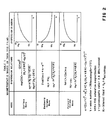
- the relationship between the frequency f mn of this resonance and the magnitude k mn of this resonance is nonlinear and depends on the direction of application of a bias field H O that is applied to the YIG film.
- the resulting magnetostatic waves are referred to as surface waves.
- the resulting magnetostatic waves are referred to as backward volume waves.
- the resulting magnetostatic waves are referred to as forward volume waves.
- the anisotropic field is the magnetic field introduced by the anisotropic structure of the crystal structure of the YIG film.
- the frequency is an increasing function of wavenumber, but for backward volume waves it is a decreasing function of frequency.
- m and n are both equal to 1.
- microstrip conductors 12 and 15 were aligned parallel to side 13 to a high degree of accuracy.
- other techniques can be utilized to suppress these unwanted (spurious) resonances for m ⁇ 1 (see, for example, copending U.S. patent application 094,963 entitled MODE SELECTIVE MAGNETOSTATIC WAVE RESONATORS.
- Such precise alignment and the inclusion of these other modes of suppression of these spurious modes increases the cost of these resonators. Therefore, it would be advantageous to have a new, simpler and less expensive means of suppressing the unwanted resonances and of channelling a greater fraction of the input signal into the resonant mode of interest.
- an MSW resonator in which the input transducer is oriented to produce travelling waves along the direction of the wave vector of a travelling wave component of the resonant fundamental mode of interest.
- the output transducer is also oriented to be maximally responsive to one of the travelling wave components of the resonant fundamental mode of interest.
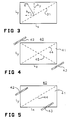
- FIG 3 a rectangular magnetostatic wave resonator cavity of width L x and width L y in which travelling waves are produced.
- a resonant response results when the wave vector of induced waves has x and y components satisfying the relationships.
- the frequency of this resonant mode is indicated by f mn and the associated wave vector is represented by k mn .
- the magnitude of k mn is represented by k mn .
- the resonant mode for f mn has the form (2) A.sin[(k mn ) x .x].sin[(k mn ) y .y] wher A is the amplitude of the resonant mode.
- This stationary state is really the superposition of the four travelling waves satisfying condition (1) above.
- the input transducer should be aligned to generate at least one of these four travelling waves.
- this wave reflects off of the end and side walls, the other three of these travelling waves will be produced and the resonant mode presented in equation (2) will result.
- a straight transducer will stimulate travelling waves perpendicular to the axis of the transducer, this axis should be oriented substantially perpendicular to the direction of the wave vector of the travelling wave component to be stimulated. Equivalently, the transducer should be parallel to the wavefront of the travelling wave component to be stimulated.
- dotted line 31 is the direction parallel to which the axis of the input transducer should be aligned in order to excite the travelling waves in the direction of the vector k in the figure and in the direction opposite to vector k .
- This orientation will be referred to herein as being such that "the transducer launches waves in the direction of the wave vector of one of the travelling wave components of the resonant mode signal".
- the resonator consists of a thin film 41 of a magnetic material (such as a thin film of yttrium iron garnet) grown by liquid phase epitaxy (LPE) on a gadolinium gallium garnet substrate, a first microstrip conductor 42 that serves as an input transducer, and a second microstrip conductor 43 that serves as an output transducer. Both transducers are selected to be parallel to a diagonal 44 of YIG film 41. However, in other embodiments, either of microstrip conductors 42 or 43 can be selected to be parallel to diagonal 45. In this embodiment, the transducers are positioned so that they are adjacent to, but do not overlap, the YIG film. In the embodiment In Figure 5, both transducers are positioned to overlap in YIG film.
- a magnetic material such as a thin film of yttrium iron garnet
- LPE liquid phase epitaxy
- An additional advantage of orienting the transducers parallel to a diagonal of film 41 is that the length of transducer overlapping the YIG film can be increased in comparison to the prior art transducer in Figure 1.
- a resonator shown in Figure 6, has its input microstrip 42 located on one diagonal and has its output microstrip conductor 43 located on the other diagonal of the YIG film.
- the overlapping portion of the transducer has a length L x
- the overlapping portion of the transducer has length [L x 2 + L y 2] 1/2 . This increased overlap increases the coupling strength of electrical signals in the microstrip to magnetostatic wave resonances in YIG film 41.
- the embodiment in Figure 6 has the further advantage that there is a reduced amount of coupling between conductors 42 and 43 via direct transmission of electromagnetic waves between them because there is a large relative angle ⁇ between these two conductors. For a square YIG film, this angle is 90° which minimizes the amount of direct coupling between conductors 42 and 43 via direct transmission of radio waves.
- the maximization of the coupling into the resonant mode of interest not only increases the resonant response of that mode, it also reduces the amount of energy remaining which can be coupled into the other resonant modes.
- the ratio of the spurious modes to the selected mode is decreased because there is a reduced amount of energy in the spurious modes and an increased amount of energy in the selected resonant mode.
- the lengths L x and L y can then be chosen to separate the resonances sufficiently that there is no significant overlap of neighbouring resonant peaks.
Landscapes
- Control Of Motors That Do Not Use Commutators (AREA)
- Surface Acoustic Wave Elements And Circuit Networks Thereof (AREA)
Applications Claiming Priority (2)
| Application Number | Priority Date | Filing Date | Title |
|---|---|---|---|
| US94961 | 1987-09-09 | ||
| US07/094,961 US4774483A (en) | 1987-09-09 | 1987-09-09 | Diagonally coupled magnetostatic wave resonators |
Publications (2)
| Publication Number | Publication Date |
|---|---|
| EP0307178A2 true EP0307178A2 (de) | 1989-03-15 |
| EP0307178A3 EP0307178A3 (de) | 1990-03-14 |
Family
ID=22248193
Family Applications (1)
| Application Number | Title | Priority Date | Filing Date |
|---|---|---|---|
| EP88308260A Withdrawn EP0307178A3 (de) | 1987-09-09 | 1988-09-07 | Diagonal gekoppelte magnetostatische Wellenresonatoren |
Country Status (3)
| Country | Link |
|---|---|
| US (1) | US4774483A (de) |
| EP (1) | EP0307178A3 (de) |
| JP (1) | JPS6471201A (de) |
Families Citing this family (3)
| Publication number | Priority date | Publication date | Assignee | Title |
|---|---|---|---|---|
| KR100361938B1 (ko) * | 2000-08-18 | 2002-11-22 | 학교법인 포항공과대학교 | 유전체 기판의 공진장치 |
| JP2012528545A (ja) * | 2009-05-28 | 2012-11-12 | ノースロップ グラマン システムズ コーポレーション | 横方向のオーバーモードバルク音響共振器 |
| US20150255846A1 (en) * | 2012-09-27 | 2015-09-10 | Northeastern University | Magnetostatic Surface Wave Nonreciprocal Tunable Bandpass Filters |
Family Cites Families (3)
| Publication number | Priority date | Publication date | Assignee | Title |
|---|---|---|---|---|
| FR2461368A1 (fr) * | 1979-07-06 | 1981-01-30 | Thomson Csf | Dispositif a ondes magnetostatiques comportant une structure d'echange a bandes conductrices |
| US4395686A (en) * | 1981-10-02 | 1983-07-26 | Westinghouse Electric Corp. | Attenuation of higher order width modes in magnetostatic wave devices |
| US4528529A (en) * | 1983-12-12 | 1985-07-09 | Hewlett-Packard Company | Magnetostatic wave resonator |
-
1987
- 1987-09-09 US US07/094,961 patent/US4774483A/en not_active Expired - Fee Related
-
1988
- 1988-08-29 JP JP63214725A patent/JPS6471201A/ja active Pending
- 1988-09-07 EP EP88308260A patent/EP0307178A3/de not_active Withdrawn
Also Published As
| Publication number | Publication date |
|---|---|
| EP0307178A3 (de) | 1990-03-14 |
| JPS6471201A (en) | 1989-03-16 |
| US4774483A (en) | 1988-09-27 |
Similar Documents
| Publication | Publication Date | Title |
|---|---|---|
| US4614923A (en) | Method of suppressing magnetostatic waves in magnetic garnet films for microwave circuit applications | |
| US4743874A (en) | Magnetostatic wave tunable resonator | |
| EP0307178A2 (de) | Diagonal gekoppelte magnetostatische Wellenresonatoren | |
| US4939488A (en) | Magnetostatic wave device | |
| EP0313342A2 (de) | Magnetostatische Wellenresonatoren vom selektiven Schwingungstyp | |
| US4392115A (en) | Volume magnetostatic wave device | |
| US4777462A (en) | Edge coupler magnetostatic wave structures | |
| US4716390A (en) | Magnetostatic wave channelizer | |
| US4472692A (en) | Tunable selective device using magnetostatic bulk waves | |
| Poston et al. | A new microwave ring resonator using guided magnetostatic surface waves | |
| US5168254A (en) | Magnetostatic wave device with minimized higher order mode excitations | |
| US3646486A (en) | Gyromagnetic isolator wherein even mode components are converted to odd mode components by biased ferrite | |
| JP2636580B2 (ja) | 静磁波装置 | |
| US5371482A (en) | Magnetostatic wave device containing acoustic wave absorbing layer | |
| JP3594499B2 (ja) | 静磁波素子 | |
| US5189383A (en) | Circuit element utilizing magnetostatic wave | |
| US5057800A (en) | Apparatus and method for diffracting MSW in a garnet film using SAW | |
| JPS62224101A (ja) | 静磁波フイルタバンク | |
| JPH0760965B2 (ja) | 静磁波装置 | |
| JP2608088B2 (ja) | フェリ磁性体薄膜共振器 | |
| JPH01233822A (ja) | 静磁波共振器 | |
| JPH039384Y2 (de) | ||
| JP2658306B2 (ja) | フェリ磁性体薄膜フィルタ | |
| JPH079443Y2 (ja) | Mswフィルタ | |
| JPH0728724Y2 (ja) | 静磁波装置 |
Legal Events
| Date | Code | Title | Description |
|---|---|---|---|
| PUAI | Public reference made under article 153(3) epc to a published international application that has entered the european phase |
Free format text: ORIGINAL CODE: 0009012 |
|
| AK | Designated contracting states |
Kind code of ref document: A2 Designated state(s): FR IT |
|
| PUAL | Search report despatched |
Free format text: ORIGINAL CODE: 0009013 |
|
| AK | Designated contracting states |
Kind code of ref document: A3 Designated state(s): FR IT |
|
| STAA | Information on the status of an ep patent application or granted ep patent |
Free format text: STATUS: THE APPLICATION HAS BEEN WITHDRAWN |
|
| 17P | Request for examination filed |
Effective date: 19900828 |
|
| 18W | Application withdrawn |
Withdrawal date: 19900918 |
|
| R18W | Application withdrawn (corrected) |
Effective date: 19900918 |