EP0308062A2 - Servodirection, numérique pour empilement de disques - Google Patents
Servodirection, numérique pour empilement de disques Download PDFInfo
- Publication number
- EP0308062A2 EP0308062A2 EP88307367A EP88307367A EP0308062A2 EP 0308062 A2 EP0308062 A2 EP 0308062A2 EP 88307367 A EP88307367 A EP 88307367A EP 88307367 A EP88307367 A EP 88307367A EP 0308062 A2 EP0308062 A2 EP 0308062A2
- Authority
- EP
- European Patent Office
- Prior art keywords
- pes
- sampling time
- disk
- head
- disk file
- Prior art date
- Legal status (The legal status is an assumption and is not a legal conclusion. Google has not performed a legal analysis and makes no representation as to the accuracy of the status listed.)
- Granted
Links
Images


Classifications
-
- G—PHYSICS
- G11—INFORMATION STORAGE
- G11B—INFORMATION STORAGE BASED ON RELATIVE MOVEMENT BETWEEN RECORD CARRIER AND TRANSDUCER
- G11B21/00—Head arrangements not specific to the method of recording or reproducing
- G11B21/02—Driving or moving of heads
- G11B21/08—Track changing or selecting during transducing operation
- G11B21/081—Access to indexed tracks or parts of continuous track
- G11B21/083—Access to indexed tracks or parts of continuous track on discs
- G11B21/085—Access to indexed tracks or parts of continuous track on discs with track following of accessed part
Definitions
- This invention relates to disk file digital servo control systems for read/write head positioning.
- Disk files are information storage devices which utilize a rotatable disk with concentric data tracks containing the information, a head for reading or writing data onto the various tracks, and an actuator connected by a support arm assembly to the head for moving the head to the desired track and maintaining it over the track centerline during read or write operations.
- the movement of the head to a desired track is referred to as track accessing or “seeking”, while the maintaining of the head over the centerline of the desired track during a read or write operation is referred to as track "following".
- the actuator is typically a "voice coil motor” (VCM) which comprises a coil movable through the magnetic field of a permanent magnetic stator.
- VCM voice coil motor
- the application of current to the VCM causes the coil, and thus the attached head, to move radially.
- the acceleration of the coil is proportional to the applied current, so that ideally there is no current to the coil if the head is perfectly stationary over a desired track.
- a servo control system In disk files which have a relatively high density of data tracks on the disk, it is necessary to incorporate a servo control system to maintain the head precisely over the centerline of the desired track during read or write operations. This is accomplished by utilizing prerecorded servo information either on a dedicated servo disk or on sectors angularly spaced and interspersed among the data on a data disk.
- the servo information sensed by the read/write head (or the dedicated servo head if a dedicated servo disk is used) is demodulated to generate a position error signal (PES) which is an indication of the position error of the head away from the nearest track centerline.
- PES position error signal
- a recent development in disk file servo control systems is a digital servo control system which, as part of the computation of the control signal to the actuator, makes use of a state estimator algorithm to estimate the position and velocity of the head.
- a microprocessor receives, at discrete sample times, digital values corresponding to the PES and the actuator input current, and computes, through the use of the state estimator algorithm, a digital control signal. The digital control signal is then converted to an analog signal and amplified to provide a new actuator input current.
- estimator constants are dependent upon the values of certain physical parameters of the disk file, such as the mass of the coil and head/arm assembly, the actuator force constant (the force applied to the coil per unit of input current), the gain of the VCM power amplifier, the PES gain and the time between PES samples (the PES sampling time).
- the estimator constants are generally referred to as "constants" because the values of the physical parameters from which they are determined are generally invariable.
- the PES sampling time which is the time between receipt of the PES samples by the microprocessor and thus the time between the beginning of consecutive control signal computations by the microprocessor, is a function of the speed of the drive motor which rotates the disks.
- disk file drive motors typically have a specified speed tolerance, e.g. plus/minus 3%.
- a variation in drive motor speed translates into a variation in the rate at which the head receives servo position information from the disk.
- the control signal generated by the microprocessor will be in error whenever the drive motor speed varies from its nominal speed. This control signal error will cause the head to undershoot or overshoot the target track when the head is moved between tracks, which could result in an unacceptable delay in the arrival of the head to the target track centerline, or in a seek error.
- the invention provides a digital servo control method for a disk file read/write head actuator, the method comprising processing from detected servo information a head position error signal (PES) and a clock signal representative of the beginning of a PES, and computing at discrete PES sampling times in response to digital values corresponding to the PES a digital control signal for use by the actuator, said computing including estimating the state of the actuator from, among other things, estimator constants, the estimator constants being determined by disk file physical parameters including the PES sampling time, the method being characterised by measuring the actual PES sampling time, and modifying said estimator constants in response to the measured actual PES sampling time.
- PES head position error signal
- clock signal representative of the beginning of a PES
- the invention provides a data recording disk file of the type having at least one rotatable disk with generally concentric data tracks thereon, the data disk or a separate servo disk having servo information recorded thereon, at least one head for reading the servo information during rotation of the disk, means for processing from the servo information a head position error signal (PES) and a clock signal representative of the beginning of a PES, an actuator responsive to an input signal and attached to the head for positioning the head, and computing means for receiving, at discrete PES sampling times, digital values corresponding to the PES and for computing a digital control signal for use by the actuator, said computing means including means for estimating the state of the actuator from, among other things, estimator constants, the estimator constants being determined by disk file physical parameters including the PES sampling time, the file being characterised by including means for measuring the actual PES sampling time, and by the computing means including means for modifying the estimator constants in response to the measured actual PES sampling time.
- PES head position error signal
- clock signal representative of
- a PES sampling clock generator receives the PES clock input corresponding to each discrete sample of servo timing information recorded on the disk, and generates a microprocessor interrupt signal.
- the frequency of the interrupt signal is thus directly related to the PES clock rate, which in turn is directly related to the drive motor speed.
- the sampling clock generator is designed such that its highest allowable frequency output, which corresponds to the highest allowable drive motor speed and thus the minimum allowable PES sampling time, is equal to the frequency at which the microprocessor generates the discrete control signals.
- the microprocessor recalls a previously stored value of PES sampling time (T) from a memory device and uses this value to modify the values of the estimator constants.
- the last instruction in the control signal algorithm is the reading into the memory device of a value equal to the minimum PES sampling time (T min ). If after this last instruction no interrupt is received from the sampling clock generator, the microprocessor continues to execute instructions to store in the memory device new values of PES sampling time, each successive value being incremented by an amount equal to the microprocessor cycle time. These instructions continue until an interrupt is received from the sampling clock generator. During the subsequent computation of the next control signal the new value of the PES sampling time is recalled from the memory device and used to modify the estimator constants. In this manner, for each new control signal computation, the actual PES sampling time is updated, stored in the memory device and recalled to modify the estimator constants during the next control signal computation. In the event the value of T exceeds the maximum allowable PES sampling time (T max ), corresponding to the slowest allowable drive motor speed, the microprocessor disables the VCM power amplifier and posts an error to the disk file control unit.
- T max the maximum allowable PES sampling time
- the digital servo control system uses the actual measured PES sampling time during each computation of the control signal, rather than relying upon a constant value based upon the nominal drive motor speed, the arrival of the head to the target track is substantially improved when there are variations in drive motor speed.
- less precise drive motors can be used in the disk file.
- a pair of disks 10, 12 are supported on a spindle 14 of a disk file drive motor 16.
- Each of the disks 10, 12 has two surfaces 20, 22 and 24, 26, respectively.
- surface 20 on disk 10 and surfaces 24, 26 on disk 12 are data recording surfaces.
- Surface 22 on disk 10 is a dedicated servo surface and contains only prerecorded servo information.
- the servo information on disk 10 is recorded in concentric tracks, with the position information typically written in such a manner that the intersections of adjacent servo tracks on servo surface 22 are radially aligned with the centerlines of the data tracks on surfaces 20, 24, and 26.
- a conventional quadrature servo pattern is depicted in Fig. 2.
- the servo pattern includes a synchronization area 27, which provides timing information corresponding to the beginning of a set of servo position blocks, and servo block area 29, which provides head position information.
- the specific tracks on the data disks and the servo disk are accessed by heads 30, 32, 34, 36, each of which is associated with a respective disk surface and supported by an associated arm assembly.
- the heads 30, 32, 34, 36 are attached to a common accessing means or actuator, such as VCM 40.
- VCM 40 a common accessing means or actuator
- the signal read by servo head 32 is input to amplifier 42 and then demodulator 44. While the invention may be applied to operate with any of numerous types of servo patterns and servo signal demodulation techniques, the servo control system will be explained with reference to the quadrature servo pattern, as represented in Fig. 2.
- the servo position information in block area 29 in the quadrature pattern on servo surface 22 is demodulated by demodulator 44 to generate two separate analog waveforms, designated primary (PESP) and quadrature (PESQ), as shown in Fig. 1.
- the analog PESP and PESQ signals from demodulator 44 are sent to analog-to-digital (A/D) converters 88, 89, respectively.
- the discrete values of PESP and PESQ at any sample time are designated PESP(n) and PESQ(n), where n represents a time index for each digital sample.
- a microprocessor 80 is connected by data bus 84 and suitable address bus (not shown) to suitable memory devices, such as read/write memory (RAM) 82 and programmable read only memory (PROM) 83.
- Micro processor 80 utilizes a control signal algorithm, as described in the aforementioned EP-A- 0243821 to generate a control signal u(n).
- the control signal u(n) is output to digital-to-analog converter (DAC) 92 and amplified by power amplifier 58 to generate an analog current i(t) to VCM 40.
- the analog current i(t) is fed back to analog-to-digital (A/D) converter 90, which provides a digital current signal i(n) to microprocessor 80.
- A/D analog-to-digital
- Microprocessor 80 thus receives as inputs, at discrete sample times, the digital actuator current i(n) and the digital head position error signals PESP(n) and PESQ(n). Microprocessor 80 computes the actual position error signal PES(n) from the values of PESP(n) and PESQ(n), using conventional logic, as described in EP-A- 0243821.
- demodulator 44 demodulates the position information in servo block area 29 from the quadrature servo pattern (Fig. 2) to generate analog PESP and PESQ signals.
- Demodulator 44 also contains synchronization detection circuitry 45 which receives the timing information from the synchronization areas 27 of the quadrature servo pattern and outputs a PES clock signal.
- the PES clock signal is output by synchronization detection circuitry 45 at a frequency corresponding to the rate at which the synchronization areas 27 in the servo pattern pass beneath the servo head 32.
- the PES clock frequency is determined by the number of discrete sets of servo position blocks 29, (and thus the number of corresponding synchronization areas 27) recorded either on the dedicated servo disk or in sectors on the data disk, and the rotational speed of the drive motor 16. Since the number and spacing of recorded synchronization areas 27 are fixed, the PES clock frequency is solely a function of the rotational speed of drive motor 16.
- the PES clock signal synchronization detection circuitry 45 is input to a sampling clock generator 65 which provides an interrupt signal to microprocessor 80.
- Sampling clock generator 65 may be a digital counter which divides the PES clock frequency by a fixed value to provide an interrupt signal at a frequency substantially slower than the PES clock input frequency.
- the combination of the synchronization areas 27 recorded on the disk and the nominal speed of drive motor 16 results in a PES clock frequency of approximately 3 MHz, corresponding to a time between PES clock pulses of approximately 330 nanoseconds (ns).
- the sampling clock generator 65 is a divide-by-336 digital counter which is reset for every revolution of the drive motor 16 by an index pulse corresponding to the beginning of a servo track and recorded on servo disk surface 22.
- the frequency of the interrupt signal generated by the sampling clock generator 65 in response to this nominal PES clock input frequency is approximately 8.9 kHz (3MHz/336). This corresponds to a time between interrupt signals of approximately 112 microseconds.
- the time between PES clock pulses can vary between plus/minus approximately 10 ns, and the time between interrupt signals from sampling clock generator 65 can vary between plus/minus approximately 3.4 microseconds.
- Each interrupt signal to microprocessor 80 initiates the beginning of the control signal algorithm.
- the time between interrupts received by microprocessor 80 corresponds to the PES sampling time, the value of which affects the values of the estimator constants used in the state estimator portion of the control signal algorithm.
- K x PES gain
- K f VCM force constant (the force generated by the VCM per unit of input current)
- K p power amplifier gain
- T PES sampling time
- D computation time delay between availability of analog PES and availability of digital control signal
- m T - D
- M mass of coil and head arm assembly.
- the p ij , g ij terms are generally invariable since they are functions of physical parameters of the disk file which do not generally change.
- the disk drive motor 16 has a tolerance about its nominal rotational speed which causes the PES sampling time T to vary accordingly. If the nominal sampling time T is maintained as a constant during the computation of the control signal, then the head velocity predicted by the state estimator will be higher or lower then the actual head velocity whenever the disk drive motor speed varies from its nominal value. The result will be an unacceptable undershoot or overshoot of the head to the target track during a track seek, which significantly increases the access time of the actuator.
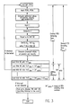
- Fig. 3 there is illustrated a flow chart for the control signal algorithm which incorporates the measured actual PES sampling time (T).
- the microprocessor 80 begins the control signal computation upon receipt of an interrupt.
- the PESP and PESQ values are then read and the estimated values of head position, velocity and acceleration are computed from the previous predicted values.
- the specific equations for the computation of the estimated and predicted values are set out in EP-A- 0243821.
- the value of actuator input current "i" is then read, and the digital control signal "u” is computed and output to DAC 92.
- the next instruction is to modify the values of p ij and g ij by recomputing them, based upon the actual value of T in RAM 82.
- the initial value of T which is the value used for the first control signal calculation after power on, may be either part of the algorithm or recalled from PROM 83).
- the predicted values of head position and velocity are computed through the use of the state estimator and the modified estimator constants.
- the next instruction in the algorithm is to write to RAM 82 a predetermined value of T equal to the minimum PES sampling time (T min ).
- T min which corresponds to the highest possible drive motor speed, is selected to be equal to the time required for microprocessor 80 to run the complete control signal algorithm from receipt of the interrupt to execution of the instruction to store T min in RAM 82. As indicated in Fig.
- the microprocessor 80 continues to perform additional instructions, each of which is to write into RAM 82 a new value of T incremented by T delta , where T delta equals the cycle time of microprocessor 80.
- T delta equals the cycle time of microprocessor 80.
- RAM 82 is continually updated with the actual PES sampling time and this actual value is recalled and used to modify the estimator constants p ij and g ij .
- the maximum number of microprocessor cycles N which can be run after the writing of T min to RAM 82 is selected so that N * T delta equals the range of PES sampling time variation. If no interrupt is received after N microprocessor cycles, the microprocessor 80 posts an error to the disk file control unit and disables VCM power amplifier 58.
- the nominal PES sampling time is 112 microseconds, which is the nominal time between interrupts output by sampling clock generator 65 and corresponds to the drive motor running at its nominal speed; T min equals approximately 109 microseconds and T max equals approximately 115 microseconds.
- the microprocessor has a cycle time of 200 ns.
- the value of N is selected to be 30 so that 30 additional instructions (corresponding to 6 microseconds) for the computation of T can occur after the loading of RAM 82 with T min . The execution of all 30 additional instructions would occur only if the drive motor speed was at its slowest allowable speed.
- Fig. 3 illustrates an embodiment which requires that N additional instructions be stored in PROM 83, but which maximizes the PES sampling time accuracy because the PES sampling time increment is just one microprocessor cycle, i.e. the time to load a new value of T into RAM 82.
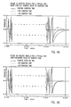
- Figs. 4A and 4B The improved performance of a digital servo control system embodying the present invention is depicted in Figs. 4A and 4B.
- Fig. 4A there is illustrated the variation of the PES voltage during a typical track seek for three different speeds of the drive motor: a nominal speed indicated by the solid line, a speed of 3% greater than nominal indicated by the dotted line, and a speed 3% less than nominal indicated by the dashed line.
- Fig. 4A that whenever the drive motor is operating other than at nominal speed, there is degraded performance in the arrival of the head to the target track because of the incorrect values of the estimator constants used to generate the estimated head position and velocity as part of the control signal computation.
- the same three track seeks are depicted in Fig.
- the above described technique for utilizing the actual PES sampling time to modify the estimator constants p ij and g ij is the preferred embodiment.
- One such embodiment is depicted in Fig. 5.
- the output of sampling clock generator 65 which will have a nominal frequency with a tolerance corresponding to the tolerance of the drive motor speed tolerance, is output to a frequency-to-voltage converter 67.
- the output from frequency-to-voltage converter 67 is a DC voltage which is directly related to the frequency output from sampling clock generator 65.
- This DC voltage is then converted to a digital value by A/D converter 68 and input to data bus 84 where it is available for reading by microprocessor 80.
- the microprocessor 80 directly reads a value corresponding to the actual PES sampling time and uses that value to modify the estimator constants during the computation of the control signal.
Landscapes
- Moving Of The Head To Find And Align With The Track (AREA)
- Moving Of Head For Track Selection And Changing (AREA)
- Feedback Control In General (AREA)
Applications Claiming Priority (2)
| Application Number | Priority Date | Filing Date | Title |
|---|---|---|---|
| US97787 | 1979-11-27 | ||
| US07/097,787 US4816941A (en) | 1987-09-16 | 1987-09-16 | Disk file digital servo control system with optimized sampling rate |
Publications (3)
| Publication Number | Publication Date |
|---|---|
| EP0308062A2 true EP0308062A2 (fr) | 1989-03-22 |
| EP0308062A3 EP0308062A3 (en) | 1990-01-31 |
| EP0308062B1 EP0308062B1 (fr) | 1992-10-21 |
Family
ID=22265131
Family Applications (1)
| Application Number | Title | Priority Date | Filing Date |
|---|---|---|---|
| EP88307367A Expired EP0308062B1 (fr) | 1987-09-16 | 1988-08-09 | Servodirection, numérique pour empilement de disques |
Country Status (5)
| Country | Link |
|---|---|
| US (1) | US4816941A (fr) |
| EP (1) | EP0308062B1 (fr) |
| JP (1) | JPH0828072B2 (fr) |
| CA (1) | CA1317372C (fr) |
| DE (1) | DE3875439T2 (fr) |
Cited By (6)
| Publication number | Priority date | Publication date | Assignee | Title |
|---|---|---|---|---|
| WO1991010991A1 (fr) * | 1990-01-11 | 1991-07-25 | Siemens Nixdorf Informationssysteme Aktiengesellschaft | Procede et circuit servant au reglage du bras d'acces d'un systeme de memoire a disques |
| EP0516854A4 (en) * | 1990-12-21 | 1993-03-17 | Fujitsu Limited | Device for controlling positioning of head of disc drive and method of controlling the same |
| WO1999045535A1 (fr) * | 1998-03-05 | 1999-09-10 | Convolve, Inc. | Procede de commande de systeme dynamique |
| US6560658B2 (en) | 1999-03-04 | 2003-05-06 | Convolve, Inc. | Data storage device with quick and quiet modes |
| US6704159B2 (en) | 2000-06-20 | 2004-03-09 | Seagate Technology Llc | Automatic acoustic management system for a disc drive |
| US7982999B2 (en) | 1994-06-07 | 2011-07-19 | Hitachi Global Storage Technologies Japan, Ltd. | Information storing device and method for controlling same to record/reproduce information by selecting one of working modes |
Families Citing this family (27)
| Publication number | Priority date | Publication date | Assignee | Title |
|---|---|---|---|---|
| US4894599A (en) * | 1988-03-31 | 1990-01-16 | International Business Machines Corporation | deadbeat control of disk drive actuator |
| US5369345A (en) * | 1992-03-31 | 1994-11-29 | Seagate Technology, Inc. | Method and apparatus for adaptive control |
| US5477103A (en) * | 1993-06-04 | 1995-12-19 | Cirrus Logic, Inc. | Sequence, timing and synchronization technique for servo system controller of a computer disk mass storage device |
| US5576910A (en) * | 1993-06-04 | 1996-11-19 | Cirrus Logic, Inc. | Burst comparison and sequential technique for determining servo control in a mass storage disk device |
| US5691617A (en) * | 1993-07-12 | 1997-11-25 | Seagate Technology, Inc. | Disc drive transducer deadbeat settle method utilizing interval correction |
| US5384524A (en) * | 1993-09-02 | 1995-01-24 | Cirrus Logic, Inc. | Voice coil motor control circuit and method for servo system control in a computer mass storage device |
| JP3829994B2 (ja) * | 1995-01-06 | 2006-10-04 | 富士通株式会社 | ファイル装置の開発装置及び開発システム |
| KR100245145B1 (ko) * | 1995-10-24 | 2000-02-15 | 포만 제프리 엘 | 자기헤드의 위치 검출방법 및 자기 디스크 장치 |
| US20030054203A1 (en) * | 1997-10-22 | 2003-03-20 | Quantum Corporation, A California Corporation | Magnetic tape |
| US6084740A (en) | 1997-12-01 | 2000-07-04 | Storage Technology Corporation | Optical servo system for a tape drive |
| US6166876A (en) * | 1998-02-24 | 2000-12-26 | Seagate Technology, Inc. | Minimizing settling time in a disc drive servo system |
| GB2335785B (en) | 1998-03-24 | 2002-09-18 | Quantum Corp | Multi-channel magnetic tape system having optical tracking servo |
| US7029726B1 (en) | 1999-07-27 | 2006-04-18 | Quantum Corporation | Method for forming a servo pattern on a magnetic tape |
| US7153366B1 (en) | 1998-03-24 | 2006-12-26 | Quantum Corporation | Systems and method for forming a servo pattern on a magnetic tape |
| US6219198B1 (en) | 1998-07-14 | 2001-04-17 | International Business Machines Corporation | State estimator alteration for odd sample times in a disk drive servo control system |
| US6741415B1 (en) | 1999-02-16 | 2004-05-25 | Quantum Corporation | Method of writing servo signal on magnetic tape |
| EP1205913A4 (fr) | 1999-02-17 | 2002-08-14 | Quantum Corp | Procede d'ecriture de signaux d'asservissement sur une bande magnetique |
| US6442705B1 (en) * | 1999-04-26 | 2002-08-27 | International Business Machines Corporation | Method of and apparatus for improving data integrity in a disk drive system |
| US6961200B2 (en) * | 1999-07-27 | 2005-11-01 | Quantum Corporation | Optical servo track identification on tape storage media |
| US20030189782A1 (en) * | 2002-04-04 | 2003-10-09 | Storage Technology Corporation | Optical servo system for a tape drive |
| US6558774B1 (en) | 1999-08-17 | 2003-05-06 | Quantum Corporation | Multiple-layer backcoating for magnetic tape |
| US6940676B1 (en) | 2000-06-07 | 2005-09-06 | Quantum Corporation | Triple push-pull optical tracking system |
| US6940681B2 (en) | 2001-08-20 | 2005-09-06 | Quantum Corporation | Optical to magnetic alignment in magnetic tape system |
| US7023650B2 (en) | 2001-11-07 | 2006-04-04 | Quantum Corporation | Optical sensor to recording head alignment |
| US7187515B2 (en) * | 2003-02-05 | 2007-03-06 | Quantum Corporation | Method and system for tracking magnetic media with embedded optical servo tracks |
| US6980390B2 (en) * | 2003-02-05 | 2005-12-27 | Quantum Corporation | Magnetic media with embedded optical servo tracks |
| US7119511B2 (en) | 2003-04-11 | 2006-10-10 | International Business Machines Corporation | Servo system for a two-dimensional micro-electromechanical system (MEMS)-based scanner and method therefor |
Family Cites Families (6)
| Publication number | Priority date | Publication date | Assignee | Title |
|---|---|---|---|---|
| US4204234A (en) * | 1978-10-27 | 1980-05-20 | International Business Machines Corporation | System for positioning single gap magnetic head to follow moving recorded data track |
| GB2039078B (en) * | 1978-12-27 | 1982-11-24 | Ibm | Sampled data servo positioning system |
| US4646175A (en) * | 1984-04-05 | 1987-02-24 | Irwin Magnetic Systems, Inc. | Method and apparatus for positioning transducers by digital conversion of analog-type signals |
| DE3776928D1 (de) * | 1986-03-19 | 1992-04-09 | Fujitsu Ltd | Regelsystem zum spurzugriff fuer ein magnetplattensystem. |
| US4679103A (en) * | 1986-04-29 | 1987-07-07 | International Business Machines Corporation | Digital servo control system for a data recording disk file |
| US4697127A (en) * | 1986-06-09 | 1987-09-29 | International Business Machines Corporation | Adaptive control technique for a dynamic system |
-
1987
- 1987-09-16 US US07/097,787 patent/US4816941A/en not_active Expired - Lifetime
-
1988
- 1988-07-20 JP JP63179349A patent/JPH0828072B2/ja not_active Expired - Lifetime
- 1988-08-09 EP EP88307367A patent/EP0308062B1/fr not_active Expired
- 1988-08-09 DE DE8888307367T patent/DE3875439T2/de not_active Expired - Fee Related
- 1988-09-16 CA CA000577642A patent/CA1317372C/fr not_active Expired - Fee Related
Cited By (12)
| Publication number | Priority date | Publication date | Assignee | Title |
|---|---|---|---|---|
| WO1991010991A1 (fr) * | 1990-01-11 | 1991-07-25 | Siemens Nixdorf Informationssysteme Aktiengesellschaft | Procede et circuit servant au reglage du bras d'acces d'un systeme de memoire a disques |
| EP0516854A4 (en) * | 1990-12-21 | 1993-03-17 | Fujitsu Limited | Device for controlling positioning of head of disc drive and method of controlling the same |
| US5844744A (en) * | 1990-12-21 | 1998-12-01 | Fujitsu Limited | Head positioning control apparatus of disk drive and method of controlling the same apparatus |
| US7982999B2 (en) | 1994-06-07 | 2011-07-19 | Hitachi Global Storage Technologies Japan, Ltd. | Information storing device and method for controlling same to record/reproduce information by selecting one of working modes |
| US8345371B2 (en) | 1994-06-07 | 2013-01-01 | Hitachi Global Storage Technologies Japan, Ltd. | Information storing device and method for controlling same to record/reproduce information by selecting one of working modes |
| WO1999045535A1 (fr) * | 1998-03-05 | 1999-09-10 | Convolve, Inc. | Procede de commande de systeme dynamique |
| US6314473B1 (en) | 1998-03-05 | 2001-11-06 | Convolve, Inc. | System for removing selected unwanted frequenices in accordance with altered settings in a user interface of a data storage device |
| US6560658B2 (en) | 1999-03-04 | 2003-05-06 | Convolve, Inc. | Data storage device with quick and quiet modes |
| US7433144B2 (en) | 1999-03-04 | 2008-10-07 | Convolve, Inc. | Dynamic system control method |
| US7483232B2 (en) | 1999-03-04 | 2009-01-27 | Convolve, Inc. | Dynamic system control method |
| US7620739B2 (en) | 1999-03-04 | 2009-11-17 | Convolve, Inc. | Dynamic system control method |
| US6704159B2 (en) | 2000-06-20 | 2004-03-09 | Seagate Technology Llc | Automatic acoustic management system for a disc drive |
Also Published As
| Publication number | Publication date |
|---|---|
| DE3875439T2 (de) | 1993-04-22 |
| DE3875439D1 (de) | 1992-11-26 |
| JPH01169785A (ja) | 1989-07-05 |
| JPH0828072B2 (ja) | 1996-03-21 |
| US4816941A (en) | 1989-03-28 |
| CA1317372C (fr) | 1993-05-04 |
| EP0308062B1 (fr) | 1992-10-21 |
| EP0308062A3 (en) | 1990-01-31 |
Similar Documents
| Publication | Publication Date | Title |
|---|---|---|
| EP0308062B1 (fr) | Servodirection, numérique pour empilement de disques | |
| EP0308070B1 (fr) | Fichier à guide d'enregistrement de données avec commande d'asservissement numérique | |
| US5072318A (en) | Disk file with adaptive cancellation of nonrepeatable disk runout | |
| EP0243821B1 (fr) | Système d'asservissement pour disque d'enregistrement de données | |
| US5576909A (en) | Method for positioning a data transducer head in a rotating disk drive data storage device | |
| US4835633A (en) | Disk file digital servo control system with compensation for variation in actuator acceleration factor | |
| EP0361786B1 (fr) | Commande d'asservissement numérique pour mémoire à disques | |
| CA1279930C (fr) | Methode et dispositif de recherche selective asservie et d'entrainement de disque autopointe perfectionne | |
| US5182684A (en) | Estimator positioning system and method | |
| US5917672A (en) | Disk file head positioning servo system incorporating adaptive saturated seek and head offset compensation | |
| US5381282A (en) | Inter-sample switching of servo control in direct access storage devices | |
| EP0108060B1 (fr) | Commande de recherche a asservissement par secteur | |
| US5473550A (en) | Fast calibration using microsteps | |
| US6313964B1 (en) | Early write enable with off-track write protection | |
| CA1189187A (fr) | Asservissement de la recherche dans une unite de disques magnetiques | |
| US5659438A (en) | Head positioning control system using stored voice coil motor correction data | |
| US5847527A (en) | Method and apparatus for digital position control | |
| JP2731483B2 (ja) | オフトラック補正機能を有する磁気ディスク装置 | |
| JP2650720B2 (ja) | ヘッド位置決め制御方法およびそれを用いたディスク装置 | |
| KR100493146B1 (ko) | 멀티레이트추정장치및그방법 | |
| JP2595941B2 (ja) | ヘッドのシーク位置決め方法 | |
| JPH0330157A (ja) | 磁気デイスク装置の位置制御装置 | |
| JPH0330155A (ja) | 磁気デイスク装置の位置制御装置 |
Legal Events
| Date | Code | Title | Description |
|---|---|---|---|
| PUAI | Public reference made under article 153(3) epc to a published international application that has entered the european phase |
Free format text: ORIGINAL CODE: 0009012 |
|
| AK | Designated contracting states |
Kind code of ref document: A2 Designated state(s): DE FR GB IT |
|
| 17P | Request for examination filed |
Effective date: 19890720 |
|
| PUAL | Search report despatched |
Free format text: ORIGINAL CODE: 0009013 |
|
| AK | Designated contracting states |
Kind code of ref document: A3 Designated state(s): DE FR GB IT |
|
| 17Q | First examination report despatched |
Effective date: 19911022 |
|
| GRAA | (expected) grant |
Free format text: ORIGINAL CODE: 0009210 |
|
| AK | Designated contracting states |
Kind code of ref document: B1 Designated state(s): DE FR GB IT |
|
| PG25 | Lapsed in a contracting state [announced via postgrant information from national office to epo] |
Ref country code: IT Free format text: LAPSE BECAUSE OF FAILURE TO SUBMIT A TRANSLATION OF THE DESCRIPTION OR TO PAY THE FEE WITHIN THE PRESCRIBED TIME-LIMIT;WARNING: LAPSES OF ITALIAN PATENTS WITH EFFECTIVE DATE BEFORE 2007 MAY HAVE OCCURRED AT ANY TIME BEFORE 2007. THE CORRECT EFFECTIVE DATE MAY BE DIFFERENT FROM THE ONE RECORDED. Effective date: 19921021 |
|
| REF | Corresponds to: |
Ref document number: 3875439 Country of ref document: DE Date of ref document: 19921126 |
|
| ET | Fr: translation filed | ||
| PLBE | No opposition filed within time limit |
Free format text: ORIGINAL CODE: 0009261 |
|
| STAA | Information on the status of an ep patent application or granted ep patent |
Free format text: STATUS: NO OPPOSITION FILED WITHIN TIME LIMIT |
|
| 26N | No opposition filed | ||
| PGFP | Annual fee paid to national office [announced via postgrant information from national office to epo] |
Ref country code: GB Payment date: 19950726 Year of fee payment: 8 |
|
| PGFP | Annual fee paid to national office [announced via postgrant information from national office to epo] |
Ref country code: FR Payment date: 19950807 Year of fee payment: 8 |
|
| PGFP | Annual fee paid to national office [announced via postgrant information from national office to epo] |
Ref country code: DE Payment date: 19950821 Year of fee payment: 8 |
|
| PG25 | Lapsed in a contracting state [announced via postgrant information from national office to epo] |
Ref country code: GB Effective date: 19960809 |
|
| GBPC | Gb: european patent ceased through non-payment of renewal fee |
Effective date: 19960809 |
|
| PG25 | Lapsed in a contracting state [announced via postgrant information from national office to epo] |
Ref country code: FR Effective date: 19970430 |
|
| PG25 | Lapsed in a contracting state [announced via postgrant information from national office to epo] |
Ref country code: DE Effective date: 19970501 |
|
| REG | Reference to a national code |
Ref country code: FR Ref legal event code: ST |