EP0308347B1 - Prüfkopfmanipulator mit verbesserter Aufhängung - Google Patents
Prüfkopfmanipulator mit verbesserter Aufhängung Download PDFInfo
- Publication number
- EP0308347B1 EP0308347B1 EP88402347A EP88402347A EP0308347B1 EP 0308347 B1 EP0308347 B1 EP 0308347B1 EP 88402347 A EP88402347 A EP 88402347A EP 88402347 A EP88402347 A EP 88402347A EP 0308347 B1 EP0308347 B1 EP 0308347B1
- Authority
- EP
- European Patent Office
- Prior art keywords
- block
- axis
- frame
- test head
- suspension member
- Prior art date
- Legal status (The legal status is an assumption and is not a legal conclusion. Google has not performed a legal analysis and makes no representation as to the accuracy of the status listed.)
- Expired - Lifetime
Links
Images

Classifications
-
- G—PHYSICS
- G01—MEASURING; TESTING
- G01R—MEASURING ELECTRIC VARIABLES; MEASURING MAGNETIC VARIABLES
- G01R31/00—Arrangements for testing electric properties; Arrangements for locating electric faults; Arrangements for electrical testing characterised by what is being tested not provided for elsewhere
- G01R31/28—Testing of electronic circuits, e.g. by signal tracer
- G01R31/2851—Testing of integrated circuits [IC]
- G01R31/2886—Features relating to contacting the IC under test, e.g. probe heads; chucks
- G01R31/2887—Features relating to contacting the IC under test, e.g. probe heads; chucks involving moving the probe head or the IC under test; docking stations
-
- B—PERFORMING OPERATIONS; TRANSPORTING
- B23—MACHINE TOOLS; METAL-WORKING NOT OTHERWISE PROVIDED FOR
- B23Q—DETAILS, COMPONENTS, OR ACCESSORIES FOR MACHINE TOOLS, e.g. ARRANGEMENTS FOR COPYING OR CONTROLLING; MACHINE TOOLS IN GENERAL CHARACTERISED BY THE CONSTRUCTION OF PARTICULAR DETAILS OR COMPONENTS; COMBINATIONS OR ASSOCIATIONS OF METAL-WORKING MACHINES, NOT DIRECTED TO A PARTICULAR RESULT
- B23Q1/00—Members which are comprised in the general build-up of a form of machine, particularly relatively large fixed members
- B23Q1/25—Movable or adjustable work or tool supports
- B23Q1/44—Movable or adjustable work or tool supports using particular mechanisms
- B23Q1/48—Movable or adjustable work or tool supports using particular mechanisms with sliding pairs and rotating pairs
-
- G—PHYSICS
- G01—MEASURING; TESTING
- G01R—MEASURING ELECTRIC VARIABLES; MEASURING MAGNETIC VARIABLES
- G01R1/00—Details of instruments or arrangements of the types included in groups G01R5/00 - G01R13/00 and G01R31/00
- G01R1/02—General constructional details
- G01R1/06—Measuring leads; Measuring probes
- G01R1/067—Measuring probes
- G01R1/06705—Apparatus for holding or moving single probes
-
- G—PHYSICS
- G12—INSTRUMENT DETAILS
- G12B—CONSTRUCTIONAL DETAILS OF INSTRUMENTS, OR COMPARABLE DETAILS OF OTHER APPARATUS, NOT OTHERWISE PROVIDED FOR
- G12B9/00—Housing or supporting of instruments or other apparatus
- G12B9/08—Supports; Devices for carrying
Definitions
- the invention relates to the technical field of manipulator devices designed for the support and orientation of an electronic test head ensuring the connection interface between an automatic test equipment and electronic circuits, simple or complex, to be tested, loaded onto a presentation structure.
- the devices of the above type are intended to allow the adjustment of position in elevation, in azimuth and in orientation of a support on which the head is mounted, so as to allow, by manual displacement, docking and connection of this head with the presentation structure of the electronic circuits to be tested.
- Electronic test heads are high-weight assemblies formed by a support and protection structure containing a large number of control circuits extended externally to the head by connection cables. Each integrated circuit to be tested is successively placed on the test head from a presentation structure to which the head is mechanically connected.
- Such heads are organized in the form of boxes of approximately parallelepipedal shape capable of being supported by two pins fixed on either side of the box. As the weight of the head is uniformly distributed with respect to these pins, the head is suspended in indifferent equilibrium by the two pins.
- asymmetrical include a cylindrical envelope extended radially by a rigid arm which contains electrical connection cables and cooling pipes.
- test head manipulators such as that described in European patent application EP-A-102 217, comprise a column constituted by an "H" shaped beam on which an articulated arm is slidably mounted vertically.
- the articulated arm has two vertical axes necessary to support the weight of the test head when the latter is moved manually away from or closer to the column. In this device, the articulated arm cannot be moved in 360 ° rotation around the column.
- the H-beam has a long length because its top must be higher than the highest position of the test head so that the column is heavy and bulky.
- Such a manipulator further comprises metallic masses which are removed or added to balance the weight of the test head. These metallic masses are not practical to handle and do not allow continuous adjustment.
- the articulated arm does not allow significant horizontal movements.
- manipulators include compressed air balancing means for vertically moving and supporting the weight of the test head.
- These balancing means are complicated because they require a compressor, a pressure regulator and preferably a damping system which operate continuously to maintain a constant pressure during vertical movements of the head.
- An object of the invention is to provide a manipulator device having a small vertical footprint and offering possibilities of displacement in site over 360 ° all around the vertical suspension column.
- Another object of the invention is to provide a manipulator device having a relatively simple balancing system, capable of being adjusted continuously and which does not require the manipulation of removable masses to balance the weight of the test head.
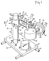
- Figure 1 is a schematic perspective view illustrating a device for manipulating the support and orientation of an electronic test head according to the invention.
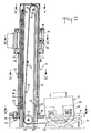
- FIG. 2 is an elevation in partial section of the column and of the balancing means of the apparatus of FIG. 1.
- Figures 3, 4, 5 and 6 are plan views, in partial section, taken respectively along lines III-III, IV-IV, V-V and VI-VI of Figure 2.
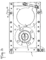
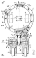
- FIG. 7 is a sectional elevation partially cut away from the orientation device of the device of FIG. 1.
- FIG. 8 is a plan view, partially broken away, taken along the line VIII-VIII of FIG. 7.
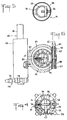
- FIG. 9 is a cross section along the line IX-IX in FIG. 7.
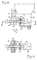
- Figure 10 is a partial sectional elevation showing, on a larger scale, an alternative embodiment of the adjusting means of the manipulator.
- Figure 11 is a section taken along line XI-XI of Figure 10.
- FIG. 1 schematically shows a manipulator device 10 for supporting and orienting an electronic test head 11, of the asymmetrical type, provided with a radial fixing arm 12.
- An apparatus such as 10, generally comprises a base 13 from which rises a suspension column 14 provided with positioning means 15 capable of ensuring the displacement of an orientation device 16 in general directions x , y and z .
- the positioning means 15 make it possible to move the test head 11 in three movements: a rotation (y) around the column 14, a translational movement along a horizontal direction (x) and a rotation around a vertical axis ( ⁇ z). Added to the vertical movement authorized by the suspension column 14, these three movements allow the test head 11 to be brought to any position all around the column 14.
- the orientation device 16 allows two additional movements of the head test 11: a rotation around a horizontal axis ⁇ x and a rotation around an axis ⁇ y.
- the column 14 comprises a fixed suspension member or tubular barrel 20 fixed to the base 13.
- the base 13 comprises a base 21, of any suitable geometric shape, associated with feet 22 mounted orientable on vertical articulation axes 23.
- the feet 22 are only partially shown in Figures 1 and 3. They can be made in any suitable manner by being of fixed or adjustable length.
- the fixed tubular barrel 20 is fixed, by any suitable means, to the base 21.
- the barrel 20 comprises at the bottom a flange 24 by which it is fixed to the base 21, in particular through bolts 25.
- the column 14 furthermore comprises a mobile suspension member or tubular sheath 26 threaded concentrically on the barrel 20 with which it cooperates by guide members 27 and by centering members 28, illustrated in more detail in FIG. 4.
- the guide members 27 prevent the sleeve 26 from rotating around the barrel 20. They include an axial rule 30 which is fixed to the periphery of the fixed tubular barrel 20.
- the members 27 furthermore comprise at least two sets of two rollers 31 carried by the sleeve 26, so as to cooperate for each pair with the two lateral faces of the axial rule 30.
- the two pairs of rollers 31 are arranged at a distance from one another, from the lower end of the tubular sleeve 26 so as to be able to cooperate with the major part of the length of the rule 30 and thus allow the telescopic axial displacement of the sleeve 26 over the main useful part of the height of the barrel tubular 20.
- the position of maximum extension of the sleeve 26 relative to the barrel 20 is determined by a stopper stopper 32 (FIG. 5) adapted to the upper end of the rule 30 to oppose the movement of the rollers 31 of the upper pair 27.
- the position of maximum retraction, as illustrated in FIG. 2, is determined by bringing the lower end of the sleeve 26 into abutment against the base 21, either directly or with the interposition of a lining 33, for example made of elastomer, assuming a function of support and damping crown.
- the centering members 28 are mainly constituted by rollers 34 mounted on yokes 35 carried by the sheath 26 so as to be able to roll axially on the outer periphery of the barrel 20.
- the rollers 34 are organized in two series spaced axially one measure , for example, equal to that separating the two pairs of rollers 31.
- the rollers 34 are angularly equidistant in each series.
- Figure 4 shows that, preferably, each series comprises four rollers 34 two with two diametrically opposite.
- the yokes 35 can be produced in various possible ways.
- a suitable structure consists in making them comprise a collar by which they are fixed in a removable manner on the external surface of the sheath 26 which the yokes cross freely.
- the sleeve 26 is thus guided axially and angularly, while being centered on the barrel 20 with respect to which it can be moved with minimal friction, due to the presence of the rollers 31 and 34.
- the sleeve 26 can thus be placed in the retraction position corresponding to the minimum height of the column 14 as illustrated in FIG. 2.
- the sleeve 26 can also be raised easily to its position of maximum extension by telescopic sliding to the position of stop determined by the support of the first pair of rollers 31 against the cleat 32.
- at least some of the rollers 31 and 34 are mounted by eccentric rings on their axes.
- the manipulator includes means for balancing the weight of the test head.
- the sleeve 26 is connected, by a flexible transmission 40, to adjustable traction means 41 carried by the base 21.
- the flexible transmission 40 comprises a cable whose end eyelet 42 is hooked, by a fixing means 43 , inside the sheath 26 and near the lower end of the latter.
- the cable 40 rises in the annular gap between the sheath 26 and the barrel 20, to be supported by a return pulley 44 carried by an axis of rotation 45 fixed at the head of the barrel 20.
- the cable 40 extends axially inside the drum 20 and passes over a foot deflection pulley 46 carried by a rotation axis 47 fixed to the base of the drum 20.
- the cable 40 is oriented substantially horizontally, through a lumen 48 of the barrel 20 to be supported by the traction means 41.
- the traction means 41 apply an adjustable elastic traction to the cable 40.
- the traction means 41 comprise an envelope 50 fixed to the base 21 and containing a drum 51 having a helical groove with a turn diameter progressively increasing on which the cable 40 is wound. When the sheath 26 is in the high position, all the turns of the cable 40 are wound on the drum 51.
- the traction means 41 also comprise a leaf spring 52 of the hairspring type whose internal attachment hand is anchored on the drum 51.
- the adjustment of the traction means 41 is carried out, according to the weight of the test head, so as to bring the test head vertically to a neutral position chosen for which the elastic traction action compensates for the weight of the moving assembly including the head, this weight applying to the cable 40 in the direction of the arrows f1 and f2.
- the drum 51 is made to compensate for the variations in force of the spiral spring 52 when the cable is wound up or unwound from the drum 51. Consequently, the force applied by the traction means 41 is substantially constant over a range of vertical positions from one side to the other. else from the neutral position. The test head can thus be moved vertically effortlessly over this range of positions to be brought to its precise docking location.
- the sleeve 26 has, at a distance from its upper end, a shoulder 53 on which an axially supported support ring 54 rests, moreover centered on the sleeve 26 by means of a bearing and of a ball or roller stop 55
- the ring 54 can thus rotate freely with minimal friction with respect to the sleeve 26 and over an angular range equal to 360 °.
- the ring 54 is associated (FIG. 6) with an angular blocking mechanism 56, of any suitable type.
- the mechanism 56 is constituted by one or two cylindrical tubular sleeves 58 crossing, in a secant manner, the ring 54 and ensuring the axial guidance of two nuts 57 screwed onto threads with reverse pitch of a control rod 60 provided a handle 61 for driving in rotation.
- the sleeve (s) 58 are made so that the nuts 57 can partially protrude beyond them, so that they can be made to tighten the sleeve 26 when, by rotation of the rod 60 in the corresponding direction, they are stressed in axial mutual approximation inside the sleeve 58.
- the mechanism 56 makes it possible to immobilize the ring 54 very precisely in any angular orientation.
- the ring 54 carries, by a plate 62, preferably diametrically opposite the mechanism 56, a body 63 for guiding a horizontal arm 64 for supporting an electronic test head.
- the guide body 63 defines at least one and, preferably, two slides 65 parallel to one another, superimposed, arranged in the same vertical plane parallel to the axis of the column and offset relative to the latter.
- the slides 65 provide support and guidance for two bars 66 constituting the arm 64.
- the bars 66 are joined, at one of their ends, by a body 70 of articulation of the orientation device 16.
- the guide body 63 is provided with at least one mechanism 72 for axially immobilizing the arm 64.
- the mechanism 72 can be constituted by an open flange 73 associated with a clamping member 74 of the screw type and crossed by at least one slide 66. Tightening of the screw 74 closes the open flange 73 which clamps the slide 66, in this way immobilized axially with respect to to the body 63.
- the column 14 described above is characterized by a small vertical size due to its realization by means of a fixed tubular barrel 20 and a telescopic sleeve 26 immobilized angularly on the barrel.
- the possibility of axial sliding of the sleeve 26 makes it possible to place the ring 54 either in a position of minimum height as illustrated in FIG. 2, or in any intermediate position up to a maximum height corresponding to the extension of the sleeve 26 by relative to the barrel 20 and limited by the stop stop 32.
- the ring 54 makes it possible to orient the arm 64 in all angular positions over a range of 360 °, this arm being able to be immobilized at will in any orientation.
- the arrangement of the guide body 63 offset laterally with respect to the vertical axis of rotation of the ring 54 allows the arm 64 to be released from the plumb of the base 13 when it is necessary to arrange or facilitate the relative approach of the head relative to the processing unit of the test equipment or to the presentation structure of the circuits to be tested.
- an overhanging arm 64 preferably made up of two bars situated in the same vertical plane, contributes to ensuring a particularly stable maintenance of a test head, even of a very high weight .
- the adjustable traction means 41 of small bulk and whose weight balancing function is effected by application of compensated elastic traction allows the user an easy and continuous adjustment, as a function of the weight of the test head, without the need to handle balancing weights.
- the articulation body 70 fixed to the end of the slides 66 is produced in the general form of a stirrup arranged, usually, so that the parallel branches 80 that it includes are superimposed vertically.
- An adapter block 81 is mounted to rotate on the articulation body 70.
- the adapter block 81 is mounted between the arms 80 by means of two pins 82 which define a vertical axis of rotation ⁇ z, generally parallel to the column 14.
- Different technical solutions can be chosen to ensure the support and the free rotation of the block 81 between the branches 80 by means of the pins 82.
- the free rotation, between the block 81 and the body 70 can be blocked by the 'through an angular locking means 83 with manual control.
- the locking means 83 is, for example, constituted by an open flange 84 fixed on the upper branch 80 of the body 70 to surround an extension 85 of the upper pin 82.
- the flange 84 is associated with a clamping member 86 capable of open or close it, to release or block angularly the extension 85 of the pin 82 angularly immobilized on the block 81.
- the orientation device 16 comprises an annular frame or telescope 90 provided externally with a cylindrical tail 91 of radial direction which is mounted, by means of bearings 92, in a bearing 93 of the block 81, defining an axis of rotation ⁇ x of substantially horizontal direction intersecting the axis ⁇ z.
- the block 81 supports means 94 for adjusting and maintaining the angular position of the telescope 90 on the axis ⁇ x which will be described below.
- the bezel 90 is preferably constituted by two rings 95 and 96 (FIG. 8) held in parallel by spacers 98.
- the parallel rings 95 and 96 hold between them centering members 97 which are constituted by rollers mounted free to rotate on the spacers 98.
- the centering members 97 are provided to support and center a circular wafer 100 by defining, for the latter, an axis of rotation ⁇ y coincident with the geometric axis of the bezel 90.
- the rollers 97 are produced in the form of diabolos fitting the complementary peripheral edge of the wafer 100.
- the wafer 100 more particularly intended for supporting the test head electronics 11, has at its center means 101 for adapting and fixing the arm 12 and windows 102 for passage and / or connection of electrical connectors coming from the head 11.
- the bezel 90 is preferably constituted by a first hoop 90a, said to be fixed, extending from a yoke 103 carrying the tail 91.
- the yoke 103 is provided with a pivot axis 104 parallel to the axis of rotation ⁇ y.
- the axis 104 carries a second hoop 90b capable of pivoting in the vertical plane from an open position in which it releases, with respect to the fixed hoop, a passage section at least equal to the diameter of the wafer 100, to a closed position in which it reconstitutes the telescope 90 with the arch 90a.
- the temporary assembly link between the hoops 90a and 90b is provided by a member 105, for example constituted by an axis 106 mounted journalling between the half-rings constituting the hoop 90a.
- the axis 106 is extended by a radial threaded rod 107 intended to engage in a fork 108 behind which bears a tightening nut 109 ( Figure 9).
- the hoops 90a and 90b are each constituted by half-rings assembled together, as said previously, and ensuring the maintenance of the centering members 97 which they carry.
- the bezel 90 is provided with a member 110 for angular locking of the wafer 100 on the axis of rotation ⁇ y.
- a member 110 is, for example, constituted by a pressure screw 111 passing through a fixed nut 112 carried by the bezel 90, so as to bear, in a radial direction, on the peripheral edge of the wafer 100. It is obvious that different technical means could be envisaged to assume the same function.
- the manipulator comprises means 94 for adjusting and maintaining the angular position of the telescope 90 on the axis ⁇ x.
- the adjustment means 94 may comprise an open flange 115 which is fixedly mounted on a cylindrical surface 116 formed by the adapter block 81 concentrically with the axis of the bearing 93.
- the open flange 115 is immobilized angularly on the surface 116 by the 'Intermediate of a screw 117 passing through the two branches of said flange delimited by the slot it has.
- the flange 115 carries an axis 118 on which is mounted an eccentric cam 119 free to rotate.
- the eccentric cam 119 is extended by an operating rod 120 and its external surface comes to bear on a plate 121 carried by the yoke 103 of the bezel 90.
- FIGS. 10 and 11 An alternative embodiment, illustrated in FIGS. 10 and 11, shows that the flange 115 can carry at its lower part a foot 122 carrying a stop bar 123 freely traversed by a screw 124 of the micrometric type.
- a screw 124 At one end of the screw 124 is fixed a nut 125 bearing behind the stop 123 by a bearing in a spherical cap 126 fitted into a complementary seat 127 of the stop.
- the screw 124 cooperates, in front of the stop 123, with a threaded nut 128 mounted free to pivot by pins 129 parallel to the axis ⁇ x of the bearing 93 on a yoke 130 defined by the plate 121 or any other similar part carried by yoke 103.
- the user can make angular adjustment of the position around the axis ⁇ x, of the telescope 90 carrying the test head while preventing the telescope 90 from tilting around of this axis under the effect of the imbalanced weight of the head.
- This adjustment is limited to a certain range of angular positions of the telescope 90 around the axis ⁇ x.
- the possible adjustment range was from + 5 ° to - 5 ° around the position of the telescope 90 for which the axis ⁇ y was horizontal.
- the manipulator comprises an orientation device 16 particularly suitable for supporting an electronic test head, of the asymmetric type, comprising a fixed radial fixing arm in the wafer 100 .
- a head as can be seen from FIG. 1 , can thus be easily fixed in overhang, so that its radial arm 12 is aligned with the axis of rotation ⁇ y around which the head 11 can be oriented. , simply and easily, by rotating the wafer 100 .
- the wafer can be immobilized angularly by the locking member 110 .
- the head 11 can also be adjusted and oriented around the axis of rotation ⁇ x , with a limited movement, by rotating the bezel 90 on this axis by the adjustment means 94 ;
- the device according to the invention thus ensures, in a practical, fast, efficient manner, the support of an asymmetrical type head with radial arm for cantilever fixing while allowing manual movement of this head according to the different degrees of freedom desired.
- the various blockages can all be released after the positioning of the head and its docking with a device for presenting the circuits to be tested. The head then keeps its position, without being subjected to constraints on the part of the manipulator.
Landscapes
- Engineering & Computer Science (AREA)
- Physics & Mathematics (AREA)
- General Physics & Mathematics (AREA)
- Mechanical Engineering (AREA)
- Computer Hardware Design (AREA)
- Microelectronics & Electronic Packaging (AREA)
- General Engineering & Computer Science (AREA)
- Testing Or Measuring Of Semiconductors Or The Like (AREA)
- Tests Of Electronic Circuits (AREA)
- Testing Electric Properties And Detecting Electric Faults (AREA)
- Testing Of Individual Semiconductor Devices (AREA)
- Manipulator (AREA)
Claims (19)
- Handhabungsgerät für das Lagern und Ausrichten eines Prüfkopfes (11) mit:- einem ersten Aufhängungsorgan (20), das an einem Sockel (13) befestigt ist,- einem zweiten Aufhängungsorgan (26), das vertikal gleitend an dem ersten Aufhängungsorgan (20) angebracht ist,- Positioniereinrichtungen (15) zum horizontal beweglichen Anbringen eines Blockes (81) an dem zweiten Aufhängungsorgan (26),- einer Ausrichtvorrichtung (16) zum Anbringen des Prüfkopfes (11) an dem Block (81) derart, daß er bezüglich des Blockes (81) ausgerichtet werden kann, und- Ausgleichseinrichtungen (40,41), um das Gewicht des Prüfkopfes (11), der an der Ausrichtvorrichtung (16) angebracht ist, auszugleichen, dadurch gekennzeichnet, daß:- das erste Aufhängungsorgan (20) rohrförmig ist, und das zweite Aufhängungsorgan (26), das ebenfalls rohrförmig ist, teleskopisch und koaxial an dem ersten rohrförmigen Organ (20) um eine erste vertikale Achse angebracht ist,- die Positioniereinrichtungen drehbar um eine erste vertikale Achse an dem zweiten Aufhängungsorgan (26) angebracht sind und- die Ausgleichseinrichtungen (40,41) ein Kabel oder Seil (40) aufweisen, das mit dem zweiten Aufhängungsorgan (26) verbunden ist und federbelastete Zugeinrichtungen (41) aufweisen, die von dem Sockel (13) gestützt sind und manuell bedienbar sind, um auf das Seil (40) eine kontinuierlich einstellbare Rückholkraft auszuüben, um auf das zweite Aufhängungsorgan (26) eine absteigende Kraft aufzubringen, die das Gewicht der Anordnung gebildet aus dem zweiten Aufhängungsorgan (26), den Positioniereinrichtungen (15), der Ausrichtvorrichtung (16) und dem Prüfkopf (11) gebildet ist, auszugleichen.
- Gerät nach Anspruch 1, dadurch gekennzeichnet, daß es weiterhin Einrichtungen (27) ausweist, die eine Drehung des zweiten rohrförmigen Organs (26) bezüglich des ersten rohrförmigen Organs (20) um die erste vertikale Achse verhindern.
- Gerät nach Anspruch 1, dadurch gekennzeichnet, daß es Zentrierungsorgane (28) aufweist, die aus Walzen (34) gebildet sind, die drehbar an einem der rohrförmigen Organe (20,26) angebracht sind und auf dem anderen rohrförmigen Organ (20,26) rollen, um die vertikale Bewegung des zweiten rohrförmigen Organs (26) auf dem ersten rohrförmigen Organ (20) zu führen.
- Gerät nach Anspruch 1, dadurch gekennzeichnet, daß es weiterhin Führungseinrichtungen (44,46) des Seils (40) aufweist, um das Seil auf einem Weg zu führen, der unten am zweiten rohrförmigen Organ (26) beginnt, zwischen den beiden rohrförmigen Organen (20,26) vorbeigeht, und sich bis unten an das erste rohrförmige Organ (20) sich verlängert.
- Gerät nach Anspruch 4, dadurch gekennzeichnet, daß die Führungseinrichtungen des Kabels (40) eine erste Trommel (44), die drehbar um die Spitze des ersten rohrförmigen Organs (20) und eine Zweite Trommel (46) aufweisen, die drehbar unten am ersten rohrförmigen Organ (20) angeordnet ist.
- Gerät nach einem der vorhergehenden Ansprüche, dadurch gekennzeichnet, daß die Zugeinrichtungen (41) aufweisen:- eine Hülle (50), die an dem Sockel (13) befestigt ist,- eine Trommel (51), auf der das Kabel oder Seil (40) aufgerollt wird, und- eine einstellbare Spiralfeder (52), die mit der Trommel (51) verbunden ist, um auf diese eine einstellbare Rückholkraft auszuüben, um darauf das Seil oder Kabel (40) auf die Trommel aufzuwickeln, wobei die Trommel Kompensationseinrichtungen aufweist, um die Veränderungen von der Feder (52) für die Mehrzahl von Winkelstellungen der Trommel aufgebrachte Kraft zu kompensieren,, derart, daß das Gewicht des Prüfkopfes im wesentlichen für eine Mehrzahl von vertikalen Stellungen ausgeglichen wird, ohne daß die Einstellung der Feder (52) verändert wird.
- Gerät nach Anspruch 6, dadurch gekennzeichnet, daß die Kompensationseinrichtungen durch eine Trommeloberfläche (51) von zunehmend veränderlichem Durchmesser gebildet werden, auf der sich das Kabel (40) aufrollt.
- Gerät nach einem der vorhergehenden Ansprüche, dadurch gekennzeichnet, daß die Positioniereinrichtungen (15) aufweisen:- eine erste Stütze (54,63), die drehbar auf dem zweiten Aufhängungsorgan (26) um eine erste vertikale Achse angebracht ist, und- eine zweite Stütze (70), die horizontal gleitbeweglich an der ersten Stütze (54) angebracht ist, wobei der Block (81) drehbar an der zweiten Stütze (70) um eine zweite vertikale Achse (ϑz) angebracht ist.
- Gerät nach Anspruch 8, dadurch gekennzeichnet, daß die zweite Stütze (70) mit zwei Stangen (66) verbunden ist, die parallel zueinander übereinander angeordnet und gleitbeweglich in zwei Kulissen (65) der ersten Stütze (54,63) angeordnet sind.
- Gerät nach Anspruch 8 oder 9, dadurch gekennzeichnet, daß es erste Blockierungseinrichtungen (56) mit manueller Betätigung aufweist, um die Drehung der ersten Stütze (54,63) auf dem zweiten Aufhängungsorgan (26) zu blockieren, und zweite Blockierungseinrichtungen (72) mit manueller Betätigung aufweist, um die horizontale Bewegung der zweiten Stütze (70) bezüglich der ersten (54,63) zu blockieren.
- Gerät nach Anspruch 10, dadurch gekennzeichnet, daß es darüber hinaus dritte Blockierungseinrichtungen (83) mit manueller Handhabung und Steuerung aufweist, um die Drehung des Blocks (81) auf der zweiten Stütze (70) um die zweite vertikale Achse (ϑz) zu blockieren.
- Gerät nach einem der vorhergehenden Ansprüche, bei dem der Prüfkopf durch einen radialen Arm (12) verlängert ist, dadurch gekennzeichnet, daß die Ausrichteinrichtung (16) einen Rahmen (90) aufweist, der drehbeweglich an dem Block (81) um eine Achse (ϑx) angebracht ist, und Einrichtungen zur drehbaren Lagerung des radialen Armes (12) des Prüfkopfes (11) an dem Rahmen (90) um eine zusätzliche Achse (ϑy), senkrecht zur horizontalen Achse (ϑx), aufweist.
- Gerät nach Anspruch 12, dadurch gekennzeichnet, daß die Einrichtungen zum drehbaren Anbringen des radialen Armes (12) Zentrierungsorgane (97) aufweist, die an dem Rahmen (90) in gleichen Abständen von der zusätzlichen Achse (ϑy) angeordnet sind und eine Scheibe (100) aufweisen, die in Anlage auf die Zentrierungsorgane (97) angebracht ist, um um die zusätzliche Achse (ϑy) drehen zu können wobei der radiale Arm (12) des Prüfkopfes (11) an der Scheibe (100) befestigt ist.
- Gerät nach Anspruch 13, dadurch gekennzeichnet, daß der Rahmen (90) einen ersten Bereich (90a), der drehbeweglich auf dem Block (81) um die horizontale Achse (ϑx) angeordnet ist und geeignet ist, partiell die Scheibe (100) zu umgeben, und einen zweiten Bereich (90b) aufweist, der schwenkbeweglich bezüglich des ersten Bereichs (90a) zwischen einer geschlossenen Stellung, bei der die Scheibe (100) zwischen den beiden Bereichen den Rahmens (90) und einer offenen Position gehaltan ist, bei der die Scheibe (100) von dem Rahmen (90) mit dem an der Scheibe befestigten Prüfkopf (11) losgelöst ist.
- Gerät nach Anspruch 13 oder 14, dadurch gekennzeichnet, daß es ein Blockierungsorgan (110) mit manueller Bedienung aufweist, das an dem Rahmen (90) angebracht ist, um die Drehung der Scheibe um die zusätzliche Achse (ϑy) zu verhindern.
- Gerät nach einem der Ansprüche 12 bis 15, dadurch gekennzeichnet, daß es darüber hinaus Einstelleinrichtungen (94) aufweist, um bezüglich des Blocks (81) den Rahmen (90) in einer winkelmäßig einstellbaren stabilen Position um die horizontale Achse (ϑx) zu halten, um zu verhindern, daß der Prüfkopf sich um diese horizontale Achse (ϑx) unter der Einwirkung seines Gewichts neigt.
- Gerät nach Anspruch 16, dadurch gekennzeichnet, daß die Einstelleinrichtungen (94) manuell einstellbare Verbindungseinrichtungen aufweisen, die zwischen dem Block (81) und dem Rahmen (90) angeordnet sind, um den Rahmen (90) bezüglich des Blocks (81) über einen begrenzten Bereich der Winkelstellungen um die horizontale Achse (ϑx) zu bewegen.
- Gerät nach Anspruch 17, dadurch gekennzeichnet, daß die Einstelleinrichtungen (94) eine Einstellschraube (124) aufweisen, die den Block (81) mit dem Rahmen (90) derart verbindet, daß eine manuelle Drehung der Schraube (124) die Drehung des Rahmens (90) bezüglich des Blocks (81) um die horizontale Achse (ϑx) erzeugt.
- Gerät nach Anspruch 17, dadurch gekennzeichnet, daß die Einstelleinrichtungen (94) einen Nocken (119) aufweisen, der drehbar an dem Block (81) um eine Achse (118) parallel zur horizontalen Achse (ϑx) angeordnet ist, und in Anlage an den Rahmen (90) derart kommt, daµ eine manuelle Drehbewegung des Nockens (119) die Drehung des Rahmens (90) bezüglich des Blocks (81) um die horizontale Achse (ϑx) erzeugt.
Applications Claiming Priority (4)
| Application Number | Priority Date | Filing Date | Title |
|---|---|---|---|
| FR8713098A FR2620825B1 (fr) | 1987-09-17 | 1987-09-17 | Colonne de support pour appareil manipulateur d'une tete d'equipement de test automatique |
| FR8713098 | 1987-09-17 | ||
| FR8713099A FR2620826B1 (fr) | 1987-09-17 | 1987-09-17 | Dispositif adaptable sur un appareil manipulateur pour le support et l'orientation d'une tete d'equipement de test electronique |
| FR8713099 | 1987-09-17 |
Publications (2)
| Publication Number | Publication Date |
|---|---|
| EP0308347A1 EP0308347A1 (de) | 1989-03-22 |
| EP0308347B1 true EP0308347B1 (de) | 1993-11-24 |
Family
ID=26226224
Family Applications (1)
| Application Number | Title | Priority Date | Filing Date |
|---|---|---|---|
| EP88402347A Expired - Lifetime EP0308347B1 (de) | 1987-09-17 | 1988-09-16 | Prüfkopfmanipulator mit verbesserter Aufhängung |
Country Status (4)
| Country | Link |
|---|---|
| US (2) | US4973015A (de) |
| EP (1) | EP0308347B1 (de) |
| JP (2) | JPH01257342A (de) |
| DE (2) | DE3885832T2 (de) |
Cited By (1)
| Publication number | Priority date | Publication date | Assignee | Title |
|---|---|---|---|---|
| CN103963071A (zh) * | 2014-05-27 | 2014-08-06 | 广州大正新材料科技有限公司 | 一种机械手 |
Families Citing this family (49)
| Publication number | Priority date | Publication date | Assignee | Title |
|---|---|---|---|---|
| US5149029A (en) * | 1982-08-25 | 1992-09-22 | Intest Corporation | Electronic test head positioner for test systems |
| EP0390009A1 (de) * | 1989-03-29 | 1990-10-03 | Asea Brown Boveri Ab | Vorrichtung zum Verschieben von Transducern (Detektoren) |
| US5163649A (en) * | 1990-03-30 | 1992-11-17 | The United States Of America As Represented By The Secretary Of The Air Force | Multi-axis positional gimbal |
| US5135196A (en) * | 1990-03-30 | 1992-08-04 | The United States Of America As Represented By The Secretary Of The Air Force | Multi-axis positional gimbal |
| US5037162A (en) * | 1990-10-30 | 1991-08-06 | Jeffrey Ransom | Truck utility tray |
| US5241183A (en) * | 1991-03-22 | 1993-08-31 | Nippon Telegraph And Telephone Corporation | Vertical xy stage |
| DE9304255U1 (de) * | 1993-03-22 | 1993-06-09 | Siemens Nixdorf Informationssysteme AG, 33106 Paderborn | Kippsicherung für ein Gerätegehäuse |
| US5982182A (en) * | 1994-09-01 | 1999-11-09 | Chiu; Michael A. | Interface apparatus for automatic test equipment with positioning modules incorporating kinematic surfaces |
| JP3869465B2 (ja) * | 1995-02-23 | 2007-01-17 | テラダイン・インコーポレーテッド | 自動テスト装置のテストヘッド用マニピュレータ |
| US5606262A (en) * | 1995-06-07 | 1997-02-25 | Teradyne, Inc. | Manipulator for automatic test equipment test head |
| US5765273A (en) * | 1995-09-22 | 1998-06-16 | Black & Decker Inc. | Drill press having pivotable table |
| US6166552A (en) * | 1996-06-10 | 2000-12-26 | Motorola Inc. | Method and apparatus for testing a semiconductor wafer |
| FR2762682B1 (fr) * | 1997-04-24 | 1999-07-16 | Sgs Thomson Microelectronics | Anneaux de serrage pour tetes de testeur de circuit integre |
| US6023173A (en) * | 1997-04-30 | 2000-02-08 | Credence Systems Corporation | Manipulator with expanded range of motion |
| US6888343B1 (en) * | 1999-01-13 | 2005-05-03 | Intest Ip Corporation | Test head manipulator |
| JP2002534283A (ja) * | 1999-01-13 | 2002-10-15 | インテスト アイピー コーポレイション | テストヘッドマニピュレータ |
| MY144519A (en) | 2000-03-01 | 2011-09-30 | Intest Corp | Vertical counter balanced test head manipulator |
| DE10025355C2 (de) * | 2000-05-23 | 2002-12-12 | Deckel Maho Geretsried Gmbh | Vorrichtung zum Gewichtsausgleich |
| US6741072B2 (en) * | 2000-09-15 | 2004-05-25 | James E. Orsillo | Docking system for connecting a tester to a probe station using an A-type docking configuration |
| EP1322964B1 (de) * | 2000-09-20 | 2005-11-23 | Intest Ip Corp. | Positionierer für elektronische testköpfe |
| US20020145431A1 (en) * | 2001-04-09 | 2002-10-10 | Brady Glenn M. | Positionable electrostatic discharge plate holder assembly |
| US6940273B2 (en) | 2001-07-05 | 2005-09-06 | Cornelia Heigl | Handling device, especially for positioning a test head on a testing device |
| DE10132489B4 (de) * | 2001-07-05 | 2004-12-09 | Heigl, Cornelia | Handhabungsvorrichtung, insbesondere zum Positionieren eines Testkopfs an einer Prüfeinrichtung |
| US6766996B1 (en) | 2001-07-16 | 2004-07-27 | Reid-Ashman Manufacturing, Inc. | Manipulator |
| US6646431B1 (en) | 2002-01-22 | 2003-11-11 | Elite E/M, Inc. | Test head manipulator |
| US6828774B2 (en) * | 2002-02-27 | 2004-12-07 | Teradyne, Inc. | Rear-mounted gimbal for supporting test head |
| DE20317541U1 (de) * | 2003-10-08 | 2005-02-17 | Rotwerk Elektrowerkzeuge Und Handelsmarketing Beteiligungsgesellschaft Mbh | Klemmer |
| CN100414057C (zh) * | 2003-10-27 | 2008-08-27 | 邱则有 | 一种永久模壳构件 |
| US7172105B2 (en) * | 2004-04-01 | 2007-02-06 | Amaesing Tools Mfg. Inc. | Apparatus for positioning pipe and tubing |
| FR2875831B1 (fr) | 2004-09-28 | 2006-12-08 | Norsk Hydro As | Dispositif de liaison entre un garde-corps et une structure de support |
| EP1827170B1 (de) | 2004-12-17 | 2016-05-18 | Steelcase Inc. | Höhenverstellbarer tisch |
| US7312604B2 (en) * | 2005-07-29 | 2007-12-25 | Nextest Systems Corporation | Portable manipulator for stackable semiconductor test system |
| US20070137535A1 (en) * | 2005-12-16 | 2007-06-21 | Steelcase Development Corporation | Load compensator for height adjustable table |
| US8607935B2 (en) * | 2005-12-20 | 2013-12-17 | Intuitive Surgical Operations, Inc. | Guide systems for laminated spring assemblies |
| SG178722A1 (en) * | 2007-02-23 | 2012-03-29 | Intest Corp | Test head manipulator |
| US7685885B2 (en) * | 2007-12-10 | 2010-03-30 | Teradyne, Inc. | Manipulator constant force spring counterbalance |
| KR20100030867A (ko) * | 2008-09-11 | 2010-03-19 | 삼성전자주식회사 | 태양 전지 검사 장치 및 그것을 이용한 검사 방법 |
| CA2886732C (en) | 2009-05-15 | 2015-12-22 | Gen-Probe Incorporated | Method and apparatus for effecting transfer of reaction receptacles in an instrument for multi-step analytical procedures |
| KR101343910B1 (ko) | 2013-07-31 | 2013-12-20 | 테스토피아 주식회사 | 시험헤드의 하중제어 구조를 갖는 매니퓰레이터 |
| CN109363774B (zh) | 2014-03-17 | 2021-04-09 | 直观外科手术操作公司 | 避免活动范围极限的自动推出 |
| CN104014758B (zh) * | 2014-05-27 | 2017-02-22 | 广州大正新材料科技有限公司 | 一种压力机自动生产线 |
| PL3053710T3 (pl) * | 2015-02-03 | 2017-11-30 | Comau S.P.A. | Paleta do przenoszenia elementów luh części składowych na linii montażowej |
| US10094854B2 (en) * | 2015-10-23 | 2018-10-09 | Teradyne, Inc. | Manipulator in automatic test equipment |
| US10845000B2 (en) * | 2016-10-21 | 2020-11-24 | Colebrook Bosson Saunders (Products) Limited | Display support system |
| CN107253642B (zh) * | 2017-06-07 | 2019-04-12 | 袁静 | 一种便于组装的纺织尼龙用支撑装置 |
| RS61959B1 (sr) | 2017-11-28 | 2021-07-30 | Comau Spa | Pomoćni modularni uređaj za avv |
| CN108518563B (zh) * | 2018-06-13 | 2021-05-28 | 华东交通大学 | 低频力学谱仪试样夹持测量调整装置及方法 |
| US11498207B2 (en) * | 2021-01-08 | 2022-11-15 | Teradyne, Inc. | Test head manipulator configured to address uncontrolled test head rotation |
| CN114113846A (zh) * | 2021-11-23 | 2022-03-01 | 上海创远仪器技术股份有限公司 | 实现针对压控振荡器进行自动化测试的系统、方法、装置、处理器及其计算机可读存储介质 |
Family Cites Families (16)
| Publication number | Priority date | Publication date | Assignee | Title |
|---|---|---|---|---|
| US2092336A (en) * | 1935-06-15 | 1937-09-07 | Cincinnati Bickford Tool Co | Revolving multiple spindle head |
| US2168209A (en) * | 1937-07-16 | 1939-08-01 | Kelley Koett Mfg Company Inc | Spring counterbalance |
| US2811781A (en) * | 1951-10-17 | 1957-11-05 | Gleason Works | Checking device |
| US3478436A (en) * | 1967-08-22 | 1969-11-18 | Clair E Barnes | Jig master |
| US3575368A (en) * | 1969-01-27 | 1971-04-20 | Westinghouse Electric Corp | Vertically adjustable counterbalancing x-ray tube head suspension support apparatus |
| DE2225408A1 (de) * | 1972-05-25 | 1973-10-11 | Georg Hahn Modellbau | Mess- und anreissgeraet |
| US3805629A (en) * | 1972-06-01 | 1974-04-23 | Usm Corp | Devices for linear and rotational movements |
| US4132318A (en) * | 1976-12-30 | 1979-01-02 | International Business Machines Corporation | Asymmetric six-degree-of-freedom force-transducer system for a computer-controlled manipulator system |
| US4270721A (en) * | 1978-09-22 | 1981-06-02 | Mainor Jr Ross F | Instrument support |
| DE2909980A1 (de) * | 1979-03-14 | 1980-09-25 | Alfred Chetelat Mechanik & Opt | Stativ |
| US4229136A (en) * | 1979-03-19 | 1980-10-21 | International Business Machines Corporation | Programmable air pressure counterbalance system for a manipulator |
| US4383455A (en) * | 1980-10-21 | 1983-05-17 | Kobe Steel, Limited | Arm with gravity-balancing function |
| EP0102217B1 (de) * | 1982-08-25 | 1988-06-01 | InTest Corporation | Positionierer für elektronische Testköpfe von Testsystemen |
| CA1192921A (en) * | 1982-10-27 | 1985-09-03 | Her Majesty The Queen, In Right Of Canada, As Represented By The Minister Of National Defence | Adjustable jig assembly |
| US4548373A (en) * | 1983-03-22 | 1985-10-22 | Tokyo Kogaku Kikai Kabushiki Kaisha | Medical equipment supporting device |
| US4695024A (en) * | 1986-05-09 | 1987-09-22 | Attain, Inc. | Test system manipulator arm |
-
1988
- 1988-09-09 US US07/242,779 patent/US4973015A/en not_active Expired - Fee Related
- 1988-09-09 US US07/242,780 patent/US4943020A/en not_active Expired - Fee Related
- 1988-09-16 EP EP88402347A patent/EP0308347B1/de not_active Expired - Lifetime
- 1988-09-16 DE DE3885832T patent/DE3885832T2/de not_active Expired - Fee Related
- 1988-09-16 DE DE8888402348T patent/DE3878364T2/de not_active Expired - Fee Related
- 1988-09-17 JP JP63231509A patent/JPH01257342A/ja active Pending
- 1988-09-17 JP JP63231508A patent/JPH021567A/ja active Pending
Cited By (1)
| Publication number | Priority date | Publication date | Assignee | Title |
|---|---|---|---|---|
| CN103963071A (zh) * | 2014-05-27 | 2014-08-06 | 广州大正新材料科技有限公司 | 一种机械手 |
Also Published As
| Publication number | Publication date |
|---|---|
| JPH021567A (ja) | 1990-01-05 |
| US4943020A (en) | 1990-07-24 |
| DE3878364T2 (de) | 1993-06-03 |
| EP0308347A1 (de) | 1989-03-22 |
| DE3885832T2 (de) | 1994-06-01 |
| US4973015A (en) | 1990-11-27 |
| JPH01257342A (ja) | 1989-10-13 |
| DE3885832D1 (de) | 1994-01-05 |
| DE3878364D1 (de) | 1993-03-25 |
Similar Documents
| Publication | Publication Date | Title |
|---|---|---|
| EP0308347A1 (de) | Prüfkopfmanipulator mit verbesserter Aufhängung | |
| EP2433085B1 (de) | Dreidimensionale messvorrichtung | |
| FR2589588A1 (fr) | Appareil de polissage de fibres optiques mutiples | |
| FR2541651A1 (fr) | Machine a poser les rubans equipee d'unites d'entrainement a distance d'espacement reglable | |
| EP0308348B1 (de) | Prüfkopfmanipulator für das automatische Prüfen | |
| EP0456590B1 (de) | Ventilkopf-Schleifgerät, insbesondere für einen Verbrennungsmotor | |
| FR2578472A1 (fr) | Perfectionnements aux robots industriels du type a structure spherique | |
| EP0524064B1 (de) | Mobiles Röntgengerät | |
| FR2822102A1 (fr) | Selle de sculpteur-modeleur | |
| EP0196247A1 (de) | Vorrichtung an einem Fahrzeug zum Ausblick von einem erhöhten Niveau | |
| FR2627718A1 (fr) | Dispositif d'equilibrage des forces, notamment de pesanteur, agissant sur un bras de robot ou analogue | |
| FR2551352A1 (fr) | Appareil a corder les raquettes | |
| FR2620825A1 (fr) | Colonne de support pour appareil manipulateur d'une tete d'equipement de test automatique | |
| EP1380793A2 (de) | Mechanische Vorrichtung zur Bewegung einer Kamera | |
| EP2921049A1 (de) | Vorrichtung zur Aufbewahrung eines Fischernetzes | |
| FR2579062A1 (fr) | Dispositif de transmission de vibrations a un arbre pour la recolte mecanique de fruits | |
| FR2935812A1 (fr) | Appareil de palpage de verres optiques et procede associe. | |
| FR2494399A1 (fr) | Support reglable | |
| FR2620826A1 (fr) | Dispositif adaptable sur un appareil manipulateur pour le support et l'orientation d'une tete d'equipement de test electronique | |
| EP0768548A1 (de) | Gerät zum Erleichtern der Herstellung optischer Faserverbindungen | |
| FR2508765A1 (fr) | Support pour canne a peche | |
| EP0010016A1 (de) | Antriebsmechanismus zur Parallelführung einer Reissschiene auf einem Zeichenbrett | |
| FR2689525A1 (fr) | Machine à broder. | |
| FR2754527A1 (fr) | Appareil pour deplacer en etat d'equilibre une charge | |
| FR2630390A1 (fr) | Ensemble-support de poulies pour installation de transport par cable aerien |
Legal Events
| Date | Code | Title | Description |
|---|---|---|---|
| PUAI | Public reference made under article 153(3) epc to a published international application that has entered the european phase |
Free format text: ORIGINAL CODE: 0009012 |
|
| AK | Designated contracting states |
Kind code of ref document: A1 Designated state(s): DE FR GB IT NL |
|
| 17P | Request for examination filed |
Effective date: 19891114 |
|
| 17Q | First examination report despatched |
Effective date: 19920415 |
|
| GRAA | (expected) grant |
Free format text: ORIGINAL CODE: 0009210 |
|
| AK | Designated contracting states |
Kind code of ref document: B1 Designated state(s): DE FR GB IT NL |
|
| PG25 | Lapsed in a contracting state [announced via postgrant information from national office to epo] |
Ref country code: NL Effective date: 19931124 Ref country code: GB Effective date: 19931124 |
|
| REF | Corresponds to: |
Ref document number: 3885832 Country of ref document: DE Date of ref document: 19940105 |
|
| ITF | It: translation for a ep patent filed | ||
| NLV1 | Nl: lapsed or annulled due to failure to fulfill the requirements of art. 29p and 29m of the patents act | ||
| GBV | Gb: ep patent (uk) treated as always having been void in accordance with gb section 77(7)/1977 [no translation filed] |
Effective date: 19931124 |
|
| PGFP | Annual fee paid to national office [announced via postgrant information from national office to epo] |
Ref country code: DE Payment date: 19940923 Year of fee payment: 7 |
|
| PLBE | No opposition filed within time limit |
Free format text: ORIGINAL CODE: 0009261 |
|
| STAA | Information on the status of an ep patent application or granted ep patent |
Free format text: STATUS: NO OPPOSITION FILED WITHIN TIME LIMIT |
|
| 26N | No opposition filed | ||
| PG25 | Lapsed in a contracting state [announced via postgrant information from national office to epo] |
Ref country code: DE Effective date: 19960601 |
|
| PGFP | Annual fee paid to national office [announced via postgrant information from national office to epo] |
Ref country code: FR Payment date: 19970930 Year of fee payment: 10 |
|
| PG25 | Lapsed in a contracting state [announced via postgrant information from national office to epo] |
Ref country code: FR Free format text: LAPSE BECAUSE OF NON-PAYMENT OF DUE FEES Effective date: 19990531 |
|
| REG | Reference to a national code |
Ref country code: FR Ref legal event code: ST |
|
| PG25 | Lapsed in a contracting state [announced via postgrant information from national office to epo] |
Ref country code: IT Free format text: LAPSE BECAUSE OF NON-PAYMENT OF DUE FEES;WARNING: LAPSES OF ITALIAN PATENTS WITH EFFECTIVE DATE BEFORE 2007 MAY HAVE OCCURRED AT ANY TIME BEFORE 2007. THE CORRECT EFFECTIVE DATE MAY BE DIFFERENT FROM THE ONE RECORDED. Effective date: 20050916 |