EP0308358A2 - Methode und Anordnung zur Steuerung eines Elektromotors in H-Brückenschaltung - Google Patents
Methode und Anordnung zur Steuerung eines Elektromotors in H-Brückenschaltung Download PDFInfo
- Publication number
- EP0308358A2 EP0308358A2 EP88630162A EP88630162A EP0308358A2 EP 0308358 A2 EP0308358 A2 EP 0308358A2 EP 88630162 A EP88630162 A EP 88630162A EP 88630162 A EP88630162 A EP 88630162A EP 0308358 A2 EP0308358 A2 EP 0308358A2
- Authority
- EP
- European Patent Office
- Prior art keywords
- electric motor
- command signals
- winding
- signal
- electric current
- Prior art date
- Legal status (The legal status is an assumption and is not a legal conclusion. Google has not performed a legal analysis and makes no representation as to the accuracy of the status listed.)
- Granted
Links
Images


Classifications
-
- H—ELECTRICITY
- H02—GENERATION; CONVERSION OR DISTRIBUTION OF ELECTRIC POWER
- H02P—CONTROL OR REGULATION OF ELECTRIC MOTORS, ELECTRIC GENERATORS OR DYNAMO-ELECTRIC CONVERTERS; CONTROLLING TRANSFORMERS, REACTORS OR CHOKE COILS
- H02P7/00—Arrangements for regulating or controlling the speed or torque of electric DC motors
- H02P7/06—Arrangements for regulating or controlling the speed or torque of electric DC motors for regulating or controlling an individual DC dynamo-electric motor by varying field or armature current
- H02P7/18—Arrangements for regulating or controlling the speed or torque of electric DC motors for regulating or controlling an individual DC dynamo-electric motor by varying field or armature current by master control with auxiliary power
- H02P7/24—Arrangements for regulating or controlling the speed or torque of electric DC motors for regulating or controlling an individual DC dynamo-electric motor by varying field or armature current by master control with auxiliary power using discharge tubes or semiconductor devices
- H02P7/28—Arrangements for regulating or controlling the speed or torque of electric DC motors for regulating or controlling an individual DC dynamo-electric motor by varying field or armature current by master control with auxiliary power using discharge tubes or semiconductor devices using semiconductor devices
- H02P7/282—Arrangements for regulating or controlling the speed or torque of electric DC motors for regulating or controlling an individual DC dynamo-electric motor by varying field or armature current by master control with auxiliary power using discharge tubes or semiconductor devices using semiconductor devices controlling field supply only
-
- H—ELECTRICITY
- H02—GENERATION; CONVERSION OR DISTRIBUTION OF ELECTRIC POWER
- H02P—CONTROL OR REGULATION OF ELECTRIC MOTORS, ELECTRIC GENERATORS OR DYNAMO-ELECTRIC CONVERTERS; CONTROLLING TRANSFORMERS, REACTORS OR CHOKE COILS
- H02P29/00—Arrangements for regulating or controlling electric motors, appropriate for both AC and DC motors
- H02P29/02—Providing protection against overload without automatic interruption of supply
- H02P29/024—Detecting a fault condition, e.g. short circuit, locked rotor, open circuit or loss of load
- H02P29/027—Detecting a fault condition, e.g. short circuit, locked rotor, open circuit or loss of load the fault being an over-current
-
- H—ELECTRICITY
- H02—GENERATION; CONVERSION OR DISTRIBUTION OF ELECTRIC POWER
- H02P—CONTROL OR REGULATION OF ELECTRIC MOTORS, ELECTRIC GENERATORS OR DYNAMO-ELECTRIC CONVERTERS; CONTROLLING TRANSFORMERS, REACTORS OR CHOKE COILS
- H02P7/00—Arrangements for regulating or controlling the speed or torque of electric DC motors
- H02P7/03—Arrangements for regulating or controlling the speed or torque of electric DC motors for controlling the direction of rotation of DC motors
- H02P7/04—Arrangements for regulating or controlling the speed or torque of electric DC motors for controlling the direction of rotation of DC motors by means of a H-bridge circuit
Definitions
- the present invention relates to controlling the operation of electric motors in general, and more particularly to a method of and an arrangement for controlling the operation of a D.C. electric motor.
- Still another object of the present invention is so to construct the arrangement of the type here under consideration as to be able to automatically recognize reversal commands which would result in excessive current spikes and to modify the control of the motor in response to such recognition in such a manner as to avoid such excessive current spikes.
- a concomitant object of the present invention is to provide a method of controlling the operation of the H-bridge reversible D.C. motor that renders it possible to achieve an automatic limitation of the current flowing through the electric motor winding during sense or rotation reversals in the event that such current flow would be excessive.
- an arrangement of the present invention for controlling the operation of a reversible D.C. electric motor including a winding having two ends each of which is connected to both the positive and negative terminals of an electric current source through respective control switches that can be selectively closed and opened in response to command signals to apply voltage differentials across the winding with attendant electric current flow through the winding in one or the opposite direction for operating the electric motor in one or the other of its senses of rotation with intervening rotation sense reversals.
- the controlling arrangement includes means for determining from the command signals when a reversal in the sense of rotation of the electric motor is to ensue, and means for temporarily replacing the original command signals upon such determination by substitute command signals of such a character that both of the winding ends are connected through the respective control switches to only one of the electric current source terminals with attendant dynamic braking of the electric motor.
- the determining means includes means for providing lagged versions of the original command signals, means for comparing the original command signals with the lagged versions thereof and issuing a control signal for use in activating the replacing means when such comparison indicates that the rotation sense of the electric motor is to be reversed, means for detecting from the values of the original command signals when the rotation sense reversal would cause the electric current through the winding to exceed a predetermined magnitude, and means for activating the replacing means only upon such detection.
- the present invention also relates to a method of controlling the operation of a reversible D.C. electric motor including a winding having two ends each of which is connected to both the positive and negative terminals of an electric current source through respective control switches that can be selectively closed and opened in response to command signals to apply voltage differentials across the winding with attendant electric current flow through the winding in one or the opposite direction for operating the electric motor in one or the other of its senses of rotation with intervening rotation sense reversals.
- the method of the present invention comprises the steps of determining from the command signals when a reversal in the sense of rotation of the electric motor is to ensue, and temporarily replacing the original command signals upon such determination by substitute command signals of such a character that both of the winding ends are connected through the respective control switches to only one of the electric current source terminals with attendant dynamic braking of the electric motor.
- the method of the present invention advantageously comprises the steps of providing lagged versions of the original command signals, comparing the original command signals with the lagged versions thereof and issuing a control signal when such comparison indicates that the rotation sense of the electric motor is to be reversed, subtracting the original command signals and the lagged versions thereof from one another, forming an absolute value of the subtraction result, comparing the absolute value with a predetermined threshold value and issuing an additional control signal only when the absolute value exceeds the threshold value, establishing simultaneous occurrence of both the control signal and the additional control signal and issuing an activating signal only in response to such occurrence, presenting an output signal which is switched in response to the activating signal from the lagged versions of the command signals to a predetermined command signal value, and converting the output signal and the activating signal into ultimate command signals for switching the control switches, the ultimate command signals being of such a character that both of the winding ends are connected through the respective control switches to only one of the electric current source terminals with attendant dynamic braking of the electric motor when the activating signal and the
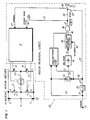
- the electric motor 1 is constructed as a reversible permanent magnet D.C. motor and includes, as is well known and hence has not been illustrated, at least one winding having two ends each of which is connected to a different one of leads 2 and 3 of the electric motor 1.
- the lead 2 is connected by electric conductors 4 and 5 to a positive terminal 8 and to a negative terminal 9, respectively, of a D.C. source which is diagrammatically indicated at 10.
- the lead 3 is connected by electric conductors 7 and 8 to the positive terminal 8 and to the negative terminal 9 of the D.C. source 10, respectively.
- Respective control switches 11, 12, 13 and 14, which are also identified, in that order, by the reference characters A, B, C and D, are interposed in the electric conductors 4, 5, 6 and 7.
- the control switches 11, 12, 13 and 14 may be of any well known construction; for instance, they may be constituted by transistors, electromagnetic relays or the like.
- the control switches 11, 12, 13 and 14 can be switched between their illustrated open positions in which they separate the leads 2 and 3 from the terminals 8 and 9 and their non-illustrated closed positions in which they electrically connect the respective lead 2 or 3 via the respective electric conductor 4, 5, 6 or 7 in which they are incorporated with the respective terminal 8 or 9.
- the closing and/or opening of the switches 11, 12, 13 and 14 occurs in response to respective ultimate command signals which are indicated in Fig. 1 by arrow-headed lines 15, 16, 17 and 18, respectively.
- the lines 15, 16, 17 and 18 may be electric conductors which are directly connected to control inputs of the respective control switches 11, 12, 14 and 14 when the latter are constituted, for instance, by transistors, or they may be representative of more complex arrangements, such as a series of amplifiers, transistors, or the like when the control switches 11, 12, 13 and 14 are constituted, for instance, by electromagnetic relays or the like.
- the lines 15, 16, 17 and 18 constitute respective outputs of a driving or translating circuit 19 which operates in a manner that will be described later and which constitutes a part of a control circuit 20 constructed in accordance with the present invention.
- the operation of the control circuit 20 is determined by original or initial command signals which are supplied to a command input 21 of the control circuit 20.
- These original command signals are of the same type as those supplied to the heretofore known electric motor drive circuits. However, unlike in such known arrangements, these command signals are first processed by the control circuit 20 before reaching the driving or translating circuit 19 to extract therefrom information as to the magnitude of the motor rotation sense reversal to take place and to modify the actuation of the switches 11, 12, 13 and 14 accordingly.
- the original command signals are supplied from the command input 21 through a line 22 to an input of a delay device 23 of a conventional construction which generates lagged versions of the original command signals.
- the original command signals are also supplied through branch lines 24 and 25 to a non-inverting input of a summing arrangement 26.
- another branch line 27 supplies the original command signals to one input of a sign comparison device 28.
- the output signals of the delay device 23, which are the lagged versions of the original command signals are presented at an output line 29 and are supplied therefrom through a branch line 30 to an inverting input of the summing device 26 that then generates an output signal representative of the difference between the original command signals and their lagged versions.
- the lagged versions are fed through another branch line 31 to another input of the sign comparison device 28.
- the device 28 is of any well known construction and is operative for generating a binary signal of a first value (such as binary "0") when the signs of the input signals supplied to the inputs of the sign comparison device 28 through the lines 27 and 31 are in agreement, and of a second value (such as binary "1") when the signs of such input signals supplied through the lines 27 and 31 are different.
- the lagged versions of the original command signals are supplied through an additional branch line 32 to one terminal 33 of a switch 35 whose other terminal 34 is grounded.
- the switch 35 which may be of any known construction, can be switched in response to switching signals between its illustrated position in which it connects a command line 36 with the switch terminal 33, so that the lagged versions of the original command signals propagate through the switch 35 to the command line 36, and its non-illustrated other position in which it connects the command line 36 with the switch terminal 34, so that the command line 36 is grounded.
- the ground may have a binary "0" value attributed to it.
- the operation of the switch 35 is controlled by the output signals of the summing device 26 and of the sign comparison device 28.
- the output signal of the sign comparison device 28 is supplied through a connecting line 37 to one input of a logic element 38 which, in the illustrated design, is constituted by an AND-gate.
- the output signal of the summing device 26 is supplied through another connecting line 39 to an input of a device 40 which is of a well known construction and is operative for producing an absolute value of the output signal of the summing device 26.
- This absolute value is then forwarded through an additional connecting line 41 to a comparator 42 of any well known construction which compares this absolute value with a reference or threshold value that is shown to be supplied to the comparator 42 by a supply line 43.
- the comparator 42 generates a first binary signal (such as a binary "1”) when the aforementioned absolute value exceeds the threshold value, and a second binary signal (such as a binary "0") when the absolute value is below the threshold value.
- the respective binary signal of the comparator 42 is then supplied through a connecting line 44 to another input of the logic element 38.
- the logic element 38 issues at its output 45 a signal of one binary value (such as binary "1" in the above-described situation) if and only if both of the input signals supplied to its inputs through the connecting lines 37 and 44 have the first binary value (i.e. binary "1"), and of the other binary value (such as binary "0") for all remaining combinations of the first and second binary values of the input signals.
- the output signal of the logic element 38 is then used as a control or activating signal for the switching of the switch 35 between its two positions, as indicated by an arrowheaded line 46.
- the line 46 is representative of any known actuating arrangement, in the same manner as discussed before in connection with the switching of the switches 11 to 14.
- the switch 35 is caused to assume its non-ilustrated position in which it connects the command line 36 with the grounded terminal 34 when the output signal of the logic element 38 has the one binary value and its illustrated position in which it connects the command line 36 with the terminal 33 receiving the lagged versions of the original command signals when the output signal of the logic element 38 has the other binary value.
- the output signal of the logic element 38 is also supplied as a dynamic brake flag signal via a branch-off line 47 to one input 48 of the driving or translating circuit 19.
- the command line 36 leads to another input 49 of the driving or translating circuit 19 to supply thereto an intermediate command signal which is then being furnished by the switch 35.
- the driving or translating circuit 19 then generates, on the basis of the dynamic brake flag signal and the intermediate command signal supplied to the inputs 48 and 49 thereof, respectively, the ultimate command signals which appear at the outputs !5, 16, 17 and 18 and which control the positions of the switches 11, 12, 13 and 14, respectively.
- the switch driving or translating circuit 19 will be discussed in some detail later, as will the details of the operation of this particular construction of the circuit 19. At this juncture, it is sufficient to mention that the circuit 19 generates the ultimate command signals in the manner which is depicted in the logic table of Fig. 2. It may be seen there that, so long as the dynamic brake flag is off (i.e.
- the flag signal at the input 48 is a binary "0"
- the switches A, B, C and D (or 11, 12, 13 and 14) are operated in a well-known manner in response to the intermediate command signals which are then constituted by the lagged versions of the original command signals.
- This mode of operation of the driving or translating circuit 19 is well known, as is the circuitry accomplishing this operating mode, so that they need not be addressed in any more detail at this point.
- the switches A, B, C and D are operated such a manner that both ends of the winding of the electric motor 1 are simultaneously connected to one of the terminals 8 and 9 of the electric power source 10 (in the depicted exemplary implementation, to the terminal 9).
- the winding of the electric motor 1 is short-circuited in this situation, and the electric current induced in the winding is dissipated before electric current of a polarity corresponding to the new sense of rotation is supplied from the source 10 to the winding of the electric motor 1.
- the operation of the electric motor 1 during any excessive sense of rotation reversal is accomplished in two steps, with dynamic braking indicated at 51 intervening between energizations of the winding with opposite polarities.
- the speed of rotation of the electric motor 1 is first reduced to zero during the dynamic braking and only then is the electric motor accelerated again to the desired speed of rotation in the opposite sense after the dynamic brake flag has been discontinued.
- the electric motor current exhibits a first spike 52 at the beginning of the dynamic braking and a second spike 53 at the beginning of the rotation in the opposite sense.
- the magnitudes of the electric current spikes 52 and 53 are much smaller than that of the spike 50, each generally corresponding to the start-up spike occurring at the commencement of the operation of the electric motor 1 from standstill to the desired speed in the respective sense of rotation.
- the amount of time during which the electric motor 1 is being dynamically braked is proportional to the desired magnitude if the sense of rotation reversal. Once this dynamic braking time period has elapsed, the new electric current polarity is applied to the winding of the electric motor 1, and the motor 1 accelerates to the desired new operating speed.
- the command input 49 is connected via an electrical connection 54 to an input of an absolute value generating device 55 that has a similar or identical construction as the device 40, and via an electrical connection 56 to a direction discriminator device 57 of a known construction which generates a signal of one binary value (such as binary "1") when the value of the intermediate command signal is at least equal to zero and of the other binary value (such as binary "0") when the value of the intermediate command signal falls below zero.
- the absolute value of the intermediate command signal appearing at the output of the device 55 is supplied through an electrical connection 58 to one input of a comparator 59, while an output signal of a low-frequency oscillator 60 is supplied through an electrical connection 61 to another input of the comparator 59.
- the oscillator 60 is a commonly available sawtooth oscillator which operates at and determines the frequency of the basic pulse width modulation.
- the comparator 59 compares the output signal of the oscillator 60 with the absolute value of the intermediate command signal appearing at the output of the device 55. If the magnitude of the absolute value exceeds the instantaneous magnitude of the sawtooth-shaped output signal of the oscillator 60, then the output signal of the comparator 59 has a binary "1" value; otherwise, it has a binary "0” value. The comparator 59 thus issues pulse-modulated signals whose width is determined by the instantaneous magnitude of the absolute value of the intermediate command signal.
- the output of the comparator 59 is fed through an electrical connection 62 to a data input D of a first flip-flop 63.
- An output signal of a high-frequency oscillator 64 whose frequency is orders of magnitude higher than that of the output signal of the low-frequency oscillator 60 and which is generates a square waveform at its output, is supplied through an electrical connection 65 to a clock input CK of the first flip-flop 63, as well as through an electrical connection 66 to a clock input CK of a second flip-flop 67.
- the dynamic brake flag input 48 of the circuit 19 is supplied through an electrical connection 68 to a resetting input R of the first flip-flop 63.
- An output Q of the first flip-flop 63 is connected by an electrical connection 69 to a data input D of the second flip-flop 67.
- the Q output of the first flip-flop 63 and an output Q of the second flip-flop 67 are connected via respective electric connections 70 and 71 to respective inputs of a NOR-gate 74, while of the first flip-flop 63 and an inverted output Q of the second flip-flop 67 are similarly connected via respective electric connections 72 and 73 to respective inputs of an OR-gate 75.
- the signal supplied to the D input of the flip-flop 63 will appear at the Q output, and its logic inverse at the Q output, of the flip-flop 63 on the rising edge of the clock signal supplied to the CK input of the first flip-flop 63, and propagate in the same manner to the Q and Q outputs of the second flip-flop 67 on the next following rising edge of the clock signal supplied to the CK input of the flip-flop 67.
- the output of the NOR-gate 74 is coupled by respective electric connections 76 and 77 to first inputs of OR-gates 80 and 81, whereas the output of the OR-gate 75 is coupled by respective electric connections 78 and 79 to first inputs of NOR-gates 82 and 83.
- the outputs of the OR-gates 80 and 81 are connected to the lines 17 and 18 leading to the switches 13 and 14, and the outputs of the NOR-gates 82 and 82 are connected to the lines 15 and 16 leading to the switches 11 and 12.
- the output of the direction discriminator device 57 is connected directly through electrical connections 84, 85 and 86 to respective other inputs of the OR-gate 80 and of the NOR-gate 82, and indirectly through electrical connections 84, 87 and 88 via an inverter 89 interposed in the electrical connection 87 to respective other inputs of the OR-gate 81 and of the NOR-gate 83.
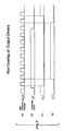
- This causes the switch 11 to be permanently open and the switch 13 to be permanently closed whenever the value of the intermediate command signal on the input 49 of the circuit 19 is zero or more, and the switch 12 to be permanently open and the switch 14 to be permanently closed whenever the value of the intermediate command signal on the input 49 of the circuit 19 is less than zero, as indicated in Figs. 6e to 6h as considered in conjunction with Fig. 6a.
- the first and second flip-flops are in a master-slave relation lengthyship. This results in a situation that is graphically depicted in Figs. 7a to 7d of the drawing for the switches 13 and 11 with the intermediate command signal supplied to the input 49 of the circuit 19 having a negative value and the dynamic brake signal supplied to the input 48 having a binary "0" value. It may be seen that the switch 13 opens before the switch 11 closes as the comparator output signal goes from binary "0" to binary "1", and closes after the switch 11 has been opened as the comparator output signal goes from binary "1" to binary "0". This means that the switches 11 and 13 are never simultaneously closed, which would result in a short-circuit connection between the lines 4 and 6 and thus between the terminals 8 and 9 of the D.C. source 10.
Landscapes
- Engineering & Computer Science (AREA)
- Power Engineering (AREA)
- Stopping Of Electric Motors (AREA)
- Control Of Direct Current Motors (AREA)
Applications Claiming Priority (2)
| Application Number | Priority Date | Filing Date | Title |
|---|---|---|---|
| US96196 | 1987-09-14 | ||
| US07/096,196 US4816726A (en) | 1987-09-14 | 1987-09-14 | Method of and arrangement for controlling and h-bridge electric motor |
Publications (3)
| Publication Number | Publication Date |
|---|---|
| EP0308358A2 true EP0308358A2 (de) | 1989-03-22 |
| EP0308358A3 EP0308358A3 (en) | 1989-10-11 |
| EP0308358B1 EP0308358B1 (de) | 1994-02-09 |
Family
ID=22256270
Family Applications (1)
| Application Number | Title | Priority Date | Filing Date |
|---|---|---|---|
| EP88630162A Expired - Lifetime EP0308358B1 (de) | 1987-09-14 | 1988-09-14 | Methode und Anordnung zur Steuerung eines Elektromotors in H-Brückenschaltung |
Country Status (7)
| Country | Link |
|---|---|
| US (1) | US4816726A (de) |
| EP (1) | EP0308358B1 (de) |
| JP (1) | JP2790819B2 (de) |
| KR (1) | KR0127313B1 (de) |
| AU (1) | AU596939B2 (de) |
| CA (1) | CA1284816C (de) |
| DE (2) | DE3887722T2 (de) |
Cited By (2)
| Publication number | Priority date | Publication date | Assignee | Title |
|---|---|---|---|---|
| EP0553867A3 (en) * | 1992-01-30 | 1994-04-13 | Fujitsu Ltd | Drive circuit for electronic device |
| CN110646018A (zh) * | 2019-09-12 | 2020-01-03 | 东南大学 | 一种低速运放实现的高频电流源惠斯通电桥检测电路 |
Families Citing this family (26)
| Publication number | Priority date | Publication date | Assignee | Title |
|---|---|---|---|---|
| US4816726A (en) * | 1987-09-14 | 1989-03-28 | United Technologies Corporation | Method of and arrangement for controlling and h-bridge electric motor |
| USRE35806E (en) * | 1988-11-16 | 1998-05-26 | Sgs-Thomson Microelectronics S.R.L. | Multipurpose, internally configurable integrated circuit for driving a switching mode external inductive loads according to a selectable connection scheme |
| US5402052A (en) * | 1989-05-25 | 1995-03-28 | International Business Machines Corporation | Inductive current switching system with resonance |
| US5184299A (en) * | 1990-05-31 | 1993-02-02 | General Motors Corporation | Antilock brake system motor speed control |
| DE4028241A1 (de) * | 1990-09-06 | 1992-03-12 | Leica Mikroskopie & Syst | Positionssteuerung |
| US5243522A (en) * | 1990-12-19 | 1993-09-07 | Automotive Products (Usa) Inc. | Electrical control apparatus for control of an automatic transmission apparatus with remote motor controller circuit |
| US5287046A (en) * | 1992-05-13 | 1994-02-15 | International Business Machines Corporation | Method and system for actuator control for direct access storage devices |
| JP3446220B2 (ja) * | 1992-05-21 | 2003-09-16 | ソニー株式会社 | モータ駆動装置 |
| JPH062316U (ja) * | 1992-06-12 | 1994-01-14 | 株式会社ニコン | カメラ及びそのアクセサリーに使用されるモータ駆動装置 |
| US6002225A (en) * | 1992-08-20 | 1999-12-14 | Deutsche Thomson-Brandt Gmbh | Method for the control of a motor |
| US5361022A (en) * | 1993-03-23 | 1994-11-01 | E. F. Bavis & Associates, Inc. | Method and apparatus for electrical dynamic braking |
| KR0160626B1 (ko) * | 1993-05-26 | 1999-01-15 | 김광호 | 슬래드 모터 미끄럼 방지회로 |
| US5642023A (en) * | 1995-01-19 | 1997-06-24 | Textron Inc. | Method and apparatus for the electronic control of electric motor driven golf car |
| US5793175A (en) * | 1995-01-19 | 1998-08-11 | Textron Inc. | Performance event sensing for control of electric motor driven golf car |
| US5838127A (en) * | 1996-12-05 | 1998-11-17 | General Electric Company | Single phase motor for laundering apparatus |
| US6236177B1 (en) | 1998-06-05 | 2001-05-22 | Milwaukee Electric Tool Corporation | Braking and control circuit for electric power tools |
| US6175204B1 (en) * | 1998-11-25 | 2001-01-16 | Westinghouse Air Brake Company | Dynamic brake for power door |
| DE10246520A1 (de) * | 2002-10-05 | 2004-04-22 | Braun Gmbh | Schaltungsanordnung zur Ansteuerung eines oszillierenden Elektromotors |
| JP4039280B2 (ja) * | 2003-03-14 | 2008-01-30 | ミツミ電機株式会社 | モータ駆動回路 |
| TWI281773B (en) * | 2004-02-25 | 2007-05-21 | Delta Electronics Inc | A real-time stopping fan method and structure thereof |
| JP2007115377A (ja) * | 2005-10-24 | 2007-05-10 | Teac Corp | ディスク装置 |
| DE602006013863D1 (de) * | 2005-11-04 | 2010-06-02 | Bosch Gmbh Robert | Verfahren und vorrichtung für einen gelenkbohrer |
| US9555498B2 (en) * | 2005-12-30 | 2017-01-31 | Roger Hirsch | Resistance welding machine pinch point safety sensor |
| JP2007221857A (ja) * | 2006-02-14 | 2007-08-30 | Honda Motor Co Ltd | モータ制御装置 |
| US8552672B2 (en) * | 2010-10-19 | 2013-10-08 | Teknic, Inc. | Method and apparatus to drive two-phase motors from a three-phase bridge |
| DE102012203335A1 (de) * | 2012-03-02 | 2013-09-05 | Robert Bosch Gmbh | Feststellbremse in einem Fahrzeug |
Family Cites Families (12)
| Publication number | Priority date | Publication date | Assignee | Title |
|---|---|---|---|---|
| DE2709627A1 (de) * | 1977-03-05 | 1978-09-07 | Bosch Gmbh Robert | Steuervorrichtung fuer ein elektrisches bauelement, dessen spannung nach dem abschalten verzoegert absinkt |
| GB1600262A (en) * | 1977-11-03 | 1981-10-14 | Lansing Bagnall Ltd | Control circuit for a dc motor |
| US4329630A (en) * | 1980-01-04 | 1982-05-11 | General Electric Company | Single transistor power control circuit for a DC motor washing machine drive |
| JPS56157289A (en) * | 1980-05-01 | 1981-12-04 | Olympus Optical Co Ltd | Braking device for motor |
| AT374638B (de) * | 1981-12-21 | 1984-05-10 | Siemens Ag Oesterreich | Schaltungsanordnung zur erfassung der polaritaet des laststromes in einem gleichstrom-umkehrsteller |
| US4416352A (en) * | 1982-02-17 | 1983-11-22 | Westinghouse Electric Corp. | Elevator system |
| JPS5986498A (ja) * | 1982-11-09 | 1984-05-18 | Seiko Instr & Electronics Ltd | パルス幅変調直流サ−ボモ−タ駆動回路 |
| US4544869A (en) * | 1983-10-05 | 1985-10-01 | Unisen, Inc. | Electronic control circuit for bi-directional motion |
| US4527103A (en) * | 1984-06-08 | 1985-07-02 | General Motors Corporation | Four state DC motor controller |
| US4663575A (en) * | 1986-02-21 | 1987-05-05 | United Technologies Automotive, Inc. | Speed control for a window wiper system |
| US4710686A (en) * | 1986-08-04 | 1987-12-01 | Guzik Technical Enterprises | Method and apparatus for control of current in a motor winding |
| US4816726A (en) * | 1987-09-14 | 1989-03-28 | United Technologies Corporation | Method of and arrangement for controlling and h-bridge electric motor |
-
1987
- 1987-09-14 US US07/096,196 patent/US4816726A/en not_active Expired - Lifetime
-
1988
- 1988-09-12 AU AU22110/88A patent/AU596939B2/en not_active Ceased
- 1988-09-13 CA CA000577192A patent/CA1284816C/en not_active Expired - Lifetime
- 1988-09-14 EP EP88630162A patent/EP0308358B1/de not_active Expired - Lifetime
- 1988-09-14 DE DE3887722T patent/DE3887722T2/de not_active Expired - Lifetime
- 1988-09-14 JP JP63230463A patent/JP2790819B2/ja not_active Expired - Fee Related
- 1988-09-14 DE DE198888630162T patent/DE308358T1/de active Pending
- 1988-09-14 KR KR1019880011848A patent/KR0127313B1/ko not_active Expired - Fee Related
Cited By (4)
| Publication number | Priority date | Publication date | Assignee | Title |
|---|---|---|---|---|
| EP0553867A3 (en) * | 1992-01-30 | 1994-04-13 | Fujitsu Ltd | Drive circuit for electronic device |
| US5604759A (en) * | 1992-01-30 | 1997-02-18 | Fujitsu Limited | Drive circuit for electronic device |
| CN110646018A (zh) * | 2019-09-12 | 2020-01-03 | 东南大学 | 一种低速运放实现的高频电流源惠斯通电桥检测电路 |
| CN110646018B (zh) * | 2019-09-12 | 2021-10-19 | 东南大学 | 一种低速运放实现的高频电流源惠斯通电桥检测电路 |
Also Published As
| Publication number | Publication date |
|---|---|
| AU2211088A (en) | 1989-03-16 |
| JPH01164291A (ja) | 1989-06-28 |
| EP0308358B1 (de) | 1994-02-09 |
| EP0308358A3 (en) | 1989-10-11 |
| AU596939B2 (en) | 1990-05-17 |
| DE3887722T2 (de) | 1994-06-16 |
| KR890005963A (ko) | 1989-05-18 |
| CA1284816C (en) | 1991-06-11 |
| US4816726A (en) | 1989-03-28 |
| KR0127313B1 (ko) | 1998-04-06 |
| JP2790819B2 (ja) | 1998-08-27 |
| DE3887722D1 (de) | 1994-03-24 |
| DE308358T1 (de) | 1989-07-13 |
Similar Documents
| Publication | Publication Date | Title |
|---|---|---|
| EP0308358A2 (de) | Methode und Anordnung zur Steuerung eines Elektromotors in H-Brückenschaltung | |
| EP1768251B1 (de) | Schutzschaltungsanordnung für Permanent-Magnet Synchronmotor im Feldschwächbereich | |
| EP0765027B1 (de) | Stromverlauf zur Reduzierung der Geräusche eines geschalteten Reluktanzmotors | |
| KR960012684A (ko) | 동기모터의 제동방법 및 장치 | |
| EP0739078A3 (de) | Elektromagnetische Rotationsmaschine | |
| WO2010131344A1 (ja) | 電力変換装置および電力変換装置のコンデンサ電圧の制御方法 | |
| US7027315B2 (en) | Circuit arrangement for operating an electrical machine | |
| CA2773830C (en) | Electric machine assembly with fail-safe arrangement | |
| US7804270B2 (en) | Motor start circuit with capacitive discharge protection | |
| CN101005206A (zh) | 用于永磁同步电机弱磁运行的保护电路 | |
| KR20070030236A (ko) | 동기식 전기 모터용 구동 회로 | |
| JP2001268961A (ja) | スイッチトリラクタンスモータ制御方法およびその装置 | |
| JP3286052B2 (ja) | ブラシレスモータの制御回路 | |
| JPH06162891A (ja) | リレー駆動回路 | |
| JPS61135015A (ja) | 開閉器駆動装置 | |
| JP3494664B2 (ja) | Dcブラシレスモータおよび遮断機 | |
| JP4178588B2 (ja) | 誘導電動機の制動方法 | |
| JP3300985B2 (ja) | 遮断機 | |
| JP4234266B2 (ja) | ステッピングモータの駆動回路 | |
| JP3849131B2 (ja) | インバータ装置 | |
| JP2000324877A (ja) | ブラシレスdcモータの駆動回路 | |
| CN116771233A (zh) | 开闭体控制装置 | |
| US11108345B1 (en) | Control circuit for passive braking for DC motor | |
| JP2922716B2 (ja) | インバータ装置の直流制動方法 | |
| JP2002044973A (ja) | 永久磁石モータの制御装置 |
Legal Events
| Date | Code | Title | Description |
|---|---|---|---|
| PUAI | Public reference made under article 153(3) epc to a published international application that has entered the european phase |
Free format text: ORIGINAL CODE: 0009012 |
|
| AK | Designated contracting states |
Kind code of ref document: A2 Designated state(s): DE FR GB IT |
|
| ITCL | It: translation for ep claims filed |
Representative=s name: RICCARDI SERGIO & CO. |
|
| EL | Fr: translation of claims filed | ||
| DET | De: translation of patent claims | ||
| PUAL | Search report despatched |
Free format text: ORIGINAL CODE: 0009013 |
|
| AK | Designated contracting states |
Kind code of ref document: A3 Designated state(s): DE FR GB IT |
|
| 17P | Request for examination filed |
Effective date: 19891115 |
|
| 17Q | First examination report despatched |
Effective date: 19920324 |
|
| GRAA | (expected) grant |
Free format text: ORIGINAL CODE: 0009210 |
|
| AK | Designated contracting states |
Kind code of ref document: B1 Designated state(s): DE FR GB IT |
|
| ET | Fr: translation filed | ||
| REF | Corresponds to: |
Ref document number: 3887722 Country of ref document: DE Date of ref document: 19940324 |
|
| ITF | It: translation for a ep patent filed | ||
| PLBE | No opposition filed within time limit |
Free format text: ORIGINAL CODE: 0009261 |
|
| STAA | Information on the status of an ep patent application or granted ep patent |
Free format text: STATUS: NO OPPOSITION FILED WITHIN TIME LIMIT |
|
| 26N | No opposition filed | ||
| REG | Reference to a national code |
Ref country code: GB Ref legal event code: IF02 |
|
| PG25 | Lapsed in a contracting state [announced via postgrant information from national office to epo] |
Ref country code: IT Free format text: LAPSE BECAUSE OF NON-PAYMENT OF DUE FEES;WARNING: LAPSES OF ITALIAN PATENTS WITH EFFECTIVE DATE BEFORE 2007 MAY HAVE OCCURRED AT ANY TIME BEFORE 2007. THE CORRECT EFFECTIVE DATE MAY BE DIFFERENT FROM THE ONE RECORDED. Effective date: 20050914 |
|
| PGFP | Annual fee paid to national office [announced via postgrant information from national office to epo] |
Ref country code: GB Payment date: 20070809 Year of fee payment: 20 |
|
| PGFP | Annual fee paid to national office [announced via postgrant information from national office to epo] |
Ref country code: DE Payment date: 20070928 Year of fee payment: 20 |
|
| PGFP | Annual fee paid to national office [announced via postgrant information from national office to epo] |
Ref country code: FR Payment date: 20070904 Year of fee payment: 20 |
|
| REG | Reference to a national code |
Ref country code: GB Ref legal event code: PE20 Expiry date: 20080913 |
|
| PG25 | Lapsed in a contracting state [announced via postgrant information from national office to epo] |
Ref country code: GB Free format text: LAPSE BECAUSE OF EXPIRATION OF PROTECTION Effective date: 20080913 |