EP0308621A2 - Arrangement pour la stabilisation d'un système de puissance - Google Patents
Arrangement pour la stabilisation d'un système de puissance Download PDFInfo
- Publication number
- EP0308621A2 EP0308621A2 EP88112125A EP88112125A EP0308621A2 EP 0308621 A2 EP0308621 A2 EP 0308621A2 EP 88112125 A EP88112125 A EP 88112125A EP 88112125 A EP88112125 A EP 88112125A EP 0308621 A2 EP0308621 A2 EP 0308621A2
- Authority
- EP
- European Patent Office
- Prior art keywords
- pss
- phase
- period
- lag
- power
- Prior art date
- Legal status (The legal status is an assumption and is not a legal conclusion. Google has not performed a legal analysis and makes no representation as to the accuracy of the status listed.)
- Granted
Links
Images


Classifications
-
- G—PHYSICS
- G05—CONTROLLING; REGULATING
- G05B—CONTROL OR REGULATING SYSTEMS IN GENERAL; FUNCTIONAL ELEMENTS OF SUCH SYSTEMS; MONITORING OR TESTING ARRANGEMENTS FOR SUCH SYSTEMS OR ELEMENTS
- G05B5/00—Anti-hunting arrangements
- G05B5/01—Anti-hunting arrangements electric
-
- H—ELECTRICITY
- H02—GENERATION; CONVERSION OR DISTRIBUTION OF ELECTRIC POWER
- H02P—CONTROL OR REGULATION OF ELECTRIC MOTORS, ELECTRIC GENERATORS OR DYNAMO-ELECTRIC CONVERTERS; CONTROLLING TRANSFORMERS, REACTORS OR CHOKE COILS
- H02P25/00—Arrangements or methods for the control of AC motors characterised by the kind of AC motor or by structural details
- H02P25/02—Arrangements or methods for the control of AC motors characterised by the kind of AC motor or by structural details characterised by the kind of motor
- H02P25/022—Synchronous motors
- H02P25/024—Synchronous motors controlled by supply frequency
Definitions
- the present invention relates to a power system stabilizer (hereinafter to be briefly called PSS) and more particularly to a PSS for use in an excitation system for a synchronous motor.
- PSS power system stabilizer
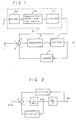
- Fig. 1 is a block diagram of a general excitation system including a prior art PSS as disclosed, for example, in Japanese Patent Publication No. 53-44204.
- 1 denotes an input terminal of a deviation of terminal voltage of an electric motor from its reference voltage
- 2 denotes a PSS
- 3 denotes an input terminal of the PSS
- 4 denotes a damping circuit
- 5 denotes an adder for deducting the output of the damping circuit 4 from the sum total of the deviation from the input terminal 1 and the output of the PSS
- 6 denotes a regulator for controlling an exciter 7 based upon the output of the adder circuit 5
- 7 denotes the exciter controlled by the regulator 6 and supplying field voltage to the motor (not shown).
- Denoted by 2a is a filter circuit for determining the response range of the PSS 2 to the input signal 3, which generally has a transfer function characteristic expressed as Denoted by 2b is a portion for compensating for time-delay of the regulator 6, exciter 7, motor, and the like and is a lead-lag circuit expressed generally by the form of Denoted by 2c is a limiter for limiting the output signal of the PSS 2 so that it has a suitable signal level for the performance of the excitation system shown in Fig. 1 as a whole.
- the deviation in the number of revolutions of the rotor of the motor, deviation in frequency of the terminal voltage of the motor, deviation in the output power of the motor, and the like is generally used.
- the PSS 2 is a control apparatus for providing the adder 5 of the aforesaid excitation system with a properly amplified and compensated auxiliary signal (for example, deviation in number of revolutions of the rotor of the motor) thereby to improve stability of the power system.
- a properly amplified and compensated auxiliary signal for example, deviation in number of revolutions of the rotor of the motor
- Fig. 2 is a block diagram showing linear approximation of fluctuation in a motor in a singlemachine infinite bus system as described, for example, in "THE SOCIETY OF ELECTRICAL COOPERATIVE RESEARCH", Vol. 84, No. 5.
- K1 represents a coefficient of synchronizing torque produced by a motor whose field flux linkage is constant
- K1′ represents a coefficient of synchronizing torque produced by the AVR
- K1 ⁇ represents a coefficient of synchronizing torque produced by the PSS
- D represents a coefficient of damping torque produced by the motor whose field flux linkage is constant
- D′ represents a coefficient of damping torque produced by the AVR
- D ⁇ represents a coefficient of damping torque produced by the PSS.
- the coefficient D′ is liable to take a negative value.
- FIG. 3 is an explanatory diagram showing such behavior.
- the PSS produces damping force D ⁇ acting in opposite direction to the negative damping force.
- the PSS has no object to improve the synchronizing force, and therefore, K1 ⁇ sometimes becomes very small or, in some case, takes a small negative value.
- phase compensating values of the PSS in the first power swing mode and in the second power swing mode that is, the constants in the above mentioned lead-lag circuit, do not always become equal but normally the optimum compensating values are different from each other.
- an object of the present invention is to provide a PSS which will make optimum phase compensation for two power swing modes or more, and which, even in the case where the contents of the multiple power swing modes are changed dependent upon the state of the external disturbance (line fault) of the power system, will automatically make optimum phase compensation and readily produce satisfactory results.
- the PSS comprises detectors for detecting periods of each of the power fluctuation modes and a lead-lag compensation circuit, with fuzzy inference applied thereto, in response to the outputs of the detectors for adjusting the constant in a phase lead-lag circuit of the PSS, whereby the constant in the phase lead-lag circuit of the PSS is adapted to be automatically adjusted, on an on-line basis, responding to the changes in the periods of each of the power swing modes.
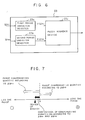
- numeral reference 21 denotes a first period detector in response to the input to a PSS 2 for detecting the period of a first power fluctuation mode
- 22 denotes a second period detector for detecting, similarly to the aforesaid first period detector, the period of a second power fluctuation mode
- 23 denotes a phase lead-lag compensation circuit in response to the outputs of the aforesaid first period detector 21 and second period detector 22 for adjusting the constant in a phase lead-lag circuit in an amplification and phase lead-lag circuit 2b of the PSS.
- Fig. 6 shows internal structure of the phase lead-lag compensation circuit.
- 23a denotes a first period variation detector in response to the output of the aforesaid first period detector 21 for detecting a variation in its period
- 23b denotes a second period variation detector in response to the output of the aforesaid second period detector 22 for detecting, similarly to the above, for detecting variation in its period
- 23c denotes a fuzzy inference device in response to the outputs of the aforesaid first and second period variation detectors 23a, 23b for outputting, through fuzzy inference, a signal to the amplification and phase lead-lag circuit 2b for compensating for the constant in the phase lead-lag circuit of the PSS.
- the torque K1 ⁇ + D ⁇ produced by the PSS is in a direction parallel to the D ⁇ ⁇ (damping torque) axis, and therefrom it is known that if the phase of this vector lags (which means that the vector makes a clockwise turn), the K1 + K1′ + K1 ⁇ component becomes larger by composition of vectors, and if conversely the phase of the PSS leads, the K1 + K1′ + K1 ⁇ component becomes smaller.
- the first and second period detectors 21, 22 output the component of a first power swing mode and the component of a second power swing, respectively, from an actual power waveform.
- the output ⁇ n1 of the first period detector 21 may become as shown by the waveform of the first power swing mode in Fig. 4 and the output ⁇ n2 of the second period detector 22 may become as shown by the waveform of the second power swing mode in Fig. 4.
- These waveforms can be easily obtained by use of fast Fourier transform or the like.
- These are input to the first and second period variation detectors 23a, 23b of the phase lead-lag compensation circuit 23.
- the first and second period variation detectors 23a, 23b deliver to the fuzzy inference device 23c their output ⁇ n1 , ⁇ n2 , respectively, each thereof being of a positive value when ⁇ n1 , ⁇ n2 has a tendency to increase and of a negative value when the same has a tendency to decrease and corresponding in magnitude to the degree of the tendency to increase or decrease.
- the fuzzy inference device 23c makes a judgment as to whether the phase of the PSS should be led or lagged depending upon ⁇ n1 , ⁇ n2 .
- ⁇ n1 is of a negative value, that is, the period of the power swing of the first mode has a tendency to increase and that ⁇ n2 is of a positive value, that is, the period of the power swing of the second mode has a tendency to decrease.
- the above described embodiment two sets of detectors such as the first and second period detectors 21, 22 and the first and second period variation detectors 23a, 23b were used for the first and second power swing modes, there may be provided three sets of detectors for first, second, and third power swing modes, or above.
- the amplification and phase lead-lag circuit 2b that of one-circuit structure was mentioned, it can be of two-circuit structure or above.
- the above embodiment was described as an analog apparatus, it can be a digital apparatus for providing the same effects.
- the PSS is provided with the period detectors and the phase lead-lag compensation circuit with fuzzy inference applied thereto, it has been made possible to make automatic adjustment of the phase lead-lag circuit of the PSS for multiple power swing modes optimally and on the on-line basis. Therefore, such effects are obtained that satisfactory PSS functions are achieved and a turningless-PSS can be produced.
Landscapes
- Engineering & Computer Science (AREA)
- Power Engineering (AREA)
- Physics & Mathematics (AREA)
- General Physics & Mathematics (AREA)
- Automation & Control Theory (AREA)
- Control Of Electric Motors In General (AREA)
- Control Of Ac Motors In General (AREA)
- Supply And Distribution Of Alternating Current (AREA)
- Control Of Eletrric Generators (AREA)
Applications Claiming Priority (2)
| Application Number | Priority Date | Filing Date | Title |
|---|---|---|---|
| JP235615/87 | 1987-09-19 | ||
| JP62235615A JPH07114559B2 (ja) | 1987-09-19 | 1987-09-19 | 電力系統安定化装置 |
Publications (3)
| Publication Number | Publication Date |
|---|---|
| EP0308621A2 true EP0308621A2 (fr) | 1989-03-29 |
| EP0308621A3 EP0308621A3 (en) | 1989-10-18 |
| EP0308621B1 EP0308621B1 (fr) | 1993-01-27 |
Family
ID=16988631
Family Applications (1)
| Application Number | Title | Priority Date | Filing Date |
|---|---|---|---|
| EP88112125A Expired - Lifetime EP0308621B1 (fr) | 1987-09-19 | 1988-07-27 | Arrangement pour la stabilisation d'un système de puissance |
Country Status (4)
| Country | Link |
|---|---|
| US (1) | US4967129A (fr) |
| EP (1) | EP0308621B1 (fr) |
| JP (1) | JPH07114559B2 (fr) |
| DE (1) | DE3877874T2 (fr) |
Cited By (4)
| Publication number | Priority date | Publication date | Assignee | Title |
|---|---|---|---|---|
| WO1995007502A1 (fr) * | 1993-09-10 | 1995-03-16 | Ted Layton Hardiman | Unite de gestion de processus industriels et methode de gestion de processus |
| CN101447670B (zh) * | 2008-05-27 | 2011-01-26 | 中国电力科学研究院 | 一种电力系统稳定器参数整定算法 |
| CN105762817A (zh) * | 2016-05-06 | 2016-07-13 | 国电南瑞科技股份有限公司 | 一种多频段电力系统稳定器pss4b放大倍数整定方法 |
| CN110138297A (zh) * | 2019-05-31 | 2019-08-16 | 东南大学 | 一种永磁同步直线电机速度和电流双闭环控制系统和控制方法 |
Families Citing this family (24)
| Publication number | Priority date | Publication date | Assignee | Title |
|---|---|---|---|---|
| US5079492A (en) * | 1988-03-29 | 1992-01-07 | Teijin Seiki Company Limited | Stability compensating circuit |
| US5292995A (en) * | 1988-11-28 | 1994-03-08 | Yamaha Corporation | Method and apparatus for controlling an electronic musical instrument using fuzzy logic |
| JP2698660B2 (ja) * | 1989-06-12 | 1998-01-19 | 株式会社日立製作所 | マニピュレータの制御方法及び制御装置並びにマニピュレータ装置 |
| US5341454A (en) * | 1989-06-16 | 1994-08-23 | Janome Sewing Machine Co., Ltd. | DC motor control in electronic sewing machine |
| JP2748608B2 (ja) * | 1989-10-31 | 1998-05-13 | 株式会社明電舎 | ファジィ推論による電力力率制御装置 |
| US5206566A (en) * | 1990-03-08 | 1993-04-27 | Matsushita Electric Industrial Co., Ltd. | Access method of actuator and control apparatus therefor |
| US5300876A (en) * | 1990-05-11 | 1994-04-05 | Kabushiki Kaisha Toshiba | Power system stabilizer estimating a power system impedance |
| US5440222A (en) * | 1991-07-15 | 1995-08-08 | Mitsubishi Denki Kabushiki Kaisha | Excitation control apparatus for synchronous machine |
| JP2878873B2 (ja) * | 1991-08-26 | 1999-04-05 | 株式会社東芝 | 電力需要予測制御装置 |
| WO1994001926A1 (fr) * | 1992-07-13 | 1994-01-20 | Sundstrand Corporation | Commande adaptative pour convertisseur de puissance |
| US5703791A (en) * | 1994-02-17 | 1997-12-30 | Hitachi, Ltd. | Electric power system stabilization control apparatus and method thereof |
| JPH08182394A (ja) * | 1994-07-29 | 1996-07-12 | Kumamoto Univ | 電力系統安定化装置 |
| GB9610265D0 (en) * | 1996-05-16 | 1996-07-24 | Univ Manchester | Generator transfer function regulator |
| US5818208A (en) * | 1996-12-19 | 1998-10-06 | Abb Power T&D Company Inc. | Flicker controllers using voltage source converters |
| JP3464384B2 (ja) * | 1998-06-03 | 2003-11-10 | 三菱電機株式会社 | 制御信号処理装置及び制御信号処理装置を用いた電力系統安定化装置 |
| JP3435066B2 (ja) * | 1998-07-31 | 2003-08-11 | 三菱電機株式会社 | 電力系統安定化装置及び電力系統安定化方法 |
| US6711556B1 (en) | 1999-09-30 | 2004-03-23 | Ford Global Technologies, Llc | Fuzzy logic controller optimization |
| JP3795783B2 (ja) * | 2001-09-21 | 2006-07-12 | 三菱電機株式会社 | 電圧安定化制御方法 |
| KR100744892B1 (ko) | 2003-03-28 | 2007-08-01 | 세이코 엡슨 가부시키가이샤 | 공간 광 변조 장치와 이 공간 광 변조 장치를 갖는 프로젝터 |
| EP1852952A1 (fr) * | 2005-02-22 | 2007-11-07 | Kyushu Institute of Technology | Procede de commande de stabilite de systeme et systeme pour systeme d' alimentation electrique |
| CN100418284C (zh) * | 2006-09-04 | 2008-09-10 | 天津大学 | 复合型的电力系统稳定器的实现方法 |
| US7495409B2 (en) * | 2006-10-30 | 2009-02-24 | David Coutu | Method and apparatus for eliminating stall and cogging in multi-phase stepping motors |
| US8483885B2 (en) * | 2008-05-09 | 2013-07-09 | Meidensha Corporation | System stabilizing device |
| CN113862728B (zh) * | 2021-09-30 | 2024-01-09 | 佛山仙湖实验室 | Pem纯水电解制氢的压力控制方法、系统、设备及介质 |
Family Cites Families (10)
| Publication number | Priority date | Publication date | Assignee | Title |
|---|---|---|---|---|
| US3538408A (en) * | 1968-10-01 | 1970-11-03 | Westinghouse Electric Corp | Synchronous motor torque compensator control |
| US3673512A (en) * | 1970-09-22 | 1972-06-27 | Allen Bradley Co | Servo amplifier |
| JPS5344204A (en) * | 1976-10-04 | 1978-04-20 | Kansai Paint Co Ltd | Method of producing photosensitive resin |
| US4080559A (en) * | 1976-11-15 | 1978-03-21 | General Electric Company | Torsional protective device for power system stabilizer |
| JPS55125036A (en) * | 1979-03-20 | 1980-09-26 | Tokyo Shibaura Electric Co | System stabilizer |
| US4438386A (en) * | 1981-09-10 | 1984-03-20 | Westinghouse Electric Corp. | Static VAR generation for transmission line compensation of subsynchronous resonance |
| JPS5973000A (ja) * | 1982-10-19 | 1984-04-25 | Toshiba Corp | 電力系統の安定化装置 |
| US4642541A (en) * | 1983-10-20 | 1987-02-10 | Memorex Corporation | Track following servo for higher density disk files |
| JPS61280714A (ja) * | 1985-06-05 | 1986-12-11 | 三菱電機株式会社 | 電力系統安定化装置 |
| US4741023A (en) * | 1986-12-23 | 1988-04-26 | General Electric Company | On-line test and diagnostic system for power system stabilizer |
-
1987
- 1987-09-19 JP JP62235615A patent/JPH07114559B2/ja not_active Expired - Lifetime
-
1988
- 1988-07-26 US US07/224,458 patent/US4967129A/en not_active Expired - Fee Related
- 1988-07-27 EP EP88112125A patent/EP0308621B1/fr not_active Expired - Lifetime
- 1988-07-27 DE DE8888112125T patent/DE3877874T2/de not_active Expired - Fee Related
Cited By (7)
| Publication number | Priority date | Publication date | Assignee | Title |
|---|---|---|---|---|
| WO1995007502A1 (fr) * | 1993-09-10 | 1995-03-16 | Ted Layton Hardiman | Unite de gestion de processus industriels et methode de gestion de processus |
| US5504672A (en) * | 1993-09-10 | 1996-04-02 | Hardiman; Ted L. | Industrial process controller and method of process control |
| CN101447670B (zh) * | 2008-05-27 | 2011-01-26 | 中国电力科学研究院 | 一种电力系统稳定器参数整定算法 |
| CN105762817A (zh) * | 2016-05-06 | 2016-07-13 | 国电南瑞科技股份有限公司 | 一种多频段电力系统稳定器pss4b放大倍数整定方法 |
| CN105762817B (zh) * | 2016-05-06 | 2018-04-20 | 国电南瑞科技股份有限公司 | 一种多频段电力系统稳定器pss4b放大倍数整定方法 |
| CN110138297A (zh) * | 2019-05-31 | 2019-08-16 | 东南大学 | 一种永磁同步直线电机速度和电流双闭环控制系统和控制方法 |
| CN110138297B (zh) * | 2019-05-31 | 2021-01-05 | 东南大学 | 一种永磁同步直线电机速度和电流双闭环控制系统和控制方法 |
Also Published As
| Publication number | Publication date |
|---|---|
| JPS6481688A (en) | 1989-03-27 |
| DE3877874T2 (de) | 1993-05-19 |
| DE3877874D1 (de) | 1993-03-11 |
| EP0308621B1 (fr) | 1993-01-27 |
| JPH07114559B2 (ja) | 1995-12-06 |
| EP0308621A3 (en) | 1989-10-18 |
| US4967129A (en) | 1990-10-30 |
Similar Documents
| Publication | Publication Date | Title |
|---|---|---|
| EP0308621B1 (fr) | Arrangement pour la stabilisation d'un système de puissance | |
| Lorenz | A simplified approach to continuous on-line tuning of field-oriented induction machine drives | |
| US5698968A (en) | Power system stabilizer for generator | |
| US3968422A (en) | Method and apparatus for the static compensation of reactive power | |
| EP0241920A2 (fr) | Système de commande pour convertisseur à modulation de largeur d'impulsion variable | |
| US5300876A (en) | Power system stabilizer estimating a power system impedance | |
| US3474323A (en) | Electrical control systems with stabilizing control means | |
| US5256944A (en) | Motor speed control method and apparatus with drooping compensation independent of acceleration or deceleration current and time constant of motor | |
| KR100221050B1 (ko) | 비동기 기계를 위한 고정자 자속 평가치를 결정하기 위한 방법 | |
| US4733156A (en) | Power system stabilizing apparatus | |
| US3656048A (en) | Non-linear exciter controller for power system damping | |
| JP3464384B2 (ja) | 制御信号処理装置及び制御信号処理装置を用いた電力系統安定化装置 | |
| US3477014A (en) | Electrical control systems with stabilizing control means | |
| US5150029A (en) | Method and apparatus for controlling the magnetic flux of an induction motor | |
| US5172041A (en) | Method and device for asynchronous electric motor control by magnetic flux regulation | |
| JP3463158B2 (ja) | 同期機用励磁装置 | |
| JPH01129800A (ja) | 同期機の励磁制御装置 | |
| Habibullah | Optimal governor control of a synchronous machine | |
| Hsien et al. | Robust speed control of permanent magnet synchronous motors: design and experiments | |
| JPH1080198A (ja) | 発電機励磁制御装置 | |
| JPH08168177A (ja) | 電力系統安定化装置とそれによる制御方法 | |
| JPH02262843A (ja) | 電力系統安定化装置 | |
| JPH05181503A (ja) | 安定化フィードバック制御方法 | |
| RU2079961C1 (ru) | Устройство для управления электроприводом с фрикционной нагрузкой | |
| SU928300A1 (ru) | Самонастраивающа с система управлени |
Legal Events
| Date | Code | Title | Description |
|---|---|---|---|
| PUAI | Public reference made under article 153(3) epc to a published international application that has entered the european phase |
Free format text: ORIGINAL CODE: 0009012 |
|
| AK | Designated contracting states |
Kind code of ref document: A2 Designated state(s): CH DE FR GB LI SE |
|
| PUAL | Search report despatched |
Free format text: ORIGINAL CODE: 0009013 |
|
| AK | Designated contracting states |
Kind code of ref document: A3 Designated state(s): CH DE FR GB LI SE |
|
| 17P | Request for examination filed |
Effective date: 19891102 |
|
| 17Q | First examination report despatched |
Effective date: 19910920 |
|
| GRAA | (expected) grant |
Free format text: ORIGINAL CODE: 0009210 |
|
| AK | Designated contracting states |
Kind code of ref document: B1 Designated state(s): CH DE FR GB LI SE |
|
| REF | Corresponds to: |
Ref document number: 3877874 Country of ref document: DE Date of ref document: 19930311 |
|
| ET | Fr: translation filed | ||
| PGFP | Annual fee paid to national office [announced via postgrant information from national office to epo] |
Ref country code: SE Payment date: 19930726 Year of fee payment: 6 |
|
| PLBE | No opposition filed within time limit |
Free format text: ORIGINAL CODE: 0009261 |
|
| STAA | Information on the status of an ep patent application or granted ep patent |
Free format text: STATUS: NO OPPOSITION FILED WITHIN TIME LIMIT |
|
| 26N | No opposition filed | ||
| PG25 | Lapsed in a contracting state [announced via postgrant information from national office to epo] |
Ref country code: SE Effective date: 19940728 |
|
| EUG | Se: european patent has lapsed |
Ref document number: 88112125.5 Effective date: 19950210 |
|
| EUG | Se: european patent has lapsed |
Ref document number: 88112125.5 |
|
| REG | Reference to a national code |
Ref country code: GB Ref legal event code: IF02 |
|
| PGFP | Annual fee paid to national office [announced via postgrant information from national office to epo] |
Ref country code: FR Payment date: 20050708 Year of fee payment: 18 |
|
| PGFP | Annual fee paid to national office [announced via postgrant information from national office to epo] |
Ref country code: DE Payment date: 20050721 Year of fee payment: 18 |
|
| PGFP | Annual fee paid to national office [announced via postgrant information from national office to epo] |
Ref country code: GB Payment date: 20050727 Year of fee payment: 18 Ref country code: CH Payment date: 20050727 Year of fee payment: 18 |
|
| PG25 | Lapsed in a contracting state [announced via postgrant information from national office to epo] |
Ref country code: GB Free format text: LAPSE BECAUSE OF NON-PAYMENT OF DUE FEES Effective date: 20060727 |
|
| PG25 | Lapsed in a contracting state [announced via postgrant information from national office to epo] |
Ref country code: CH Free format text: LAPSE BECAUSE OF NON-PAYMENT OF DUE FEES Effective date: 20060731 Ref country code: LI Free format text: LAPSE BECAUSE OF NON-PAYMENT OF DUE FEES Effective date: 20060731 |
|
| PG25 | Lapsed in a contracting state [announced via postgrant information from national office to epo] |
Ref country code: DE Free format text: LAPSE BECAUSE OF NON-PAYMENT OF DUE FEES Effective date: 20070201 |
|
| REG | Reference to a national code |
Ref country code: CH Ref legal event code: PL |
|
| GBPC | Gb: european patent ceased through non-payment of renewal fee |
Effective date: 20060727 |
|
| REG | Reference to a national code |
Ref country code: FR Ref legal event code: ST Effective date: 20070330 |
|
| PG25 | Lapsed in a contracting state [announced via postgrant information from national office to epo] |
Ref country code: FR Free format text: LAPSE BECAUSE OF NON-PAYMENT OF DUE FEES Effective date: 20060731 |