EP0308882B1 - Plate-forme pour échafaudages - Google Patents
Plate-forme pour échafaudages Download PDFInfo
- Publication number
- EP0308882B1 EP0308882B1 EP88115452A EP88115452A EP0308882B1 EP 0308882 B1 EP0308882 B1 EP 0308882B1 EP 88115452 A EP88115452 A EP 88115452A EP 88115452 A EP88115452 A EP 88115452A EP 0308882 B1 EP0308882 B1 EP 0308882B1
- Authority
- EP
- European Patent Office
- Prior art keywords
- corner
- scaffold
- floor part
- floor
- edge
- Prior art date
- Legal status (The legal status is an assumption and is not a legal conclusion. Google has not performed a legal analysis and makes no representation as to the accuracy of the status listed.)
- Expired - Lifetime
Links
Images




Classifications
-
- E—FIXED CONSTRUCTIONS
- E04—BUILDING
- E04G—SCAFFOLDING; FORMS; SHUTTERING; BUILDING IMPLEMENTS OR AIDS, OR THEIR USE; HANDLING BUILDING MATERIALS ON THE SITE; REPAIRING, BREAKING-UP OR OTHER WORK ON EXISTING BUILDINGS
- E04G1/00—Scaffolds primarily resting on the ground
- E04G1/15—Scaffolds primarily resting on the ground essentially comprising special means for supporting or forming platforms; Platforms
- E04G1/154—Non-detachably fixed and secured connections between platform and scaffold
-
- E—FIXED CONSTRUCTIONS
- E04—BUILDING
- E04G—SCAFFOLDING; FORMS; SHUTTERING; BUILDING IMPLEMENTS OR AIDS, OR THEIR USE; HANDLING BUILDING MATERIALS ON THE SITE; REPAIRING, BREAKING-UP OR OTHER WORK ON EXISTING BUILDINGS
- E04G1/00—Scaffolds primarily resting on the ground
- E04G1/15—Scaffolds primarily resting on the ground essentially comprising special means for supporting or forming platforms; Platforms
-
- E—FIXED CONSTRUCTIONS
- E04—BUILDING
- E04G—SCAFFOLDING; FORMS; SHUTTERING; BUILDING IMPLEMENTS OR AIDS, OR THEIR USE; HANDLING BUILDING MATERIALS ON THE SITE; REPAIRING, BREAKING-UP OR OTHER WORK ON EXISTING BUILDINGS
- E04G1/00—Scaffolds primarily resting on the ground
- E04G1/15—Scaffolds primarily resting on the ground essentially comprising special means for supporting or forming platforms; Platforms
- E04G1/152—Platforms made of metal or with metal-supporting frame
-
- E—FIXED CONSTRUCTIONS
- E04—BUILDING
- E04G—SCAFFOLDING; FORMS; SHUTTERING; BUILDING IMPLEMENTS OR AIDS, OR THEIR USE; HANDLING BUILDING MATERIALS ON THE SITE; REPAIRING, BREAKING-UP OR OTHER WORK ON EXISTING BUILDINGS
- E04G1/00—Scaffolds primarily resting on the ground
- E04G1/15—Scaffolds primarily resting on the ground essentially comprising special means for supporting or forming platforms; Platforms
- E04G2001/158—Platforms supported by spigots which engage through holes in the platform
Definitions
- the invention relates to a corner floor part for bridging non-parallel limited running and work area areas of scaffolding, which are composed of several fields, the horizontally extending axes or the like for fitting to angled building walls. are inclined to each other, which is arranged at least on one side supported on a support bar of the scaffolding in the corner area forming a continuous running and working surface.
- Scaffolding must be set up around or at right angles, around rounded or polygonal building and container walls, or inside, in order to work on the walls, wall surfaces, installations, equipment or the like.
- a scaffolding covering which contains a corner plank in order to create a safe corner formation when guiding scaffolding around building corners if these corners are rectangular.
- a corner plank was provided, which had several trapezoidal wooden boards and has attached sheet metal caps. These have hollow rivets, which are inserted over the locating pins of scaffolding bars.
- the corner plank is used in a corner in the usual way.
- the corner plank rests securely on the support structure on two scaffolding bars running at right angles to each other against horizontal displacement - but not against lifting off. It has no hooks to hang in and no freely attachable, thinly shaped end as in the invention.
- Adaptation to different building shapes, forced lifting safeguards and, above all, large working widths of the scaffolding covering in the corner area are not provided.
- the problems associated with wood are not taken into account in this corner screed for a scaffold.
- US Pat. No. 3,250,345 shows a scaffold with the above-described, in principle similar, but trapezoidal scaffold floor parts, in which all surface elements lie in the running surface and which can only be assembled according to the angle of the respective trapezoidal part. It is precisely this that is not provided in the invention.
- U.S. Patent 3,265,156 shows platform means with adjustable angle arrangements.
- the principle of the semicircular connection is used.
- One element has a concave and the other element has a convex end, which can interlock accordingly.
- Such special scaffolding elements can also be used to form a platform around round towers or the like. Such is after the However, the invention is not exactly desirable because the usual scaffold base parts of rectangular shape are to be used and the corner areas are to be formed by special elements suspended on one side with hook claws, the other end of which rests on the running surface of the adjacent scaffold base part or is supported in some other way on the scaffold. Such is not apparent from this American patent.
- the invention is intended to avoid such special elements for the entire scaffolding because they are expensive and because standard scaffolding floors can be used for most areas of all levels of the scaffolding and, above all, should be used for storage and transport reasons in addition to the price reasons. Only in areas where a straight connection is not possible is, either very simply designed corner scaffold floor elements, as shown in FIGS. 1 and 2 of the figure description below, or elements as shown in the other drawings, and which have an additional pivoting part, are used. This is not possible with the known solution discussed above.
- corner floor parts are to be designed in such a way that they allow the gaps existing due to different angles to be bridged in different structures, the bridging piece being adjustable in angle twice, namely in Area of both connecting edges should be supported and not as in the construction according to the GDR patent, in which a rotating plate is provided at the end of a special scaffold floor part.
- the European patent EP-A-0 214 345 shows an extendable bridge with a railing. It is not suitable for corner scaffolding.
- the invention has for its object to design corner floor parts of the type mentioned above so that they can be used in existing scaffolding systems, secured with simple means and easily bridged the respective corner and are adaptable to the respective purpose and designed for bridging corner areas of different angles are suitable with the largest possible tread.
- the corner floor part for scaffolding also on different building walls that are not at right angles to each other and / or rounded has an outer boundary which takes a course which corresponds to the positions of the vertical stems of the adjacent scaffolding fields in the main use positions, is at least approximately adapted to the full working width of the scaffolding days, is straight, kinked or rounded and also outside the straight connecting line of the two outermost the scaffolding parts of the adjoining scaffolding fields are located on the support points of the corner floor part and contains a floor pan, which is provided on one side in the region of its hooking edge with hook-in means preventing it from lifting off, hooking claws or hook-in double prisms of this hooking edge being fastened on the outside to a support leg bent into the vertical and the support leg at its lower end has a lift-prevention leg bent outwards in the horizontal direction , which is in the suspended state under the horizontally extending support bar on which the suspension means engage, and where either the other supporting edge
- a suitable scaffold floor part is equipped with hanging means and is firmly and securely attached on one side by a suitable pivoting movement, the two other important edge areas can be designed and supported according to the respective needs.
- corner floor parts in standard solutions for simple right-angled corners with a simple support and pin protection against lateral displacement, it may be sufficient, but not automatically when inserting against lifting secure, especially if additional lifting safeguards are to be attached.
- the present invention provides greater security, especially with slight adaptation to different angles and / or different conditions, and the corner base part, which is suspended on one side and secured against lifting, and is placed on the other side with a suitable course of the outer edge.
- the second partial variant according to the invention of the features of the main claim realizes many of the advantages also realized in connection with the first solution variant.
- the rigid connection because of the rigid connection, it is structurally more complex, but it also offers smooth, continuous toe board surfaces in the corner area thanks to the hanging means provided on both edges, thus avoiding small stumbling stages. It also has defined support points that make the static conditions clear and clear and allows both small and large angles for the corner floor part.
- edge areas should also be included in the inventive configurations. These edge designs are in turn - albeit only partially - related to the pivoting of the components.
- a simple solution is designed with the same suspension means, such as with more complicated scaffolding floor parts, for a certain angular range without replacement or folding parts. It can also be provided with a curb-like, edged edge to prevent parts or people from sliding off in the outdoor area. In a variant, especially for larger angles close to 90 °, it is expedient to provide folding parts which bridge the respective remaining area.
- the invention creates according to claim 1 suitable instructions for practically all cases that show different ways for different needs within the same basic concept.
- the outermost point of the basic element is placed in such a way that when swiveling around the central point of the respective inside corner of the scaffold, the most inwardly projecting part of the outer supporting element can just be swiveled past the outer corner.
- the part that is then no longer free of falls, to be covered, is expediently covered by a folding part, which can additionally be equipped with an edged edge.
- This remaining surface part is expediently pivoted with a vertical pin and lies with its compensating surface under the main surface of the scaffold base part.
- the support end resting on the other rectangular scaffold floor is expediently equipped with a downward-pointing edge-supporting leg, which on the one hand enables the scaffold floor part to be secured in a secure position and on the other hand allows trip elements to be tripped over on trusses which, because of their frame design, lie above the suspension means of the scaffold floors Cross elements require.
- a slightly higher scaffolding base part with a tripping-free edge support leg can also be used for scaffolding that is made up of individual elements with shoes, push-on wedges and perforated fastening disks because the elevation is only a few mm.
- the same scaffolding floor parts can be used for different scaffolding systems, provided that only the hanging means on one side are the same. This is particularly the case with upwardly open U-rails in which hooking claws are hooked. In this case, conveniently simply angled lifting prevention legs grip from below when swiveling in below.
- the rigid connection can be formed with guide edge legs that can be pushed into one another and / or with one or more pitch circle elongated hole sliding connections.
- the guide edge legs are also the toe board limit and allow a secure, rigid connection with a large support base, which with a wider internal pitch circle slot together forms a stable connection of the two sub-elements.
- a guide edge leg is formed in the sliding part with deformed point contact elevations. Such characteristics do not reduce the stability, but ensure safe wearing even in rough operation.
- the scaffolding floor parts of both design variants of the invention can be equipped with the attack means that match the respective scaffolding system.
- hooks, clamps, claws and claws come into consideration.
- the attack means are designed as beads or prisms or as double claws, double hooks, double beads or double prisms, which can also be designed according to claim 11
- the scaffold 10 according to FIG. 1 has stems 11 which are connected by transverse elements and conventional corner connections and railing rods 16. Rectangular scaffolding floors 12 hang with their hooking claws 13 in upwardly open U-bolts 14, each of which extends between two stems 11 in a known manner.
- the stems 11 stand on the floor with feet 15.
- two scaffold fields A and B are set up at an angle of 90 ° to one another and are provided here with only one scaffold floor level, for example.
- the corner area C must be bridged and has diagonally extending railing bars 16 and a corner base part 117, which has on one edge a hanging edge 18 with hanging claws 13 with which it is suspended in the upwardly open U-bolts 14 in this edge area.
- the corner base part 17/117 is designed differently according to the respective purpose according to the following figures.
- Fig. 2 shows a simple corner base part 17, which is suitable for bridging corner areas up to 45 °. It is made from a uniform, non-slip sheet metal part and has a cut that has the usual width dimension GB of a usual scaffolding floor field width on its hanging edge 18. It is laterally limited in its first area by side sections 19.1 and 19.2 which adjoin at right angles. Section 19.2 is so long that in the frame scaffold shown here, which has stems 11.1 and 11.2 standing next to one another, it still extends to the scaffold floor 12.2. There it has a support edge 20 cut off at an angle of 45 °. As can be seen from FIG. 8, this is at an angle downward beveled edge leg 21, which leads to a lower free distance H, so that the corner bottom part 117 lies above the lower cross-connecting tube 22 of the stems 11 of a frame when it is suspended.
- the fourth boundary edge 23 extends from an outer corner point 24 of the support edge 20 to a corner point 25 of the side section 19.1.
- the position is chosen so that the handle 11.3 is not hindered by the boundary edge 23 in other pivot positions when the angles become smaller. Larger but also smallest angles can easily be bridged with a simple, suitably cut and slightly bent sheet metal part.
- the outer edges, which are formed by the side section 19.1 and the boundary edge 23, can be provided with an upwardly projecting, beveled leg, which takes over the function of a toe board to prevent lateral sliding.
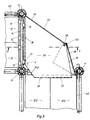
- the exemplary embodiment dealt with in FIGS. 3 to 7 shows a corner base part 117 of the same design.
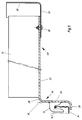
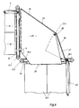
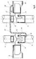
- the hanging area 26 is shown in FIG. 5.
- the bottom plate 27, for example 3 to 5 mm thick, is provided with an edge 28 on its edge 28 which forms the hanging edge 18 Support leg 29, which is bent downward at right angles, in front of which the hook-in claws 13 are welded, which rest on the upper rounded edges 14.1 of the U-support bar 14.
- the support leg 29 is dimensioned so long that it has an outwardly projecting, again in the horizontal bent lifting prevention leg 30, the position and length of which are dimensioned such that it is at a slant from above in its final horizontal position a few mm below the lower edge of the upwardly open U-bracket 14 is, as illustrated in FIG. 5, so that the corner base part 117 cannot tilt. Similar designs are provided on all corner floor parts to allow hanging and to prevent lifting and tipping.
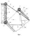
- 3 and 4 in contrast to that according to FIG. 2, is designed with a slightly different outline because it is suitable for bridging larger angles up to 90 °, but also allows bridging small angular ranges.
- the side section 19.2 is placed at an angle ⁇ of 135 °, so that it passes the stems in a suitable manner for all scaffolds in question, even when two stems are next to one another.
- the support edge 20 with your Edge leg 21 extends here to the hooking edge 18 at an angle of 90 ° and is designed further outward so that it rests on the scaffolding floor 12.2 lying around the corner.
- the boundary edge 23 is straight here at an angle of 45 ° so that the outermost corner point 125 is such that the supports 11 in question, together with their accessories located in the corresponding plane, can be swiveled past. It is provided with an upturned curb-like shoulder leg 35. This region of the boundary edge 23, which is provided with shoulder flanges 35, is adjoined by a straight section 36, which is pivoted further inward and without a shoulder limb and to which a pivoting part 37 is assigned.
- the pivoting part 37 allows - as can be seen from FIGS. 3 and 4 - for different angular positions an optimal bridging of the rest of the edge area, because for example at angular positions of only 45 ° according to FIG. 4 the straight section 36 lies in the middle of the surface.
- the pivoting part 37 has an upwardly projecting flange arm 38 and is articulated with the aid of a continuous joint 39 on the base plate 27, as can be seen from FIGS. 3 to 5, below.
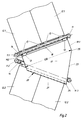
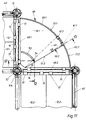
- FIGS. 6 and 7 shows the same parts. Only here are frame structures with two stems 11.1 and 11.2 - as in Fig. 2 - provided. Design, location and function are, however, the same and the two phases of use are shown at 45 ° and at 90 ° with the respective swivel position of the swivel part 37, whereby it can be seen even more clearly how the end 38.1 of the end 38.1 on the actual toe board 40 Main scaffold connects.
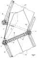
- FIG. 9 shows a variant corresponding to FIGS. 3 and 4, in which the swivel part 41 is longer and its pivot point 42 lies directly on the outer corner of the hanging edge 18.
- a sliding joint 43 with a partially circular elongated hole secures the connection.
- Such a solution may be suitable for certain constructions and angular ranges.
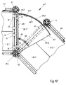
- FIGS. 10 to 14 show a further exemplary embodiment of a scaffold floor part which is designed as a corner floor part 47.
- This corner base part 47 differs from those previously dealt with in that it is composed of two circular segments of sheet metal. These lie one above the other in the overlap area 49.
- Each of these sub-elements 50.1 and 50.2 has an external hanging edge 48.1 and 48.2.
- these are also formed with support legs 29 and 29.2. Both support legs have hooking claws 13 which match the scaffolding system and are fastened in a suitable arrangement.
- the support leg 29 of the larger sub-element 50.1 has a lifting-prevention leg 30 and is hung in the same manner as described above.
- the support leg 29.2 is designed without a lift-prevention leg, so that the corner base part 47 can be pivoted in the manner described above and supported on both sides on the hanging claws 13 on the edges 14.1 of U-support bars 14.
- the two sub-elements 50.1 and 50.2 are each closed off by an outer boundary 51.1 and 51.2 running in the form of a part circle.
- the center of these partial circles is the center 52 of the stem 11.4 lying in the corner, as illustrated in FIGS. 10 and 11, because in this scaffolding system the pivoting when scaffolding on non-straight facades or the like is in each case about the center of one Handle 11.4 between two scaffolding fields and thereby the corner arrangement is built up so that the corner floor part can be hooked in appropriately. If you use scaffolding systems in which two stems or the stems of two frames are close together, a suitable center must be defined in their vicinity for the design of the corner floor part.
- the outer sliding and rigid connection is simultaneously formed with the flange leg 60 of the corner base part 47.
- a flange leg 60.1 or 60.2 corresponding to the rest of the scaffolding system and the safety, is formed on both outer elements 50.1 and 50.2 on the outer area, as is also shown in FIGS. 12 to 14.
- the sub-element 50.2 below is provided with an outer flange 60.2. This is equipped at the top with overlapping legs 61.1 and 61.2 which hold the sliding connection and which reach the inside of the inner flange leg 60.1 from above. So that there is a smooth sliding connection, support knobs 62.1 and 62.2 are embossed from the surface against the flange leg 60.1, so that there are two point-like systems.
- the two overlapping legs 61.1 and 61.2 are at a small angular distance, as is shown in particular in FIG. 11, so that they still securely engage both on the flange leg 60.1 in the smallest overlap region 49. If the corner base part 47 is pivoted further together due to a larger or smaller angle between the scaffolding fields, as is possible up to the end position shown in FIG. 10, the support knobs 62.1 and 62.2 lie completely in the vicinity of the hanging edge 48.1. Then the overhead element 50.1 is pivoted so far over the element 50.2 that its outer end 63 lies over the scaffolding floors 12.2 of the adjacent field, as shown in FIG. 10.
- This arrangement which appears somewhat more complex in terms of execution, creates clear support conditions, but requires a good, rigid and long, securely slidable connection of the components to one another so that they can be adapted to the needs of the construction industry over many years. It does not make use of the principle of support on the neighboring scaffolding floors. It shows a clear toe board boundary that always extends beyond the straight corner railing and always has a closed toe leg arrangement over the entire length.
- the connecting means or hooking means for connecting the corner base part to the support bolts or the like can also have other shapes and can be designed as hooks, eyelets or beads, prisms or other rear grip profiles. They can also be designed as double claws, double hooks, double beads or double prisms or the like, as are usually used for the respective scaffolding system and how they correspond to the receiving space and the associated fastening means, which ensure that the contact forces are supported and prevents lifting becomes, For example, by transverse components that are so close to the hanging means after assembly that they can no longer be lifted out of the secured position of use. 15, double hook-in prisms 75 can be fastened to the support leg 29, which can be formed, for example, from a sheet metal profile that has been bent several times, as can be seen in FIG. 15.
- the hook-in double prism 75 is constructed symmetrically to the horizontal center 76 and has a recess 77.1 or 77.2 on each side, the lower 77.1 of which is intended as a hook-in recess for resting on the edge 14.1 of the U-bracket 14.
- the securing part 78.1 projecting downward has an approximately triangular shape. Its lower edge 82 lies by the amount 83 below the edge 14.1 of the support bar 14.
- the outer boundary wall 79 is vertical and merges into an upper securing part 78.2, which is also approximately triangular in shape.
- a scaffold base part is designed as a corner base part (117) and has a possibly multi-part base plate (27), on which at least one support leg (29) is angled, the hanging claws (13) or the like. wearing.
- a support leg has a lower lift-prevention leg (30) which extends under the U-support bar (14) in the hanging position. It bridges a wide range of angles between other scaffolding floors and can have a swivel part (37) to compensate.
- the actual corner base part (117) can be equipped with a flange leg (35).
- the swivel part (37) can have a flange leg (38). Two sub-elements can be pivotally and rigidly connected to one another.
Landscapes
- Architecture (AREA)
- Engineering & Computer Science (AREA)
- Mechanical Engineering (AREA)
- Civil Engineering (AREA)
- Structural Engineering (AREA)
- Ladders (AREA)
- Movable Scaffolding (AREA)
- Revetment (AREA)
- Load-Engaging Elements For Cranes (AREA)
- Professional, Industrial, Or Sporting Protective Garments (AREA)
- Stringed Musical Instruments (AREA)
- Acyclic And Carbocyclic Compounds In Medicinal Compositions (AREA)
- Pharmaceuticals Containing Other Organic And Inorganic Compounds (AREA)
- Gloves (AREA)
- Saccharide Compounds (AREA)
- Forms Removed On Construction Sites Or Auxiliary Members Thereof (AREA)
- Assembled Shelves (AREA)
- Heat Treatment Of Strip Materials And Filament Materials (AREA)
- Farming Of Fish And Shellfish (AREA)
- Electric Cable Installation (AREA)
- Earth Drilling (AREA)
Claims (11)
- Partie de plancher d'angle pour relier des domaines de surfaces de marche et de travail limités non parallèlement d'échafaudages qui sont constitués par plusieurs travées, dont les axes horizontaux sont inclinés les uns vers les autres pour le montage de l'échafaudage sur des murs de bâtiment formant des angles ou analogues, qui est agencée en étant soutenue au moins d'un côté sur une traverse porteuse de l'échafaudage et en formant dans le domaine d'angle une surface de marche et de travail continue, caractérisée en ce que, pour le montage de l'échafaudage même sur des murs de bâtiment différents, qui ne s'étendent pas perpendiculairement l'un par rapport à l'autre et/ou qui sont arrondis, la partie de plancher d'angle (17,117) comporte une limitation externe (19.1 ; 23) qui présente une étendue qui, dans les positions principales d'utilisation, correspond aux positions des montants verticaux des travées d'échafaudage voisines, qui est sensiblement adaptée à la pleine largeur de travail de l'étage d'échafaudage, qui est rectiligne, angulaire ou arrondie et qui s'étend également à l'extérieur de la ligne de liaison rectiligne des deux points d'appui les plus externes de la partie de plancher d'angle qui sont situés sur les parties d'échafaudage des travées d'échafaudage voisines et qui contient une tôle de plancher (27) qui est munie d'un côté dans le domaine de son arête d'accrochage (18) de dispositifs d'accrochage empêchant un soulèvement, dans laquelle des griffes d'accrochage (13) ou des doubles prismes d'accrochage (75) de cette arête d'accrochage sont fixés du côté extérieur sur un bord porteur (29) recourbé à la verticale et le bord porteur (29) présente à son extrémité inférieure un bord antisoulèvement (30) recourbé vers l'extérieur à l'horizontale, qui, à l'état accroché, est situé sous la traverse porteuse (14) qui s'étend horizontalement et sur laquelle s'accrochent les dispositifs d'accrochage, et dans laquelle l'autre arête de soutien (20) de la partie de plancher d'angle s'appuie à plat sur le plancher d'échafaudage (12.1) voisin, ou bien la partie de plancher d'angle (47) est formée par deux éléments partiels de tôle de plancher (50.1 et 50.2) munis chacun d'une arête d'accrochage (18) comportant des dispositifs d'accrochage (griffes d'accrochage 13 ou doubles prismes d'accrochage 75), qui se déplacent partiellement l'un sur l'autre et qui sont reliés l'un à l'autre de manière pivotable et rigide en flexion (60,61 ; 53, 54) autour d'un centre (point central 52) situé de manière appropriée pour la position des planchers d'échafaudage voisins (12 ; 12.2) et dans laquelle l'étendue de la surface d'une tôle de plancher, éventuellement avec une partie pivotante supplémentaire, ou des deux éléments partiels de tôle de plancher s'étend aussi au-delà de la ligne de liaison des points d'appui les plus externes de la partie de plancher d'angle d'une manière qui correspond à l'angle maximal qui doit être recouvert.
- Partie de plancher d'échafaudage selon la revendication 1, caractérisée en ce que, dans le cas d'échafaudages comportant des montants (11) reliés au cadre d'échafaudage par des liaisons transversales (22), la partie de plancher d'angle (17, 117) s'étend au-dessus de la liaison transversale (22) de la partie de cadre supérieure appliquée et présente au niveau de son extrémité d'appui un bord (21) recourbé vers le bas, de préférence de manière arrondie, d'une manière qui correspond à l'épaisseur de la liaison transversale (22).
- Partie de plancher d'échafaudage selon au moins l'une des revendications précédentes, caractérisée en ce que la partie de plancher d'angle (117) présente une partie pivotante (37) reliée de manière à pouvoir pivoter au-dessous de manière articulée, dont la position la plus large est agencée de manière à correspondre au pivotement sur le domaine d'angle qui doit être recouvert.
- Partie de plancher d'échafaudage selon au moins l'une des revendications précédentes, caractérisée en ce que la partie de plancher d'angle (17, 117) présente sur son côté externe un bord (35) qui fait saillie vers le haut.
- Partie de plancher d'échafaudage selon au moins l'une des revendications précédentes, caractérisée en ce que la partie pivotante (37) présente un bord (38).
- Partie de plancher d'échafaudage selon au moins l'une des revendications précédentes, caractérisée en ce que l'arête de limitation de la partie de fond d'angle fixe (117) s'étend jusqu'à un point d'angle (125) qui est situé de telle sorte que, dans la position de pivotement moyenne des deux éléments d'échafaudage l'un par rapport à l'autre d'environ 45°, il est voisin du montant (11) du domaine d'échafaudage sur lequel s'appuie l'arête de soutien (20) et la section rectiligne (36) s'étend depuis le point d'angle (125) de telle manière que, dans le pivotement de 90° (figure 3) entre elle et le montant (11) situé à l'extérieur, elle laisse un petit espace libre destiné à recevoir le bord (38) de la partie pivotante (37).
- Partie de plancher d'échafaudage selon la revendication 1, caractérisée en ce que les limitations externes (51.1, 51.2) des deux éléments partiels (50.1,50.2) sont en forme d'arcs de cercle.
- Partie de plancher d'échafaudage selon la revendication 7, caractérisée en ce que la liaison rigide en flexion est formée par des bords de guidage pouvant coulisser l'un dans l'autre (60.1, 60.2) et/ou par au moins une liaison par coulisseau et trou oblong en arc de cercle (53, 54).
- Partie de plancher d'échafaudage selon la revendication 8, caractérisée en ce qu'un bord de guidage (60.2) muni de protubérances de contact par point formées par déformation (boutons d'appui 62.1,62.2) est formé dans la partie coulissante.
- Partie de plancher d'échafaudage selon la revendication 1, caractérisée en ce que les dispositifs d'attaque sont sous forme de renflements ou de prismes ou de doubles griffes, de doubles crochets, de doubles renflements ou de doubles primes.
- Partie de plancher d'échafaudage selon la revendication 2 ou 10, caractérisée en ce que l'espace intermédiaire (80) entre le domaine supérieur des dispositifs d'accrochage et un tube de liaison transversale (22, 81) ou analogue qui s'étend entre les montants (11) est plus petit que la hauteur d'empiétement (valeur 83) des dispositifs d'accrochage.
Priority Applications (1)
| Application Number | Priority Date | Filing Date | Title |
|---|---|---|---|
| AT88115452T ATE100171T1 (de) | 1987-09-23 | 1988-09-21 | Geruestbodenteil. |
Applications Claiming Priority (2)
| Application Number | Priority Date | Filing Date | Title |
|---|---|---|---|
| DE3731945 | 1987-09-23 | ||
| DE3731945 | 1987-09-23 |
Publications (3)
| Publication Number | Publication Date |
|---|---|
| EP0308882A2 EP0308882A2 (fr) | 1989-03-29 |
| EP0308882A3 EP0308882A3 (en) | 1989-07-26 |
| EP0308882B1 true EP0308882B1 (fr) | 1994-01-12 |
Family
ID=6336629
Family Applications (1)
| Application Number | Title | Priority Date | Filing Date |
|---|---|---|---|
| EP88115452A Expired - Lifetime EP0308882B1 (fr) | 1987-09-23 | 1988-09-21 | Plate-forme pour échafaudages |
Country Status (8)
| Country | Link |
|---|---|
| EP (1) | EP0308882B1 (fr) |
| JP (1) | JP2721196B2 (fr) |
| AT (1) | ATE100171T1 (fr) |
| AU (1) | AU609880B2 (fr) |
| DE (1) | DE3887051D1 (fr) |
| ES (1) | ES2050133T3 (fr) |
| FI (1) | FI87679C (fr) |
| NO (1) | NO173460C (fr) |
Families Citing this family (15)
| Publication number | Priority date | Publication date | Assignee | Title |
|---|---|---|---|---|
| JPH0748876Y2 (ja) * | 1990-04-11 | 1995-11-08 | 鹿島建設株式会社 | 枠組足場交差部の渡り板 |
| ES2068136B1 (es) * | 1993-05-04 | 1998-01-16 | Ulma S Coop | Andamio multidireccional perfeccionado. |
| AUPM644294A0 (en) * | 1994-06-23 | 1994-07-14 | Drm Pty Ltd | Scaffolding assembly |
| ATE245242T1 (de) * | 1995-03-31 | 2003-08-15 | Layher W Vermogensverw Gmbh | Gerüst |
| FR2748510B1 (fr) * | 1996-05-13 | 1998-08-14 | Altrad Dev | Support d'angle pour echafaudage |
| FR2781515B1 (fr) * | 1998-07-21 | 2000-10-13 | Entrepose Echafaudages | Element de plancher d'echafaudage |
| JP5597348B2 (ja) * | 2008-03-24 | 2014-10-01 | 日鐵住金建材株式会社 | 隙間塞ぎ材及び枠組足場 |
| JP5996890B2 (ja) * | 2012-03-09 | 2016-09-21 | 日綜産業株式会社 | 足場装置 |
| WO2016079372A1 (fr) * | 2014-11-21 | 2016-05-26 | Fast Beam Oy | Agencement d'échafaudage |
| DE202017000413U1 (de) * | 2017-01-25 | 2017-03-07 | Artinger Gerüstbau e.K. | Längenausgleich Gerüstlängen zu Gebäudelängen |
| KR102071783B1 (ko) * | 2018-01-18 | 2020-01-30 | 장윤근 | 비계용 가변발판 |
| NL2022012B1 (nl) * | 2018-11-16 | 2020-05-26 | Brand Energy Holdings B V | Steigerwerk |
| KR102139869B1 (ko) * | 2018-11-16 | 2020-07-30 | 장윤근 | 시스템 비계 |
| KR102700808B1 (ko) * | 2023-03-31 | 2024-09-02 | 박상순 | 볼탱크용 비계시스템 |
| KR102702266B1 (ko) * | 2023-03-31 | 2024-09-04 | 박종환 | 볼탱크용 비계시스템 |
Family Cites Families (3)
| Publication number | Priority date | Publication date | Assignee | Title |
|---|---|---|---|---|
| US4620612A (en) * | 1983-07-31 | 1986-11-04 | Nisso Sangyo Co., Ltd. | Expansible corridor |
| AU3383984A (en) * | 1984-10-04 | 1986-04-10 | Rieder S.A. | Scaffolding |
| DE8611699U1 (de) * | 1986-04-25 | 1986-06-26 | Bera Berliner Rahmengerüst GmbH & Co KG, 1000 Berlin | Gerüstbelag |
-
1988
- 1988-09-21 ES ES88115452T patent/ES2050133T3/es not_active Expired - Lifetime
- 1988-09-21 AT AT88115452T patent/ATE100171T1/de not_active IP Right Cessation
- 1988-09-21 EP EP88115452A patent/EP0308882B1/fr not_active Expired - Lifetime
- 1988-09-21 DE DE88115452T patent/DE3887051D1/de not_active Expired - Fee Related
- 1988-09-22 FI FI884349A patent/FI87679C/fi not_active IP Right Cessation
- 1988-09-22 NO NO884213A patent/NO173460C/no unknown
- 1988-09-23 AU AU22776/88A patent/AU609880B2/en not_active Ceased
- 1988-09-24 JP JP63239553A patent/JP2721196B2/ja not_active Expired - Lifetime
Also Published As
| Publication number | Publication date |
|---|---|
| JPH01163361A (ja) | 1989-06-27 |
| FI884349A0 (fi) | 1988-09-22 |
| NO884213D0 (no) | 1988-09-22 |
| NO173460C (no) | 1993-12-15 |
| AU609880B2 (en) | 1991-05-09 |
| DE3887051D1 (de) | 1994-02-24 |
| NO173460B (no) | 1993-09-06 |
| FI87679C (fi) | 1993-02-10 |
| EP0308882A2 (fr) | 1989-03-29 |
| FI87679B (fi) | 1992-10-30 |
| AU2277688A (en) | 1989-03-23 |
| NO884213L (no) | 1989-03-28 |
| FI884349L (fi) | 1989-03-24 |
| ATE100171T1 (de) | 1994-01-15 |
| EP0308882A3 (en) | 1989-07-26 |
| JP2721196B2 (ja) | 1998-03-04 |
| ES2050133T3 (es) | 1994-05-16 |
Similar Documents
| Publication | Publication Date | Title |
|---|---|---|
| DE3832066A1 (de) | Geruestbodenteil | |
| EP0308882B1 (fr) | Plate-forme pour échafaudages | |
| EP0918912B1 (fr) | Echafaudage de facade demontable | |
| EP3896239A1 (fr) | Échafaudage | |
| DE2624518A1 (de) | Stuetzvorrichtung, insbesondere fuer traeger von schaleinrichtungen im betonbau | |
| DE3108020C2 (fr) | ||
| DE1509781A1 (de) | Vorgefertigte Treppe | |
| DE3504188A1 (de) | Diagonalstrebe fuer gerueste | |
| DE3122593C2 (fr) | ||
| DE3305342A1 (de) | Begehbares geruestelement | |
| DE3505917C2 (fr) | ||
| DE3922722C2 (fr) | ||
| EP0736648B1 (fr) | Echafaudage | |
| DE4404042C1 (de) | Arbeitsgerüst für Bauwerke | |
| DE4114328C2 (de) | Vorrichtung zum hängenden Befestigen eines Konsolgerüstelements | |
| EP0276486B1 (fr) | Plinthe pour échafaudage | |
| EP1134331A2 (fr) | Ensemble d'éléments pour un coffrage | |
| DE3317659A1 (de) | Geruestgelaender | |
| EP2275625B1 (fr) | Construction d'échafaudage pour un échafaudage principal et un second échafaudage, notamment un escalier d'échafaudage | |
| DE3923815A1 (de) | Geruest | |
| DE10100963A1 (de) | Vorrichtung zum Errichten eines Konsolgerüstes | |
| DE888161C (de) | Aus einzelnen vorher gefertigten Rahmen gebildetes Rohrbaugeruest | |
| DE19536895B4 (de) | Schalung für Betonstützen | |
| EP1445399A2 (fr) | Module d'escalier d'échafaudage | |
| DE3040707C2 (fr) |
Legal Events
| Date | Code | Title | Description |
|---|---|---|---|
| PUAI | Public reference made under article 153(3) epc to a published international application that has entered the european phase |
Free format text: ORIGINAL CODE: 0009012 |
|
| AK | Designated contracting states |
Kind code of ref document: A2 Designated state(s): AT BE CH DE ES FR GB GR IT LI LU NL SE |
|
| PUAL | Search report despatched |
Free format text: ORIGINAL CODE: 0009013 |
|
| AK | Designated contracting states |
Kind code of ref document: A3 Designated state(s): AT BE CH DE ES FR GB GR IT LI LU NL SE |
|
| 17P | Request for examination filed |
Effective date: 19890916 |
|
| 17Q | First examination report despatched |
Effective date: 19901122 |
|
| GRAA | (expected) grant |
Free format text: ORIGINAL CODE: 0009210 |
|
| AK | Designated contracting states |
Kind code of ref document: B1 Designated state(s): AT BE CH DE ES FR GB GR IT LI LU NL SE |
|
| PG25 | Lapsed in a contracting state [announced via postgrant information from national office to epo] |
Ref country code: GR Free format text: LAPSE BECAUSE OF FAILURE TO SUBMIT A TRANSLATION OF THE DESCRIPTION OR TO PAY THE FEE WITHIN THE PRESCRIBED TIME-LIMIT Effective date: 19940112 |
|
| REF | Corresponds to: |
Ref document number: 100171 Country of ref document: AT Date of ref document: 19940115 Kind code of ref document: T |
|
| REF | Corresponds to: |
Ref document number: 3887051 Country of ref document: DE Date of ref document: 19940224 |
|
| ITF | It: translation for a ep patent filed | ||
| GBT | Gb: translation of ep patent filed (gb section 77(6)(a)/1977) |
Effective date: 19940408 |
|
| REG | Reference to a national code |
Ref country code: ES Ref legal event code: FG2A Ref document number: 2050133 Country of ref document: ES Kind code of ref document: T3 |
|
| ET | Fr: translation filed | ||
| PLBE | No opposition filed within time limit |
Free format text: ORIGINAL CODE: 0009261 |
|
| STAA | Information on the status of an ep patent application or granted ep patent |
Free format text: STATUS: NO OPPOSITION FILED WITHIN TIME LIMIT |
|
| 26N | No opposition filed | ||
| EAL | Se: european patent in force in sweden |
Ref document number: 88115452.0 |
|
| PGFP | Annual fee paid to national office [announced via postgrant information from national office to epo] |
Ref country code: DE Payment date: 20011120 Year of fee payment: 14 |
|
| PGFP | Annual fee paid to national office [announced via postgrant information from national office to epo] |
Ref country code: CH Payment date: 20011127 Year of fee payment: 14 |
|
| REG | Reference to a national code |
Ref country code: GB Ref legal event code: IF02 |
|
| PGFP | Annual fee paid to national office [announced via postgrant information from national office to epo] |
Ref country code: SE Payment date: 20020827 Year of fee payment: 15 |
|
| PGFP | Annual fee paid to national office [announced via postgrant information from national office to epo] |
Ref country code: BE Payment date: 20020910 Year of fee payment: 15 |
|
| PGFP | Annual fee paid to national office [announced via postgrant information from national office to epo] |
Ref country code: GB Payment date: 20020911 Year of fee payment: 15 |
|
| PGFP | Annual fee paid to national office [announced via postgrant information from national office to epo] |
Ref country code: FR Payment date: 20020912 Year of fee payment: 15 |
|
| PGFP | Annual fee paid to national office [announced via postgrant information from national office to epo] |
Ref country code: AT Payment date: 20020917 Year of fee payment: 15 |
|
| PGFP | Annual fee paid to national office [announced via postgrant information from national office to epo] |
Ref country code: LU Payment date: 20020918 Year of fee payment: 15 |
|
| PGFP | Annual fee paid to national office [announced via postgrant information from national office to epo] |
Ref country code: ES Payment date: 20020927 Year of fee payment: 15 |
|
| PG25 | Lapsed in a contracting state [announced via postgrant information from national office to epo] |
Ref country code: LI Free format text: LAPSE BECAUSE OF NON-PAYMENT OF DUE FEES Effective date: 20020930 Ref country code: CH Free format text: LAPSE BECAUSE OF NON-PAYMENT OF DUE FEES Effective date: 20020930 |
|
| PGFP | Annual fee paid to national office [announced via postgrant information from national office to epo] |
Ref country code: NL Payment date: 20020930 Year of fee payment: 15 |
|
| PG25 | Lapsed in a contracting state [announced via postgrant information from national office to epo] |
Ref country code: DE Free format text: LAPSE BECAUSE OF NON-PAYMENT OF DUE FEES Effective date: 20030401 |
|
| REG | Reference to a national code |
Ref country code: CH Ref legal event code: PL |
|
| PG25 | Lapsed in a contracting state [announced via postgrant information from national office to epo] |
Ref country code: LU Free format text: LAPSE BECAUSE OF NON-PAYMENT OF DUE FEES Effective date: 20030921 Ref country code: GB Free format text: LAPSE BECAUSE OF NON-PAYMENT OF DUE FEES Effective date: 20030921 Ref country code: AT Free format text: LAPSE BECAUSE OF NON-PAYMENT OF DUE FEES Effective date: 20030921 |
|
| PG25 | Lapsed in a contracting state [announced via postgrant information from national office to epo] |
Ref country code: SE Free format text: LAPSE BECAUSE OF NON-PAYMENT OF DUE FEES Effective date: 20030922 Ref country code: ES Free format text: LAPSE BECAUSE OF NON-PAYMENT OF DUE FEES Effective date: 20030922 |
|
| PG25 | Lapsed in a contracting state [announced via postgrant information from national office to epo] |
Ref country code: BE Free format text: LAPSE BECAUSE OF NON-PAYMENT OF DUE FEES Effective date: 20030930 |
|
| BERE | Be: lapsed |
Owner name: *LAYHER ULRICH Effective date: 20030930 Owner name: LANGER GEB. *LAYHER RUTH Effective date: 20030930 |
|
| PG25 | Lapsed in a contracting state [announced via postgrant information from national office to epo] |
Ref country code: NL Free format text: LAPSE BECAUSE OF NON-PAYMENT OF DUE FEES Effective date: 20040401 |
|
| EUG | Se: european patent has lapsed | ||
| GBPC | Gb: european patent ceased through non-payment of renewal fee |
Effective date: 20030921 |
|
| PG25 | Lapsed in a contracting state [announced via postgrant information from national office to epo] |
Ref country code: FR Free format text: LAPSE BECAUSE OF NON-PAYMENT OF DUE FEES Effective date: 20040528 |
|
| NLV4 | Nl: lapsed or anulled due to non-payment of the annual fee |
Effective date: 20040401 |
|
| REG | Reference to a national code |
Ref country code: FR Ref legal event code: ST |
|
| REG | Reference to a national code |
Ref country code: ES Ref legal event code: FD2A Effective date: 20030922 |
|
| PG25 | Lapsed in a contracting state [announced via postgrant information from national office to epo] |
Ref country code: IT Free format text: LAPSE BECAUSE OF NON-PAYMENT OF DUE FEES;WARNING: LAPSES OF ITALIAN PATENTS WITH EFFECTIVE DATE BEFORE 2007 MAY HAVE OCCURRED AT ANY TIME BEFORE 2007. THE CORRECT EFFECTIVE DATE MAY BE DIFFERENT FROM THE ONE RECORDED. Effective date: 20050921 |