EP0309013A1 - Procédé pour retirer un fil de trame fautif de la foule sur un métier à tisser et métier à tisser utilisant ce procédé - Google Patents
Procédé pour retirer un fil de trame fautif de la foule sur un métier à tisser et métier à tisser utilisant ce procédé Download PDFInfo
- Publication number
- EP0309013A1 EP0309013A1 EP88201639A EP88201639A EP0309013A1 EP 0309013 A1 EP0309013 A1 EP 0309013A1 EP 88201639 A EP88201639 A EP 88201639A EP 88201639 A EP88201639 A EP 88201639A EP 0309013 A1 EP0309013 A1 EP 0309013A1
- Authority
- EP
- European Patent Office
- Prior art keywords
- thread
- weft
- shed
- characteristic
- weaving machine
- Prior art date
- Legal status (The legal status is an assumption and is not a legal conclusion. Google has not performed a legal analysis and makes no representation as to the accuracy of the status listed.)
- Granted
Links
- 238000000034 method Methods 0.000 title claims abstract description 29
- 238000009941 weaving Methods 0.000 title claims abstract description 21
- 239000004744 fabric Substances 0.000 claims abstract description 9
- 230000007246 mechanism Effects 0.000 claims description 21
- 238000001514 detection method Methods 0.000 claims description 12
- 238000003780 insertion Methods 0.000 claims description 9
- 230000037431 insertion Effects 0.000 claims description 9
- 238000004804 winding Methods 0.000 claims description 2
- 238000000605 extraction Methods 0.000 claims 2
- 235000014676 Phragmites communis Nutrition 0.000 description 1
- 230000015572 biosynthetic process Effects 0.000 description 1
- 230000009897 systematic effect Effects 0.000 description 1
Images

Classifications
-
- D—TEXTILES; PAPER
- D03—WEAVING
- D03D—WOVEN FABRICS; METHODS OF WEAVING; LOOMS
- D03D51/00—Driving, starting, or stopping arrangements; Automatic stop motions
- D03D51/06—Driving, starting, or stopping arrangements; Automatic stop motions using particular methods of stopping
- D03D51/08—Driving, starting, or stopping arrangements; Automatic stop motions using particular methods of stopping stopping at definite point in weaving cycle, or moving to such point after stopping
- D03D51/085—Extraction of defective weft
Definitions
- This invention concerns a method for removing a faulty weft thread from the shed on a weaving machine, and also a weaving machine which uses this method.
- the invention concerns a method for separating weft threads which are tangled in the warp threads and removing them from the shed.
- This method has the disadvantage that it is not suitable for separating faulty weft sections which for some reason or other have become caught up at the fell line, for example by becoming entangled in the warp threads. This is because by introducing a new length of weft thread only a very small tractive force can be exerted on the faulty weft section, and this force is insufficient to remove a weft thread which has become entangled in the warp threads. Furthermore, in most cases formation of a loop results in the tangled thread becoming even more firmly entangled.
- the present invention has as its object a method and a weaving machine which uses this method, which provides a systematic solution to said disadvantage.
- the method according to the invention for removing a faulty weft thread from the shed on a weaving machine in which an attempt is made to separate the faulty weft section from the fell line by inserting a new weft thread in the form of a loop and then removing it from the shed at the receiving side of the shed, consists essentially of detecting whether the weft section has indeed been removed, and, if this does not appear to be the case, successively removing the newly inserted weft thread, from the picking or inserting side of the shed, drawing free the faulty, tangled weft section from the picking side of the shed, and so removing this section from the shed.
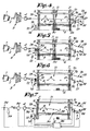
- Fig. 1 shows a weft insertion mechanism of a weaving machine according to the present invention.
- the conventional elements and components to be found in such a weft insertion mechanism are, as is commonly known, a yarn package 1, the weft thread 2 drawn from the yarn package, a weft accumulator mechanism such as e.g. a prewinder 3, insertion devices such as e.g. a main nozzle 4 and relay nozzles 5, the woven cloth 6, the warp threads 7, the cloth fell or fell line 8, the reed 9, the weft detector 10, the shed 11 and a cutting device 12 which operates on the weft thread 2 at the picking side 13 of the shed 11.
- a weft accumulator mechanism such as e.g. a prewinder 3
- insertion devices such as e.g. a main nozzle 4 and relay nozzles 5
- the woven cloth 6 the warp threads 7, the cloth fell or fell line 8
- the reed 9 the weft detector 10
- a thread reversing device 14 which is mounted at the picking side 13 of the shed 11 and which can be presented to the weft thread 2.
- This thread reversing device 14 consists of a winder which has a number of pins or fingers 15, for instance around the circumference of a circle, so that when it is turned the thread is wound up.
- Another important characteristic of the invention consists of a special detection device 17 which is mounted at the receiving side 16 of the shed 11, and which, as is explained in greater detail below, can differentiate between a section of thread coming directly from the main nozzle 4 and a thread section coming from the direction of the fell line 8.
- this detection device 17 consists preferrably of a nozzle (18), for example a suction nozzle in the form of a flattened pipe, with a thread detector 20 on the side 19 nearest the cloth fell 8, while mounted centrally in the nozzle 18 there should preferrably be a blower nozzle 21.
- a nozzle for example a suction nozzle in the form of a flattened pipe, with a thread detector 20 on the side 19 nearest the cloth fell 8, while mounted centrally in the nozzle 18 there should preferrably be a blower nozzle 21.
- Detector 20 serves to detect a thread 2 coming from the cloth fell 8
- detector 22 serves to detect a thread coming from the main nozzle 4.
- the suction nozzle can be dispensed with and only a pipe with a blower nozzle 23 used.
- the detectors 20 and 22 may or may not each be formed by two components mounted diametrically opposite each other (as shown for detector 22), where these two-component detectors can be mounted horizontally and vertically in any plane.
- the first faulty weft section 24 can, as described in Dutch patent application No. 86.02 191 made by the present applicant and as shown in fig. 2, be separated from the cloth fell 8 and removed from the shed in the form of a loop 27 by inserting a new length of weft thread 2 into the shed.
- the thread detector 20 will not detect a thread any more, as shown in fig. 3. At that moment the cutting device 12 can operate so that the weft section 2, present in the shed 11 and extending into the nozzle 18 and beyond, is cut and removed. In this case detector 20 checks whether the weft thread section 24 has in fact been removed. The weaving machine can then be restarted.
- FIG. 4 to 6 show a method for removing the above-mentioned faulty weft section 24 from the shed if for any reason it should be come caught or tangled in the shed 11 at a particular point 30, for instance between the warp threads 7.
- a new weft thread inserted in the form of a loop 27 cannot exert sufficient tractive force to pull the faulty weft section 24 free.
- thread detector 20 still detects a thread, thus indicating that the weft section concerned 24 has not come free.
- the thread reversing device 14 is activated.
- the weft thread 2 is cut, in this case behind the main nozzle 4, and then the extracted, wound-up length of thread 31 is evacuated.
- Fig. 7 shows a variant of the thread reversing device, which in this case consists of a reversing nozzle 32 mounted before the main nozzle 4, by means of which the faulty weft section 24 can be removed.
- the reversing nozzle 32 can also be used in combination with the above-mentioned reversing winder 14, in which case the reversing nozzle 32 ensures that the faulty weft section 24 is partly extracted, so forming a certain reserve 33, after which the reversing winder 14 operates and winds a few turns. Since there is a thread reserve 33, in this case no turns have to taken from the prewinder while the reversing winder 14 is operating, and clip 34 can be closed. After the reversing winder 14 has made a few turns, the weft thread 2 can be cut by the cutting device 12 and the rest of the faulty weft section 24 can be wound up and drawn free.
- the thread reversing device 14 or 32 can be deactivated whenever the tension rises above a set threshold. This offers the advantage that the tractive force exerted on the weft thread is set according to the breaking strength of the thread 2, thus making it unlikely that the faulty weft section 24 will break. If the thread still does not come free at the maximum set tension, a signal can be given so that the weaver can intervene manually.
- control unit 36 interprets the signals from the detectors 20, 22 and 35 and controls the operation of all the above-mentioned mechanisms.
- the information from these detectors can for example be stored in a memory and/or passed on directly to the control unit.
Landscapes
- Engineering & Computer Science (AREA)
- Textile Engineering (AREA)
- Looms (AREA)
Applications Claiming Priority (2)
| Application Number | Priority Date | Filing Date | Title |
|---|---|---|---|
| BE8700945 | 1987-08-26 | ||
| BE8700945A BE1000883A3 (nl) | 1987-08-26 | 1987-08-26 | Werkwijze voor het verwijderen van een foutieve inslagdraad uit de gaap van een weefmachine en weefmachine die deze werkwijze toepast |
Publications (2)
| Publication Number | Publication Date |
|---|---|
| EP0309013A1 true EP0309013A1 (fr) | 1989-03-29 |
| EP0309013B1 EP0309013B1 (fr) | 1991-08-21 |
Family
ID=3882825
Family Applications (1)
| Application Number | Title | Priority Date | Filing Date |
|---|---|---|---|
| EP19880201639 Expired EP0309013B1 (fr) | 1987-08-26 | 1988-07-29 | Procédé pour retirer un fil de trame fautif de la foule sur un métier à tisser et métier à tisser utilisant ce procédé |
Country Status (3)
| Country | Link |
|---|---|
| EP (1) | EP0309013B1 (fr) |
| BE (1) | BE1000883A3 (fr) |
| DE (1) | DE3864364D1 (fr) |
Cited By (14)
| Publication number | Priority date | Publication date | Assignee | Title |
|---|---|---|---|---|
| FR2642769A1 (fr) * | 1989-02-07 | 1990-08-10 | Saurer Diederichs Sa | Dispositif pour la detection de defauts du fil de trame dans une machine a tisser |
| US5005609A (en) * | 1988-05-25 | 1991-04-09 | S.A. Saurer Diederichs | Pneumatic removal of defective weft filament |
| EP0492461A1 (fr) * | 1990-12-28 | 1992-07-01 | TSUDAKOMA Corp. | Méthode pour éloigner un fil de trame cassé |
| BE1004529A3 (fr) * | 1989-08-25 | 1992-12-08 | Toyoda Automatic Loom Works | Appareil de traitement de trame destine a un metier a injection. |
| EP0534541A1 (fr) * | 1991-09-18 | 1993-03-31 | SOMET SOCIETA' MECCANICA TESSILE S.p.A. | Procédé pour retirer automatiquement un fil de trame cassé de la foule sur un métier à tisser à jet d'air et dispositif pneumomécanique utilisé dans ce procédé |
| EP0562230A1 (fr) * | 1992-03-25 | 1993-09-29 | Lindauer Dornier Gesellschaft M.B.H | Procédé et dispositif pour la fabrication d'un tissu, particulièrement un tissu sans noeuds, sur un métier à jet d'air |
| EP0575990A1 (fr) * | 1992-06-26 | 1993-12-29 | Tsudakoma Kogyo Kabushiki Kaisha | Méthode pour éloigner un fil de trame cassé |
| EP0584738A1 (fr) * | 1992-08-21 | 1994-03-02 | Tsudakoma Kogyo Kabushiki Kaisha | Dispositif pour l'extraction d'un fil de trame défectueux sur un métier à tisser |
| DE19521100C1 (de) * | 1995-06-09 | 1996-07-11 | Dornier Gmbh Lindauer | Kontrollierte Absaugung an Webmaschinen |
| DE19521106A1 (de) * | 1995-06-09 | 1996-12-12 | Dornier Gmbh Lindauer | Verfahren zur Schußstoppbehebung |
| KR100266959B1 (ko) * | 1997-03-24 | 2000-09-15 | 데라다 도키오 | 미스사처리방법 |
| EP1508633A1 (fr) | 2003-08-15 | 2005-02-23 | Sultex AG | Métier à tisser à jet |
| DE102016208186A1 (de) | 2016-05-12 | 2017-11-16 | Rwth Aachen | Bildbasierte Webfachüberwachung zur Unterstützung der automatisierten Behebung von Schusseintragsfehlern in Luftdüsenwebmaschinen |
| EP4317558A1 (fr) | 2022-08-04 | 2024-02-07 | ITEMA S.p.A. | Dispositif pour l'élimination automatique de faux fils de trame pour métiers à tisser à jet d'air et procédé associé |
Citations (3)
| Publication number | Priority date | Publication date | Assignee | Title |
|---|---|---|---|---|
| FR2248353A1 (fr) * | 1973-10-20 | 1975-05-16 | Dornier Gmbh Lindauer | |
| FR2537168A1 (fr) * | 1982-12-01 | 1984-06-08 | Rueti Te Strake Bv | Metier a tisser sans navette comprenant un moyen pour retirer, de la foule, des fils defectueux de trame |
| US4664157A (en) * | 1985-01-09 | 1987-05-12 | Tsukakoma Corp. | Incomplete weft removing device for shuttleless loom |
-
1987
- 1987-08-26 BE BE8700945A patent/BE1000883A3/nl not_active IP Right Cessation
-
1988
- 1988-07-29 EP EP19880201639 patent/EP0309013B1/fr not_active Expired
- 1988-07-29 DE DE8888201639T patent/DE3864364D1/de not_active Expired - Lifetime
Patent Citations (3)
| Publication number | Priority date | Publication date | Assignee | Title |
|---|---|---|---|---|
| FR2248353A1 (fr) * | 1973-10-20 | 1975-05-16 | Dornier Gmbh Lindauer | |
| FR2537168A1 (fr) * | 1982-12-01 | 1984-06-08 | Rueti Te Strake Bv | Metier a tisser sans navette comprenant un moyen pour retirer, de la foule, des fils defectueux de trame |
| US4664157A (en) * | 1985-01-09 | 1987-05-12 | Tsukakoma Corp. | Incomplete weft removing device for shuttleless loom |
Cited By (23)
| Publication number | Priority date | Publication date | Assignee | Title |
|---|---|---|---|---|
| US5005609A (en) * | 1988-05-25 | 1991-04-09 | S.A. Saurer Diederichs | Pneumatic removal of defective weft filament |
| FR2642769A1 (fr) * | 1989-02-07 | 1990-08-10 | Saurer Diederichs Sa | Dispositif pour la detection de defauts du fil de trame dans une machine a tisser |
| EP0382662A1 (fr) * | 1989-02-07 | 1990-08-16 | S.A. Saurer Diederichs | Dispositif pour la détection de défauts du fil de trame dans une machine à tisser |
| BE1004529A3 (fr) * | 1989-08-25 | 1992-12-08 | Toyoda Automatic Loom Works | Appareil de traitement de trame destine a un metier a injection. |
| EP0492461A1 (fr) * | 1990-12-28 | 1992-07-01 | TSUDAKOMA Corp. | Méthode pour éloigner un fil de trame cassé |
| EP0534541A1 (fr) * | 1991-09-18 | 1993-03-31 | SOMET SOCIETA' MECCANICA TESSILE S.p.A. | Procédé pour retirer automatiquement un fil de trame cassé de la foule sur un métier à tisser à jet d'air et dispositif pneumomécanique utilisé dans ce procédé |
| EP0562230A1 (fr) * | 1992-03-25 | 1993-09-29 | Lindauer Dornier Gesellschaft M.B.H | Procédé et dispositif pour la fabrication d'un tissu, particulièrement un tissu sans noeuds, sur un métier à jet d'air |
| EP0575990A1 (fr) * | 1992-06-26 | 1993-12-29 | Tsudakoma Kogyo Kabushiki Kaisha | Méthode pour éloigner un fil de trame cassé |
| EP0584738A1 (fr) * | 1992-08-21 | 1994-03-02 | Tsudakoma Kogyo Kabushiki Kaisha | Dispositif pour l'extraction d'un fil de trame défectueux sur un métier à tisser |
| US5345975A (en) * | 1992-08-21 | 1994-09-13 | Tsudakoma Kogyo Kabushiki Kaisha | Multiple weft removing devices for a loom |
| DE19521100C1 (de) * | 1995-06-09 | 1996-07-11 | Dornier Gmbh Lindauer | Kontrollierte Absaugung an Webmaschinen |
| EP0747520A2 (fr) | 1995-06-09 | 1996-12-11 | Lindauer Dornier Gesellschaft M.B.H | Procédé et dispositif pour le tirage pneumatique commandé de fils de trame pour la réparation de fil de trame cassé sur métiers à jet d'air |
| DE19521106A1 (de) * | 1995-06-09 | 1996-12-12 | Dornier Gmbh Lindauer | Verfahren zur Schußstoppbehebung |
| US5642759A (en) * | 1995-06-09 | 1997-07-01 | Lindauer Dornier Gesellschaft Mbh | Method for avoiding weaving a faulty weft thread during repair of weft thread fault |
| EP0747520A3 (fr) * | 1995-06-09 | 1997-09-24 | Dornier Gmbh Lindauer | Procédé et dispositif pour le tirage pneumatique commandé de fils de trame pour la réparation de fil de trame cassé sur métiers à jet d'air |
| EP0747519A3 (fr) * | 1995-06-09 | 1997-09-24 | Dornier Gmbh Lindauer | Procédé pour éviter l'entretissage d'un fil de trame cassé dans un tissu |
| US5746256A (en) * | 1995-06-09 | 1998-05-05 | Lindauer Dornier Gesellschaft Mbh | Method and apparatus for a controlled pneumatic removal of a faulty weft thread in an air jet loom |
| KR100266959B1 (ko) * | 1997-03-24 | 2000-09-15 | 데라다 도키오 | 미스사처리방법 |
| EP1508633A1 (fr) | 2003-08-15 | 2005-02-23 | Sultex AG | Métier à tisser à jet |
| EP1508633B1 (fr) * | 2003-08-15 | 2008-10-29 | Sultex AG | Métier à tisser à jet |
| DE102016208186A1 (de) | 2016-05-12 | 2017-11-16 | Rwth Aachen | Bildbasierte Webfachüberwachung zur Unterstützung der automatisierten Behebung von Schusseintragsfehlern in Luftdüsenwebmaschinen |
| WO2017194730A1 (fr) | 2016-05-12 | 2017-11-16 | Rwth Aachen | Dispositif et procédé de contrôle de foule sur la base d'images |
| EP4317558A1 (fr) | 2022-08-04 | 2024-02-07 | ITEMA S.p.A. | Dispositif pour l'élimination automatique de faux fils de trame pour métiers à tisser à jet d'air et procédé associé |
Also Published As
| Publication number | Publication date |
|---|---|
| BE1000883A3 (nl) | 1989-05-02 |
| DE3864364D1 (de) | 1991-09-26 |
| EP0309013B1 (fr) | 1991-08-21 |
Similar Documents
| Publication | Publication Date | Title |
|---|---|---|
| EP0309013B1 (fr) | Procédé pour retirer un fil de trame fautif de la foule sur un métier à tisser et métier à tisser utilisant ce procédé | |
| EP0236597B1 (fr) | Dispositif pour éloigner un fil de trame cassé à un métier à tisser sans navette | |
| US5544679A (en) | Defective weft yarn insertion prevention | |
| US4924917A (en) | Weft thread break monitor and movement limiting device | |
| EP0292044B1 (fr) | Procédé de tissage et métier à tisser utilisant ce procédé | |
| EP0269140A1 (fr) | Procédé et dispositif pour réparer l'alimentation du fil dans les machines à tisser dans le cas d'une interruption entre la bobine d'alimentation et l'accumulateur de fil de trame | |
| EP0332258A1 (fr) | Procédé pour retirer une pièce détachée de fil de trame fautif de la foule d'un métier à tisser | |
| US5050647A (en) | Damaged weft thread elimination in airjet weaving machines | |
| RU2051229C1 (ru) | Ткацкий станок с зажимными челноками и способ устранения оборванной уточной нити на этом станке | |
| EP0344848B1 (fr) | Procédé d'enfilage de tuyères avec une longueur de fil de trame exacte et métier à tisser utilisant ce procédé | |
| EP1382727A1 (fr) | Dispositif pour éviter un démarrage accidentel d'un métier à tisser | |
| JPH073021B2 (ja) | 無杼織機の不完全緯入れ糸除去装置 | |
| US5345975A (en) | Multiple weft removing devices for a loom | |
| US4805670A (en) | Method and apparatus for detecting clinging warp threads in a weaving machine | |
| JPH01306652A (ja) | ジェットルームに不正確に挿入された緯糸を除去する方法と該方法を実施する装置 | |
| JP2889051B2 (ja) | よこ入れの不良糸除去方法 | |
| JP3122251B2 (ja) | 不良糸除去方法 | |
| EP0853693B1 (fr) | Procede d'extraction automatique de fils de trame defectueux a partir de la foule du metier a tisser a projectile | |
| JP3094643B2 (ja) | ジェットルームにおける緯糸処理方法 | |
| EP0493859A1 (fr) | Dispositif pour retirer les fils de trame défectueux dans un métier à tisser à jet | |
| JPH08311745A (ja) | ジェットルームの給糸装置 | |
| JPH05186937A (ja) | 不良糸除去方法 | |
| JP2526577B2 (ja) | ジエツトル−ムにおける緯糸処理装置 | |
| JP2889765B2 (ja) | 織機の不良緯糸除去装置 | |
| JP2530132B2 (ja) | 無杼織機の不良糸除去装置 |
Legal Events
| Date | Code | Title | Description |
|---|---|---|---|
| PUAI | Public reference made under article 153(3) epc to a published international application that has entered the european phase |
Free format text: ORIGINAL CODE: 0009012 |
|
| AK | Designated contracting states |
Kind code of ref document: A1 Designated state(s): CH DE FR IT LI |
|
| 17P | Request for examination filed |
Effective date: 19890413 |
|
| 17Q | First examination report despatched |
Effective date: 19901026 |
|
| GRAA | (expected) grant |
Free format text: ORIGINAL CODE: 0009210 |
|
| AK | Designated contracting states |
Kind code of ref document: B1 Designated state(s): CH DE FR IT LI |
|
| REF | Corresponds to: |
Ref document number: 3864364 Country of ref document: DE Date of ref document: 19910926 |
|
| ET | Fr: translation filed | ||
| ITF | It: translation for a ep patent filed | ||
| PLBE | No opposition filed within time limit |
Free format text: ORIGINAL CODE: 0009261 |
|
| STAA | Information on the status of an ep patent application or granted ep patent |
Free format text: STATUS: NO OPPOSITION FILED WITHIN TIME LIMIT |
|
| 26N | No opposition filed | ||
| PGFP | Annual fee paid to national office [announced via postgrant information from national office to epo] |
Ref country code: FR Payment date: 20050628 Year of fee payment: 18 |
|
| PGFP | Annual fee paid to national office [announced via postgrant information from national office to epo] |
Ref country code: CH Payment date: 20050706 Year of fee payment: 18 |
|
| PG25 | Lapsed in a contracting state [announced via postgrant information from national office to epo] |
Ref country code: IT Free format text: LAPSE BECAUSE OF NON-PAYMENT OF DUE FEES;WARNING: LAPSES OF ITALIAN PATENTS WITH EFFECTIVE DATE BEFORE 2007 MAY HAVE OCCURRED AT ANY TIME BEFORE 2007. THE CORRECT EFFECTIVE DATE MAY BE DIFFERENT FROM THE ONE RECORDED. Effective date: 20050729 |
|
| PGFP | Annual fee paid to national office [announced via postgrant information from national office to epo] |
Ref country code: DE Payment date: 20050815 Year of fee payment: 18 |
|
| PG25 | Lapsed in a contracting state [announced via postgrant information from national office to epo] |
Ref country code: LI Free format text: LAPSE BECAUSE OF NON-PAYMENT OF DUE FEES Effective date: 20060731 Ref country code: CH Free format text: LAPSE BECAUSE OF NON-PAYMENT OF DUE FEES Effective date: 20060731 |
|
| PG25 | Lapsed in a contracting state [announced via postgrant information from national office to epo] |
Ref country code: DE Free format text: LAPSE BECAUSE OF NON-PAYMENT OF DUE FEES Effective date: 20070201 |
|
| REG | Reference to a national code |
Ref country code: CH Ref legal event code: PL |
|
| REG | Reference to a national code |
Ref country code: FR Ref legal event code: ST Effective date: 20070330 |
|
| PG25 | Lapsed in a contracting state [announced via postgrant information from national office to epo] |
Ref country code: FR Free format text: LAPSE BECAUSE OF NON-PAYMENT OF DUE FEES Effective date: 20060731 |