EP0309165A2 - Procédé pour corriger la sensibilité d'une caméra gamma - Google Patents
Procédé pour corriger la sensibilité d'une caméra gamma Download PDFInfo
- Publication number
- EP0309165A2 EP0309165A2 EP88308597A EP88308597A EP0309165A2 EP 0309165 A2 EP0309165 A2 EP 0309165A2 EP 88308597 A EP88308597 A EP 88308597A EP 88308597 A EP88308597 A EP 88308597A EP 0309165 A2 EP0309165 A2 EP 0309165A2
- Authority
- EP
- European Patent Office
- Prior art keywords
- correction
- data
- collimator
- uniformity
- sensitivity
- Prior art date
- Legal status (The legal status is an assumption and is not a legal conclusion. Google has not performed a legal analysis and makes no representation as to the accuracy of the status listed.)
- Granted
Links
Images




Classifications
-
- G—PHYSICS
- G01—MEASURING; TESTING
- G01T—MEASUREMENT OF NUCLEAR OR X-RADIATION
- G01T1/00—Measuring X-radiation, gamma radiation, corpuscular radiation, or cosmic radiation
- G01T1/16—Measuring radiation intensity
- G01T1/161—Applications in the field of nuclear medicine, e.g. in vivo counting
- G01T1/164—Scintigraphy
- G01T1/1641—Static instruments for imaging the distribution of radioactivity in one or two dimensions using one or several scintillating elements; Radio-isotope cameras
- G01T1/1642—Static instruments for imaging the distribution of radioactivity in one or two dimensions using one or several scintillating elements; Radio-isotope cameras using a scintillation crystal and position sensing photodetector arrays, e.g. ANGER cameras
-
- A—HUMAN NECESSITIES
- A61—MEDICAL OR VETERINARY SCIENCE; HYGIENE
- A61B—DIAGNOSIS; SURGERY; IDENTIFICATION
- A61B6/00—Apparatus or devices for radiation diagnosis; Apparatus or devices for radiation diagnosis combined with radiation therapy equipment
- A61B6/42—Arrangements for detecting radiation specially adapted for radiation diagnosis
- A61B6/4208—Arrangements for detecting radiation specially adapted for radiation diagnosis characterised by using a particular type of detector
- A61B6/4258—Arrangements for detecting radiation specially adapted for radiation diagnosis characterised by using a particular type of detector for detecting non x-ray radiation, e.g. gamma radiation
Definitions
- This invention relates to a gamma camera sensitivity correcting device.
- a gamma camera When such a gamma camera is used, the subject is dosed with a radio-isotope (hereinbelow abbreviated to RI), and the amount of this RI that is selectively accumulated in a specific organ or disease site is detected, and imaged as an accumulation image.
- RI radio-isotope
- Detector 15 detects radiation (gamma rays) from the RI. It consists of a scintillator 17, light guide 18, photoelectron multiplier tubes 19, and pre-amplifiers 20. Gamma rays cannot be refracted and focused by a lens as in an optical camera, so a collimator 16 is arranged ahead of detector 15. Collimator 16 is built around a lead sheet provided with a large number of parallel holes. By this means an image of the same size as the subject is created at the surface of scintillator 17.
- photoelectron multiplier tubes (PMT) 19 are arranged in hexagonally close-packed fashion on the other side of light-guide 18, which is constructed of a transparent substance (lucite or the like).
- a large number (19, 37 or 61) of PMTs 19, of 2-inch or 3-inch diameter, are used, arranged in a hexagonal pattern.
- PMTs 19 When gamma rays are incident on scintillator 17, their energy is absorbed, causing fluorescence at the point of absorption.
- This light is input via light guide 18 to PMTs 19, where it is subjected to a photoelectric conversion, so that output pulses proportional to the incoming light are output from each PMT 19.
- the point of luminescence i.e. the position of gamma ray incidence, can be found from the output pulses of PMTs 19.
- adder 21 multiplies the outputs of the respective PMTs 19 by coefficients (called "weights") that depend on the positional coordintes of the respective PMT and adds them, to obtain signals for the various directions X+, X ⁇ , Y+, and Y ⁇ .
- the resultant signal will be proportional to the total luminescence of the scintillator, i.e. to the energy of the gamma ray.
- This Z signal is amplified by amplifier 22, then input to pulse wave height analyser 25, so that only gamma rays of the required preset energy are selected.
- the X+, X ⁇ , Y+, and Y ⁇ position signals and the Z signal are each amplified and then the signals of the selected gamma rays only are input to a waveform expanding circuit 23, from the output of which signals: are obtained.
- the reason for dividing by Z is to make the magnitude of the image independent of the gamma ray energy.
- These X and Y signals are applied to the deflecting input of a cathode ray oscilloscope (CRT).
- the output of pulse wave height analyser 25 is applied to a spot generating circuit 26, so that each incoming gamma ray is displayed as a luminous point on CRT 27.
- a 2-dimensional image can be obtained by recording and accumulating these luminous points on polaroid film or X-ray film by means of lens. It is also possible to record and accumulate the frequency with which gamma rays arrive in an IC memory corresponding to X and Y to obtain a functional diagnostic image by carrying out data processing on the data stored in this IC.
- Figure 2 shows a case where such a functional diagnostic image is obtained.
- the Z signal is also supplied to correction part 7, where it is corrected by performing the calculation.
- Z′ e(X,Y).Z
- This corrected Z′ is supplied to window circuit 9, constituting the next stage, and, if this input Z′ is a prescribed energy value, causes the pixel value of the corresponding address of image data memory 10 to be incremented by +1.
- the memory content of image data memory 10 is input to main CPU (central processing unit 8) through line 11 and the values of Z, X, and Y are input to main CPU 8 through lines 12 and 13, where calculation and rewriting of the correction coefficients are performed.
- collimator 16 shows differences in the proportion of gamma rays that it lets through, depending on the precision with which it was machined and on the location (X,Y). Consequently, in the case of ECT, there were the problems that ring-shaped artifacts were formed in the reconstructed image due to statistical scatter in the uniformity of the sensitivity of the gamma camera, or that artifacts were produced with lapse of time (however, such artifacts are not produced if the correction data are re-written to match time-wise variation, as mentioned above).
- This correction of uniformity of sensitivity for ECT collection purposes was carried out by creating a correction table (matrix) from the uniformity data of detector 15 (scintillator + light guide + photoelectron multiplier) + electrical system + collimator 16, and implementing a sensitivity correction as (collimator + detector) by multiplying the data in image data memory 10 by these coefficients.
- a correction table matrix
- steps (1) to (3) are necessary:
- step (3) above the data collection required for sensitivity correction of the detector with collimator fitted (step (3) above) usually takes 2 to 3 hours, and it is difficult to perform this data collection frequently, since there are a number of different types of collimator.
- the object of this invention is to provide a gamma camera sensitivity correction device whereby the uniformity correction matrix for sensitivity correction can be obtained rapidly.
- the gamma camera sensitivity correction device consists in a sensitivity correction device for a gamma camera in which radiation from a radioisotope administered to a subject is detected and used to obtain a radioisotope accumulation image of said subject, said correction device comprising: first calculating means for finding the sensitivity data that are characteristic of said collimator; means for freshly collecting uniformity data that are characteristic of the detector itself in the condition where said collimator is removed; means for deriving uniformity data in the condition where the collimator is mounted on said detector, based on the uniformity data from this collection means, that are characteristic of the detector itself, and on the sensitivity data from said first calculating means, that are characteristic of the collimator; and second calculating means for finding the uniformity correction coefficients for correcting the radioisotope accumulation image, based on the uniformity data from this derivation means.
- this sensitivity data that is characteristic of the collimator is stored beforehand in the memory means.
- the correction coefficients to be finally applied are found from the uniformity data that are derived in the condition in which the collimator is mounted on the detector, based on uniformity data that are characteristic of the detector (these being freshly collected with the collimator removed) and on the aforementioned sensitivity data that is characteristic of the collimator.
- the uniformity data that are characteristic of the detector can be collected with the collimator is removed; this makes it possible to do this in a short time, using a small radiation source.
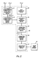
- Figure 3 shows an embodiment of a gamma camera sensitivity correction device according to this invention.
- the device 30 of this embodiment is provided with: collimator characteristic sensitivity calculating means 31, collimator characteristic sensitivity memory means 32, self diagnostic means 33, uniformity data derivation means 34, correction coefficient calculating means 35, correction coefficient memory means 36, and sensitivity correction means 37.
- collimator characteristic sensitivity calculating means 31 The data Ucol(i,j) that are found by this collimator characteristic sensitivity calculating means 31 are written to collimator characteristic sensitivity memory means 32, which is located in a subsequent stage. Thus a table of the collimator's sensitivity characteristic is formed in this memory means 32.
- self diagnostic means 33 finds the difference between the data U(i,j) freshly collected with collimator removed and the previously collected U(i,j) data. Depending on the magnitude of the difference between these two, it discriminates whether compilation of a uniformity correction matrix is appropriate or not. If it decides that it is appropriate, it sends the U(i,j) data to uniformity data derivation means 34.
- This data F′(i,j) derived by uniformity data derivation means 34 is then sent to correction coefficient calculating means 35 that is provided in a subsequent stage.
- this correction coefficient calculating means 34 finds the uniformity correction coefficients for correcting the RI accumulated image. If these uniformity correction coefficients are represented as f(i,j), these f(i,j) are derived by performing the calculation of equation (3) below. where x.y means the total number of pixels in one RI accumulation image frame. Thus the found correction coefficients f(x,y) are written to correction coefficient memory means 36 provided in a subsequent stage, so that a correction table is formed in this correction coefficient memory means 36. This table constitutes the uniformity correction matrix of the detector with collimator mounted.
- Sensitivity correction means 37 performs sensitivity correction as (collimator + detector) using this uniformity correction matrix. This sensitivity correction is performed by multiplying the image data, i.e. the RI accumulated image data, in image data memory 10 by the correction coefficients held in correction coefficient memory means 36. This image data memory 10 corresponds to that indicated by the same reference numeral in Figure 2.
- Collimator characteristic sensitivity calculating means 31, self diagnostic means 33, uniformity data derivation means 34, correction coefficient calculating means 35, and sensitivity correction means 37 are functionally implemented by a CPU (central processing device).
- the sensitivity correction table that is characteristic of collimator 16 is already formed in collimator characteristic sensitivity memory means 32.
- This sensitivity correction table is found by collimator characteristic sensitivity calculating means 31. Specifically as shown in Figure 4, the uniformity data F(i,j) in the condition in which collimator 16 is fitted on detector 15 in the gamma camera are collected (S1), then, the uniformity data U(l,j) in the condition in which this collimator 16 is removed are collected (S2).
- these F(i,j) and U(i,j) are input to collimator characteristic sensitivity calculating means 31, where Ucol(i,j) are found by carrying out the calculation of equation (1) above.
- carrying out steps S1 to S3 may be unnecessary (for example, it is planned that the manufacturer may provide a recording medium containing the sensitivity correction table Ucol(i,j), when such a collimator is shipped).
- the uniformity correction matrix is compiled as follows. (For convenience in the description, steps relating too self-diagnosis are omitted).
- the uniformity data U(i,j) that are characteristic of detector 15 in the condition in which collimator 16 is not fitted to detector 15 in the gamma camera are collected (S4).
- These data U(i,j) are input to uniformity data derivation means 34.
- This uniformity data derivation means 34 derives the uniformity data F′(i,j) in the condition in which collimator 16 is fitted to detector 15 (S5). This derivation is performed by carrying out the calculation of equation (2) given above.
- the calculation of equation (3) given above is performed by this calculating means 35, to find uniformity correction coefficients f(i,j) (S6).
- the thus-found f(i,j) are then written to correction coefficient memory means 36, forming the uniformity correction matrix.
- the collimator's characteristic sensitivity data are treated as known, and only the uniformity data U(i,j) that are characteristic of the detector with collimator 16 removed are collected. Since collimator 16 is not fitted, this collection of uniformity data that are characteristic of the detector can be completed in a short time (about 10 to 20 minutes) using a small radiation source.
- the time required for data collection can therefore be greatly shortened as compared with the time of 2 to 3 hours that was previously necessary for the collection of data to compile the uniformity correction matrix (data collection with collimator mounted).
- This shortening of the data collection time means that compilation of the uniformity matrix (re-writing of the correction table of correction coefficient memory means 36) can be performed frequently.
- compilation of the uniformity matrix of the device of this invention can be carried out before the daily clinical examination, thereby increasing the stability of the gamma camera.
- the uniformity data U(i,j) that are characteristic of detector 15 with collimator 16 not mounted are collected (S7).
- the difference (i.e. the fluctuation) SB is found (S8) between these data U(i,j) and the most recent previously collected data U(i,j).
- a decision is then made (S9) as to whether or not this difference SB is larger than a pre-set value m that was preset to take into account statistical variation. In this decision process, if a decision NO (SB > m does not hold) is made, the U(i,j) are collected (S13), F′(i,j) are derived (S14), and f(i,j) are found (S15).
- steps S13, S14, and S15 correspond to steps S4, S5, and S6 of Figure 5.
- a decision YES SB > m does not hold
- a decision NO SB > m does not hold
- a decision YES (SB > M holds) is made, in view of the possibility that this may be due to a malfunction of the gamma camera, a "correction not possible" message is output, with a request for service by a maintenance engineer (S12). Self-diagnosis of the nature of the abnormality may then be performed.
- steps S8 to S12 are carried out by self-diagnostic means 33.
Landscapes
- Physics & Mathematics (AREA)
- Health & Medical Sciences (AREA)
- Engineering & Computer Science (AREA)
- Biomedical Technology (AREA)
- General Health & Medical Sciences (AREA)
- Medical Informatics (AREA)
- Nuclear Medicine, Radiotherapy & Molecular Imaging (AREA)
- Optics & Photonics (AREA)
- Life Sciences & Earth Sciences (AREA)
- General Physics & Mathematics (AREA)
- High Energy & Nuclear Physics (AREA)
- Molecular Biology (AREA)
- Spectroscopy & Molecular Physics (AREA)
- Nuclear Medicine (AREA)
- Apparatus For Radiation Diagnosis (AREA)
Applications Claiming Priority (2)
| Application Number | Priority Date | Filing Date | Title |
|---|---|---|---|
| JP234416/87 | 1987-09-18 | ||
| JP62234416A JP2653443B2 (ja) | 1987-09-18 | 1987-09-18 | ガンマカメラ感度補正装置 |
Publications (3)
| Publication Number | Publication Date |
|---|---|
| EP0309165A2 true EP0309165A2 (fr) | 1989-03-29 |
| EP0309165A3 EP0309165A3 (en) | 1989-04-05 |
| EP0309165B1 EP0309165B1 (fr) | 1993-02-03 |
Family
ID=16970672
Family Applications (1)
| Application Number | Title | Priority Date | Filing Date |
|---|---|---|---|
| EP88308597A Expired - Lifetime EP0309165B1 (fr) | 1987-09-18 | 1988-09-16 | Procédé pour corriger la sensibilité d'une caméra gamma |
Country Status (4)
| Country | Link |
|---|---|
| US (1) | US4904870A (fr) |
| EP (1) | EP0309165B1 (fr) |
| JP (1) | JP2653443B2 (fr) |
| DE (1) | DE3878117T2 (fr) |
Cited By (2)
| Publication number | Priority date | Publication date | Assignee | Title |
|---|---|---|---|---|
| FR2720166A1 (fr) * | 1994-05-18 | 1995-11-24 | Sopha Medical | Procédé de correction d'uniformité d'une gamma-caméra. |
| WO1998019179A1 (fr) * | 1996-10-27 | 1998-05-07 | Ge Medical Systems Israel, Ltd. | Gamma-camera avec cartes de correction sequentielle |
Families Citing this family (3)
| Publication number | Priority date | Publication date | Assignee | Title |
|---|---|---|---|---|
| JPH0382983A (ja) * | 1989-08-25 | 1991-04-08 | Shimadzu Corp | 放射線カメラ |
| JP2957623B2 (ja) * | 1990-01-31 | 1999-10-06 | 株式会社東芝 | Spect装置用のアーチファクト乃至感度補正装置 |
| JP5091659B2 (ja) * | 2007-12-25 | 2012-12-05 | 株式会社東芝 | X線診断装置 |
Family Cites Families (10)
| Publication number | Priority date | Publication date | Assignee | Title |
|---|---|---|---|---|
| US4060726A (en) * | 1976-10-18 | 1977-11-29 | Beckman Instruments, Inc. | Gamma counter calibration system |
| US4223221A (en) * | 1978-06-19 | 1980-09-16 | Picker Corporation | Scintillation camera uniformity correction |
| US4298944A (en) * | 1979-06-22 | 1981-11-03 | Siemens Gammasonics, Inc. | Distortion correction method and apparatus for scintillation cameras |
| US4429226A (en) * | 1980-05-13 | 1984-01-31 | Elscint, Inc. | Method of and means for improving the resolution of a gamma camera |
| US4424446B1 (en) * | 1980-06-19 | 1994-04-19 | Elscint Ltd | Gamma camera correction system and method for using the same |
| US4588897A (en) * | 1980-06-19 | 1986-05-13 | Elscint, Ltd. | Gamma camera correction system and method for using the same |
| JPS5772087A (en) * | 1980-10-23 | 1982-05-06 | Hitachi Medical Corp | Scinitillation camera |
| JPS60120473A (ja) * | 1983-12-02 | 1985-06-27 | Hitachi Ltd | 衛星画像補正処理方法 |
| US4582995A (en) * | 1984-06-18 | 1986-04-15 | Technicare Corporation | Spatial registration correction for rotational gamma cameras |
| JPH0616097B2 (ja) * | 1985-05-31 | 1994-03-02 | 株式会社島津製作所 | Ect装置の均一性補正法 |
-
1987
- 1987-09-18 JP JP62234416A patent/JP2653443B2/ja not_active Expired - Fee Related
-
1988
- 1988-09-16 DE DE8888308597T patent/DE3878117T2/de not_active Expired - Lifetime
- 1988-09-16 EP EP88308597A patent/EP0309165B1/fr not_active Expired - Lifetime
- 1988-09-16 US US07/245,280 patent/US4904870A/en not_active Expired - Lifetime
Cited By (4)
| Publication number | Priority date | Publication date | Assignee | Title |
|---|---|---|---|---|
| FR2720166A1 (fr) * | 1994-05-18 | 1995-11-24 | Sopha Medical | Procédé de correction d'uniformité d'une gamma-caméra. |
| US5606166A (en) * | 1994-05-18 | 1997-02-25 | Sopha Medical | Method for correcting the uniformity of a gamma camera |
| WO1998019179A1 (fr) * | 1996-10-27 | 1998-05-07 | Ge Medical Systems Israel, Ltd. | Gamma-camera avec cartes de correction sequentielle |
| US6559450B1 (en) | 1996-10-27 | 2003-05-06 | Ge Medical Systems Israel, Ltd. | Gamma camera with two sequential correction maps |
Also Published As
| Publication number | Publication date |
|---|---|
| DE3878117D1 (de) | 1993-03-18 |
| JPS6475986A (en) | 1989-03-22 |
| DE3878117T2 (de) | 1993-05-27 |
| US4904870A (en) | 1990-02-27 |
| EP0309165A3 (en) | 1989-04-05 |
| EP0309165B1 (fr) | 1993-02-03 |
| JP2653443B2 (ja) | 1997-09-17 |
Similar Documents
| Publication | Publication Date | Title |
|---|---|---|
| JP4160275B2 (ja) | エネルギー測定方法及び測定装置 | |
| US7030382B2 (en) | Crystal-based coincidence timing calibration method | |
| US7439515B2 (en) | Pipeline processing of pulse pile-up correction in a nuclear medicine imaging system | |
| EP3977936A1 (fr) | Dispositif d'imagerie radiographique et procédé d'imagerie radiographique | |
| EP0117299B1 (fr) | Dispositif pour formation d'image de rayonnement | |
| US4904870A (en) | Device and method for correcting sensitivity of a gamma camera | |
| JPH04274791A (ja) | ベースポテンシャルを補正した核検出法およびその装置 | |
| US4882680A (en) | Process and device for taking into account locating pulses supplied by a gamma camera | |
| CN1422414A (zh) | 操作辐射检查设备的方法 | |
| US5083024A (en) | Digital x-ray image read apparatus with a correction function | |
| US5606166A (en) | Method for correcting the uniformity of a gamma camera | |
| JPS6042426B2 (ja) | シンチレ−シヨンカメラ | |
| JP2855803B2 (ja) | シンチレーションカメラ | |
| JP2569463B2 (ja) | 光電子増倍管の増幅度安定化装置 | |
| JPH0620235B2 (ja) | 画像信号のノイズ検出方法 | |
| JP2631654B2 (ja) | 画像信号のノイズ検出方法 | |
| JP2631477B2 (ja) | シンチレーションカメラ | |
| JPH02257084A (ja) | γ線の散乱線除去画像収集方法及びガンマカメラ | |
| JPS60122382A (ja) | 放射線結像装置 | |
| JPH0620236B2 (ja) | 画像信号のノイズ検出方法 | |
| JPH0528354B2 (fr) | ||
| JPS6042425B2 (ja) | シンチレ−シヨンカメラ | |
| JPH0528355B2 (fr) | ||
| JPH06105298B2 (ja) | 放射線位置検出装置 | |
| JPH052956B2 (fr) |
Legal Events
| Date | Code | Title | Description |
|---|---|---|---|
| PUAI | Public reference made under article 153(3) epc to a published international application that has entered the european phase |
Free format text: ORIGINAL CODE: 0009012 |
|
| PUAL | Search report despatched |
Free format text: ORIGINAL CODE: 0009013 |
|
| 17P | Request for examination filed |
Effective date: 19881003 |
|
| AK | Designated contracting states |
Kind code of ref document: A2 Designated state(s): DE |
|
| AK | Designated contracting states |
Kind code of ref document: A3 Designated state(s): DE |
|
| 17Q | First examination report despatched |
Effective date: 19901113 |
|
| GRAA | (expected) grant |
Free format text: ORIGINAL CODE: 0009210 |
|
| AK | Designated contracting states |
Kind code of ref document: B1 Designated state(s): DE |
|
| REF | Corresponds to: |
Ref document number: 3878117 Country of ref document: DE Date of ref document: 19930318 |
|
| PLBE | No opposition filed within time limit |
Free format text: ORIGINAL CODE: 0009261 |
|
| STAA | Information on the status of an ep patent application or granted ep patent |
Free format text: STATUS: NO OPPOSITION FILED WITHIN TIME LIMIT |
|
| 26N | No opposition filed | ||
| PGFP | Annual fee paid to national office [announced via postgrant information from national office to epo] |
Ref country code: DE Payment date: 20070913 Year of fee payment: 20 |