EP0309625A1 - Hydraulischer Impuls-Schraubenschlüssel - Google Patents
Hydraulischer Impuls-Schraubenschlüssel Download PDFInfo
- Publication number
- EP0309625A1 EP0309625A1 EP87308642A EP87308642A EP0309625A1 EP 0309625 A1 EP0309625 A1 EP 0309625A1 EP 87308642 A EP87308642 A EP 87308642A EP 87308642 A EP87308642 A EP 87308642A EP 0309625 A1 EP0309625 A1 EP 0309625A1
- Authority
- EP
- European Patent Office
- Prior art keywords
- liner
- anvil
- blades
- oil
- output shaft
- Prior art date
- Legal status (The legal status is an assumption and is not a legal conclusion. Google has not performed a legal analysis and makes no representation as to the accuracy of the status listed.)
- Granted
Links
Images

Classifications
-
- B—PERFORMING OPERATIONS; TRANSPORTING
- B25—HAND TOOLS; PORTABLE POWER-DRIVEN TOOLS; MANIPULATORS
- B25B—TOOLS OR BENCH DEVICES NOT OTHERWISE PROVIDED FOR, FOR FASTENING, CONNECTING, DISENGAGING, OR HOLDING
- B25B21/00—Portable power-driven screw or nut setting or loosening tools; Attachments for drilling apparatus serving the same purpose
- B25B21/02—Portable power-driven screw or nut setting or loosening tools; Attachments for drilling apparatus serving the same purpose with means for imparting impact to screwdriver blade or nut socket
-
- B—PERFORMING OPERATIONS; TRANSPORTING
- B25—HAND TOOLS; PORTABLE POWER-DRIVEN TOOLS; MANIPULATORS
- B25B—TOOLS OR BENCH DEVICES NOT OTHERWISE PROVIDED FOR, FOR FASTENING, CONNECTING, DISENGAGING, OR HOLDING
- B25B23/00—Details of, or accessories for, spanners, wrenches, screwdrivers
- B25B23/14—Arrangement of torque limiters or torque indicators in wrenches or screwdrivers
- B25B23/145—Arrangement of torque limiters or torque indicators in wrenches or screwdrivers specially adapted for fluid operated wrenches or screwdrivers
- B25B23/1453—Arrangement of torque limiters or torque indicators in wrenches or screwdrivers specially adapted for fluid operated wrenches or screwdrivers for impact wrenches or screwdrivers
Definitions
- the present invention relates to a hydraulic pulse wrench provided with a hydraulic pulse generator which works as a substitute for a conventional striking tool such as a mechanical impact mechanism.
- a hydraulic pulse wrench which has a hydraulic pulse generator rotatably mounted in a casing and including a liner and an anvil provided with blades, an output shaft integral with the anvil and protruding from the front end of the casing, and an air motor provided at rear of the liner for driving the liner.
- a turning tool secured to the end of the output shaft is mounted on a nut or the like to tighten or loosen it.
- Such an impact torque is generated owing to a high pressure created in one of a pair of oil chambers formed between the anvil and the liner and partitioned by a blade. Since it is a common practice with the prior art torque wrench to use a single blade and thus to shape the anvil and the liner asymmetrically in cross-section, vibrations are inevitably generated.
- the anvil rotates, keeping pace with the liner with the oil interposed therebetween. But, as the nut is tightened harder and offers more resistance, the anvil begins to fall behind the liner in the speed of rotation, until the sealing ridges on the anvil get into sealing contact with the corresponding sealing ridges on the liner and simultaneouly the top ends of the blades sealingly contact the respective sealing ridges on the liner to increase the oil pressure in the high-pressure chambers and produce an impact.
- the anvil of the present invention is provided with two blades to give one impact for each rotation, the anvil and liner do not have to be formed asymmetrically. This minimizes the generation of vibrations.
- the blades mounted in the anvil have their outer ends tapered or beveled in different directions so that the line connecting the tips of the blades will be in an offset position with respect to the center of rotation of the anvil.
- the anvil can take a perfect laterally symmetrical shape.
- the two blades have the same shape in common and have only to be mounted oppositely to each other when assembling, they are easy to manufacture as well as to assemble.
- the anvil is formed on its outer periphery with an opposed pair of axial sealing ridges in a direction perpendicular to the blade mounting portions.
- the liner is formed on its inner periphery with the axial sealing ridges in the direction of breadth of the inner periphery adapted to sealingly contact the sealing ridges on the anvil and with the axial sealing ridge in the direction of its length at one side adapted to sealingly contact the tip of the blade whether in the normal or reverse turn position and at the other side with the two axial sealing ridges each adapted to sealingly contact the tip of the blade when in the normal turn position and in the reverse turn position, respectively.
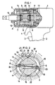
- numeral 1 in Fig. 1 designates a body of the pulse wrench embodying the present invention.
- a conventional air motor is mounted in the body.
- a handle 2 At the bottom of the body 1 is formed a handle 2 in which are mounted a valve for switching on and off the air motor and a valve for reversing the direction of rotation of the air motor.
- These valves are actuated by an ON/OFF lever 3 and a lever 4 for reversing the direction of rotation which are provided in front of the handle 2.
- This power transmission device comprises an anvil 6, a liner 7 mounted on the anvil 6 and two blades 8 and 9 loosely mounted in a longitudinal slit cut through the anvil 6.
- the liner 7 has an elliptic inner periphery arranged eccentrically with respect to the center of rotation of the anvil 6.
- the blades 8 and 9 are biased by springs 14 away from each other so as to be pressed against the inner surface of the liner 7.
- the liner 7 is provided at its front end with a front wall 10 and at its rear end with a rear wall 11. On the front end of the anvil 6 is provided an output shaft 12 protruding through the front wall 10. On the back of the rear wall 11 is integrally provided a shaft 13 which is connected to the output shaft of the air motor.
- the liner 7 is rotatable with respect to the anvil 6 and is formed on its inner periphery with an opposed pair of axial sealing ridges 15 and 16 in the direction of minor axis of the ellipse and with an axial sealing ridge 17 at one side in the direction of its major axis and two axial sealing ridges 18 and 19 at the other side.
- the anvil 6 has in turn an opposed pair of axial sealing ridges 21 and 22 on its outer periphery adapted to sealingly contact the sealing ridges 15 and 16 on the liner, respectively.
- the blades 8 and 9 have their outer ends 23, 24 tapered or beveled. Since they are beveled in different or asymmetrical directions, the line connecting the ends 23 and 24 is offset with respect to the center of rotation of the anvil 6.
- a relief valve 25 provided in a relief duct serves to adjust the flow rate through the duct and thus to adjust the impact strength.
- An automatic oil supply unit B comprises an axial oil storage chamber 30, a pressure valve 31 slidably mounted in the chamber and a spring 32 for biasing the valve 31 to pressurize the chamber.
- the oil storage chamber 30 is formed with a female thread in its rear periphery into which is inserted a screw plug 33.
- the oil storage chamber 30 has its front portion in communication with the low pressure chamber b through a narrow hole 34.
- the valve 31, the spring 32 and a collar 35 are inserted one after the other into the chamber 30, leaving enough space between the valve 31 and the collar 35 to allow the valve 31 to move back.
- the screw plug 33 is put into threaded engagement with the female thread to seal up the rear end of the chamber 30.
- "O" rings are fitted in annular grooves formed in the outer periphery of the valve 31 and in the front outer periphery of the screw plug 33 to maintain the airtightness and liquid-tightness in the chamber 30.
- a turning tool fixed to the end of the output shaft 12 is mounted on a nut to be tightened and the lever 3 is pressed with the lever 4 set in a normal turn position.
- the air motor will start to turn the liner 7 of the hydraulic pulse generator A clockwise in the direction of arrows in Figs. 2, 3 and 4.
- the rotataion of the liner 7 is smoothly transmitted through oil in high-pressure chambers a to the blades 8 and the anvil 6 to rotate the output shaft 12 and thus the nut at a high speed.
- Part of the oil in the high-pressure chamber a flows to the low-pressure chamber b through a passageway 26 with its flow rate throttled on its way by the relief valve 25 so as to control the increase in the pressure difference between the chambers a and b below a predetermined value, thus keeping the impact torque which acts on the blades 8 within a uniform level.
- the oil in the chambers a and b partially leaks to reduce its volume in the chambers.
- the oil in the storage chamber 30 is normally pressurized by the pressure valve 31 biased by the spring 32, part of the oil in the chamber 30 will flow into the chambers a and b through the narrow hole 34 whenever there is a reduction in the volume of oil in the chambers a and b to make up for such a reduction.
- a high pressure gas is sealed in between the valve 31 and the screw plug 33 to pressurize the valve 31.
- This arrangement performs substantially the same function as that shown in Fig. 5.
- the valve 31 of the automatic oil feeding assembly B can move backwardly to increase the volume of the storage chamber 30 to act as an accumulator.
- the storage chamber 30 is small in volume for an accumulator, it is preferable to provide an accumulator besides the storage chamber 30.
Landscapes
- Engineering & Computer Science (AREA)
- Mechanical Engineering (AREA)
- Details Of Spanners, Wrenches, And Screw Drivers And Accessories (AREA)
- Forging (AREA)
Priority Applications (3)
| Application Number | Priority Date | Filing Date | Title |
|---|---|---|---|
| US07/101,963 US4838133A (en) | 1987-09-29 | 1987-09-28 | Hydraulic pulse wrench |
| DE8787308642T DE3779642T2 (de) | 1987-09-29 | 1987-09-29 | Hydraulischer impuls-schraubenschluessel. |
| EP87308642A EP0309625B1 (de) | 1987-09-29 | 1987-09-29 | Hydraulischer Impuls-Schraubenschlüssel |
Applications Claiming Priority (1)
| Application Number | Priority Date | Filing Date | Title |
|---|---|---|---|
| EP87308642A EP0309625B1 (de) | 1987-09-29 | 1987-09-29 | Hydraulischer Impuls-Schraubenschlüssel |
Publications (2)
| Publication Number | Publication Date |
|---|---|
| EP0309625A1 true EP0309625A1 (de) | 1989-04-05 |
| EP0309625B1 EP0309625B1 (de) | 1992-06-03 |
Family
ID=8198053
Family Applications (1)
| Application Number | Title | Priority Date | Filing Date |
|---|---|---|---|
| EP87308642A Expired EP0309625B1 (de) | 1987-09-29 | 1987-09-29 | Hydraulischer Impuls-Schraubenschlüssel |
Country Status (3)
| Country | Link |
|---|---|
| US (1) | US4838133A (de) |
| EP (1) | EP0309625B1 (de) |
| DE (1) | DE3779642T2 (de) |
Cited By (2)
| Publication number | Priority date | Publication date | Assignee | Title |
|---|---|---|---|---|
| EP1920887A1 (de) * | 2006-11-13 | 2008-05-14 | Cooper Power Tools GmbH & Co. | Werkzeug mit einem Hydraulikschlagwerk |
| CN111546277A (zh) * | 2020-05-13 | 2020-08-18 | 泰田集团有限公司 | 一种气动螺丝刀及冲击机构 |
Families Citing this family (18)
| Publication number | Priority date | Publication date | Assignee | Title |
|---|---|---|---|---|
| US5172772A (en) * | 1991-03-11 | 1992-12-22 | Cooper Industries, Inc. | Hydro-impulse screw tool |
| SE504620C2 (sv) * | 1995-04-26 | 1997-03-17 | Atlas Copco Tools Ab | Pneumatiskt momentimpulsverktyg |
| SE509915C2 (sv) * | 1997-06-09 | 1999-03-22 | Atlas Copco Tools Ab | Hydraulisk momentimpulsgeneratoror |
| US5954141A (en) * | 1997-09-22 | 1999-09-21 | Li; Fen-Lien | Air driven motor for a tool |
| US6082986A (en) | 1998-08-19 | 2000-07-04 | Cooper Technologies | Reversible double-throw air motor |
| US6241500B1 (en) | 2000-03-23 | 2001-06-05 | Cooper Brands, Inc. | Double-throw air motor with reverse feature |
| US6708778B2 (en) * | 2001-01-12 | 2004-03-23 | Makita Corporation | Hydraulic unit with increased torque |
| US6487940B2 (en) | 2001-01-23 | 2002-12-03 | Associated Toolmakers Incorporated | Nut driver |
| EP2036679B1 (de) * | 2007-09-11 | 2012-07-11 | Uryu Seisaku Ltd. | Vorrichtung zur Einstellung des Schlagmoments eines hydraulischen Drehmomentschlüssels |
| JP5547004B2 (ja) * | 2010-09-07 | 2014-07-09 | 瓜生製作株式会社 | 油圧式トルクレンチの打撃トルク調節装置 |
| JP6102191B2 (ja) * | 2012-11-07 | 2017-03-29 | マックス株式会社 | オイルパルス工具の圧力緩和機構 |
| US9878435B2 (en) | 2013-06-12 | 2018-01-30 | Makita Corporation | Power rotary tool and impact power tool |
| TW201406501A (zh) * | 2013-10-31 | 2014-02-16 | Quan-Zheng He | 氣動工具的衝擊組 |
| TWM562747U (zh) | 2016-08-25 | 2018-07-01 | 米沃奇電子工具公司 | 衝擊工具 |
| JP6762572B2 (ja) * | 2017-08-31 | 2020-09-30 | 瓜生製作株式会社 | 油圧式トルクレンチの打撃トルク発生装置 |
| JP6816866B2 (ja) * | 2018-10-03 | 2021-01-20 | 瓜生製作株式会社 | 油圧式トルクレンチの打撃トルク調節装置 |
| EP4096870B1 (de) * | 2020-01-29 | 2023-11-29 | Atlas Copco Industrial Technique AB | Elektrowerkzeug zum durchführen von festziehvorgängen, wobei das drehmoment in impulsen abgegeben wird |
| US20260166690A1 (en) * | 2024-12-17 | 2026-06-18 | Techtronic Cordless Gp | Rotary impulse tool |
Citations (8)
| Publication number | Priority date | Publication date | Assignee | Title |
|---|---|---|---|---|
| US3116617A (en) * | 1961-12-12 | 1964-01-07 | Ingersoll Rand Co | Fluid impulse torque tool |
| US3196636A (en) * | 1963-05-15 | 1965-07-27 | Ingersoll Rand Co | Sealing device for power tool |
| DE1503100A1 (de) * | 1963-11-22 | 1969-10-16 | Thor Power Tool Co | Impulswerkzeug |
| EP0105038A1 (de) * | 1982-09-24 | 1984-04-04 | Atlas Copco Aktiebolag | Hydraulisches Drehschlagwerkzeug |
| GB2136719A (en) * | 1983-03-04 | 1984-09-26 | Uryu Seisaku Ltd | Power driven wrench having hydraulic impulse torque generator |
| DE3347016A1 (de) * | 1983-12-24 | 1985-07-18 | Bijon 7433 Dettingen Sarkar | Impulsschrauber |
| EP0243334A1 (de) * | 1986-04-22 | 1987-10-28 | Atlas Copco Aktiebolag | Hydraulischer Drehmomentimpuls-Erzeuger mit Bypass-Vorrichtung |
| EP0254699B1 (de) * | 1986-07-24 | 1990-02-28 | Atlas Copco Aktiebolag | Hydraulischer Drehmoment-Impuls-Erzeuger |
Family Cites Families (1)
| Publication number | Priority date | Publication date | Assignee | Title |
|---|---|---|---|---|
| US4418764A (en) * | 1981-07-14 | 1983-12-06 | Giken Kogyo Kabushiki Kaisha | Fluid impulse torque tool |
-
1987
- 1987-09-28 US US07/101,963 patent/US4838133A/en not_active Expired - Fee Related
- 1987-09-29 DE DE8787308642T patent/DE3779642T2/de not_active Expired - Fee Related
- 1987-09-29 EP EP87308642A patent/EP0309625B1/de not_active Expired
Patent Citations (8)
| Publication number | Priority date | Publication date | Assignee | Title |
|---|---|---|---|---|
| US3116617A (en) * | 1961-12-12 | 1964-01-07 | Ingersoll Rand Co | Fluid impulse torque tool |
| US3196636A (en) * | 1963-05-15 | 1965-07-27 | Ingersoll Rand Co | Sealing device for power tool |
| DE1503100A1 (de) * | 1963-11-22 | 1969-10-16 | Thor Power Tool Co | Impulswerkzeug |
| EP0105038A1 (de) * | 1982-09-24 | 1984-04-04 | Atlas Copco Aktiebolag | Hydraulisches Drehschlagwerkzeug |
| GB2136719A (en) * | 1983-03-04 | 1984-09-26 | Uryu Seisaku Ltd | Power driven wrench having hydraulic impulse torque generator |
| DE3347016A1 (de) * | 1983-12-24 | 1985-07-18 | Bijon 7433 Dettingen Sarkar | Impulsschrauber |
| EP0243334A1 (de) * | 1986-04-22 | 1987-10-28 | Atlas Copco Aktiebolag | Hydraulischer Drehmomentimpuls-Erzeuger mit Bypass-Vorrichtung |
| EP0254699B1 (de) * | 1986-07-24 | 1990-02-28 | Atlas Copco Aktiebolag | Hydraulischer Drehmoment-Impuls-Erzeuger |
Cited By (3)
| Publication number | Priority date | Publication date | Assignee | Title |
|---|---|---|---|---|
| EP1920887A1 (de) * | 2006-11-13 | 2008-05-14 | Cooper Power Tools GmbH & Co. | Werkzeug mit einem Hydraulikschlagwerk |
| US7647986B2 (en) | 2006-11-13 | 2010-01-19 | Cooper Power Tools Gmbh & Co. | Tool |
| CN111546277A (zh) * | 2020-05-13 | 2020-08-18 | 泰田集团有限公司 | 一种气动螺丝刀及冲击机构 |
Also Published As
| Publication number | Publication date |
|---|---|
| DE3779642D1 (de) | 1992-07-09 |
| DE3779642T2 (de) | 1993-01-21 |
| US4838133A (en) | 1989-06-13 |
| EP0309625B1 (de) | 1992-06-03 |
Similar Documents
| Publication | Publication Date | Title |
|---|---|---|
| US4838133A (en) | Hydraulic pulse wrench | |
| US4553948A (en) | Oil pressure type pneumatic torque wrench | |
| EP2425933B1 (de) | Vorrichtung zur Einstellung des Schlagmoments eines hydraulischen Drehmomentschlüssels | |
| EP1048414A1 (de) | Anzieh-steuervorrichtung für drehschlag-schrauber | |
| US5544710A (en) | Pulse tool | |
| JP4217297B2 (ja) | 流体圧トルク衝撃発生装置 | |
| EP1454714B1 (de) | Rotierendes Werkzeug | |
| US4683961A (en) | Hydraulic torque impulse motor | |
| US4735595A (en) | Hydraulic torque impulse tool | |
| EP0398655B1 (de) | Drucküberwachungsmittel für Drehmoment-Schraubenschlüssel | |
| EP1454715B1 (de) | Antrieb-System mit Trägheitsventil und Verfahren zu dessen Anwendung | |
| EP0521898A1 (de) | Impulskupplung mit doppelkolben mit einstellbarem druck | |
| EP0353106B1 (de) | Hydraulischer Drehimpuls-Generator für Schraubenschlüssel | |
| KR20080042147A (ko) | 전동식 충격 조임 공구 | |
| EP3632621B1 (de) | Vorrichtung zur einstellung des schlagdrehmoments eines hydraulischen drehmomentschlüssels | |
| US3214941A (en) | Impulse tool | |
| US4766787A (en) | Two-blade type impulse wrench | |
| EP0721823B1 (de) | Hydraulischer Drehschlagmechanismus | |
| EP4021683B1 (de) | Elektrowerkzeug zur erzeugung eines unmittelbaren drehmoments | |
| JP4383485B2 (ja) | 油圧式トルクレンチの打撃トルク調節装置 | |
| US3717011A (en) | Impulse unit | |
| KR900009321Y1 (ko) | 유압식 펄스렌치 | |
| JPS62193780A (ja) | 油圧レンチのドライビングブレ−ド | |
| JPH0337898Y2 (de) | ||
| JP2967050B2 (ja) | 油圧式トルクレンチの打撃トルク調節装置 |
Legal Events
| Date | Code | Title | Description |
|---|---|---|---|
| PUAI | Public reference made under article 153(3) epc to a published international application that has entered the european phase |
Free format text: ORIGINAL CODE: 0009012 |
|
| AK | Designated contracting states |
Kind code of ref document: A1 Designated state(s): DE FR GB IT SE |
|
| 17P | Request for examination filed |
Effective date: 19890916 |
|
| 17Q | First examination report despatched |
Effective date: 19910425 |
|
| GRAA | (expected) grant |
Free format text: ORIGINAL CODE: 0009210 |
|
| AK | Designated contracting states |
Kind code of ref document: B1 Designated state(s): DE FR GB IT SE |
|
| REF | Corresponds to: |
Ref document number: 3779642 Country of ref document: DE Date of ref document: 19920709 |
|
| ET | Fr: translation filed | ||
| ITF | It: translation for a ep patent filed | ||
| PLBE | No opposition filed within time limit |
Free format text: ORIGINAL CODE: 0009261 |
|
| STAA | Information on the status of an ep patent application or granted ep patent |
Free format text: STATUS: NO OPPOSITION FILED WITHIN TIME LIMIT |
|
| 26N | No opposition filed | ||
| EAL | Se: european patent in force in sweden |
Ref document number: 87308642.5 |
|
| PGFP | Annual fee paid to national office [announced via postgrant information from national office to epo] |
Ref country code: SE Payment date: 19970901 Year of fee payment: 11 |
|
| PGFP | Annual fee paid to national office [announced via postgrant information from national office to epo] |
Ref country code: FR Payment date: 19970905 Year of fee payment: 11 |
|
| PGFP | Annual fee paid to national office [announced via postgrant information from national office to epo] |
Ref country code: GB Payment date: 19970915 Year of fee payment: 11 |
|
| PG25 | Lapsed in a contracting state [announced via postgrant information from national office to epo] |
Ref country code: GB Free format text: LAPSE BECAUSE OF NON-PAYMENT OF DUE FEES Effective date: 19980929 |
|
| PG25 | Lapsed in a contracting state [announced via postgrant information from national office to epo] |
Ref country code: SE Free format text: LAPSE BECAUSE OF NON-PAYMENT OF DUE FEES Effective date: 19980930 |
|
| PGFP | Annual fee paid to national office [announced via postgrant information from national office to epo] |
Ref country code: DE Payment date: 19981123 Year of fee payment: 12 |
|
| GBPC | Gb: european patent ceased through non-payment of renewal fee |
Effective date: 19980929 |
|
| EUG | Se: european patent has lapsed |
Ref document number: 87308642.5 |
|
| PG25 | Lapsed in a contracting state [announced via postgrant information from national office to epo] |
Ref country code: FR Free format text: LAPSE BECAUSE OF NON-PAYMENT OF DUE FEES Effective date: 19990531 |
|
| REG | Reference to a national code |
Ref country code: FR Ref legal event code: ST |
|
| PG25 | Lapsed in a contracting state [announced via postgrant information from national office to epo] |
Ref country code: DE Free format text: LAPSE BECAUSE OF NON-PAYMENT OF DUE FEES Effective date: 20000701 |
|
| PG25 | Lapsed in a contracting state [announced via postgrant information from national office to epo] |
Ref country code: IT Free format text: LAPSE BECAUSE OF NON-PAYMENT OF DUE FEES Effective date: 20050929 |