EP0309715A2 - Autobus guidé sur piste - Google Patents
Autobus guidé sur piste Download PDFInfo
- Publication number
- EP0309715A2 EP0309715A2 EP88113344A EP88113344A EP0309715A2 EP 0309715 A2 EP0309715 A2 EP 0309715A2 EP 88113344 A EP88113344 A EP 88113344A EP 88113344 A EP88113344 A EP 88113344A EP 0309715 A2 EP0309715 A2 EP 0309715A2
- Authority
- EP
- European Patent Office
- Prior art keywords
- vehicle
- axle
- transverse
- trailing
- vehicle axle
- Prior art date
- Legal status (The legal status is an assumption and is not a legal conclusion. Google has not performed a legal analysis and makes no representation as to the accuracy of the status listed.)
- Granted
Links
Images



Classifications
-
- B—PERFORMING OPERATIONS; TRANSPORTING
- B60—VEHICLES IN GENERAL
- B60G—VEHICLE SUSPENSION ARRANGEMENTS
- B60G7/00—Pivoted suspension arms; Accessories thereof
- B60G7/001—Suspension arms, e.g. constructional features
- B60G7/003—Suspension arms, e.g. constructional features of adjustable length
-
- B—PERFORMING OPERATIONS; TRANSPORTING
- B60—VEHICLES IN GENERAL
- B60G—VEHICLE SUSPENSION ARRANGEMENTS
- B60G7/00—Pivoted suspension arms; Accessories thereof
- B60G7/001—Suspension arms, e.g. constructional features
-
- B—PERFORMING OPERATIONS; TRANSPORTING
- B62—LAND VEHICLES FOR TRAVELLING OTHERWISE THAN ON RAILS
- B62D—MOTOR VEHICLES; TRAILERS
- B62D1/00—Steering controls, i.e. means for initiating a change of direction of the vehicle
- B62D1/24—Steering controls, i.e. means for initiating a change of direction of the vehicle not vehicle-mounted
- B62D1/26—Steering controls, i.e. means for initiating a change of direction of the vehicle not vehicle-mounted mechanical, e.g. by a non-load-bearing guide
- B62D1/265—Steering controls, i.e. means for initiating a change of direction of the vehicle not vehicle-mounted mechanical, e.g. by a non-load-bearing guide especially adapted for guiding road vehicles carrying loads or passengers, e.g. in urban networks for public transportation
-
- B—PERFORMING OPERATIONS; TRANSPORTING
- B60—VEHICLES IN GENERAL
- B60G—VEHICLE SUSPENSION ARRANGEMENTS
- B60G2200/00—Indexing codes relating to suspension types
- B60G2200/30—Rigid axle suspensions
- B60G2200/314—Rigid axle suspensions with longitudinally arranged arms articulated on the axle
- B60G2200/315—Rigid axle suspensions with longitudinally arranged arms articulated on the axle at least one of the arms having an A or V shape
-
- B—PERFORMING OPERATIONS; TRANSPORTING
- B60—VEHICLES IN GENERAL
- B60G—VEHICLE SUSPENSION ARRANGEMENTS
- B60G2200/00—Indexing codes relating to suspension types
- B60G2200/40—Indexing codes relating to the wheels in the suspensions
- B60G2200/44—Indexing codes relating to the wheels in the suspensions steerable
-
- B—PERFORMING OPERATIONS; TRANSPORTING
- B60—VEHICLES IN GENERAL
- B60G—VEHICLE SUSPENSION ARRANGEMENTS
- B60G2202/00—Indexing codes relating to the type of spring, damper or actuator
- B60G2202/10—Type of spring
- B60G2202/15—Fluid spring
- B60G2202/152—Pneumatic spring
- B60G2202/1524—Pneumatic spring with two air springs per wheel, arranged before and after the wheel axis
-
- B—PERFORMING OPERATIONS; TRANSPORTING
- B60—VEHICLES IN GENERAL
- B60G—VEHICLE SUSPENSION ARRANGEMENTS
- B60G2204/00—Indexing codes related to suspensions per se or to auxiliary parts
- B60G2204/40—Auxiliary suspension parts; Adjustment of suspensions
- B60G2204/41—Elastic mounts, e.g. bushings
-
- B—PERFORMING OPERATIONS; TRANSPORTING
- B60—VEHICLES IN GENERAL
- B60G—VEHICLE SUSPENSION ARRANGEMENTS
- B60G2204/00—Indexing codes related to suspensions per se or to auxiliary parts
- B60G2204/40—Auxiliary suspension parts; Adjustment of suspensions
- B60G2204/416—Ball or spherical joints
-
- B—PERFORMING OPERATIONS; TRANSPORTING
- B60—VEHICLES IN GENERAL
- B60G—VEHICLE SUSPENSION ARRANGEMENTS
- B60G2206/00—Indexing codes related to the manufacturing of suspensions: constructional features, the materials used, procedures or tools
- B60G2206/01—Constructional features of suspension elements, e.g. arms, dampers, springs
- B60G2206/10—Constructional features of arms
- B60G2206/11—Constructional features of arms the arm being a radius or track or torque or steering rod or stabiliser end link
- B60G2206/111—Constructional features of arms the arm being a radius or track or torque or steering rod or stabiliser end link of adjustable length
- B60G2206/1116—Actively adjustable during driving
-
- B—PERFORMING OPERATIONS; TRANSPORTING
- B60—VEHICLES IN GENERAL
- B60G—VEHICLE SUSPENSION ARRANGEMENTS
- B60G2206/00—Indexing codes related to the manufacturing of suspensions: constructional features, the materials used, procedures or tools
- B60G2206/01—Constructional features of suspension elements, e.g. arms, dampers, springs
- B60G2206/10—Constructional features of arms
- B60G2206/121—Constructional features of arms the arm having an H or X-shape
-
- B—PERFORMING OPERATIONS; TRANSPORTING
- B60—VEHICLES IN GENERAL
- B60G—VEHICLE SUSPENSION ARRANGEMENTS
- B60G2206/00—Indexing codes related to the manufacturing of suspensions: constructional features, the materials used, procedures or tools
- B60G2206/01—Constructional features of suspension elements, e.g. arms, dampers, springs
- B60G2206/10—Constructional features of arms
- B60G2206/124—Constructional features of arms the arm having triangular or Y-shape, e.g. wishbone
-
- B—PERFORMING OPERATIONS; TRANSPORTING
- B60—VEHICLES IN GENERAL
- B60G—VEHICLE SUSPENSION ARRANGEMENTS
- B60G2300/00—Indexing codes relating to the type of vehicle
- B60G2300/10—Railway vehicles
- B60G2300/102—Railway vehicles having track following mechanismn for lateral stability
-
- B—PERFORMING OPERATIONS; TRANSPORTING
- B60—VEHICLES IN GENERAL
- B60G—VEHICLE SUSPENSION ARRANGEMENTS
- B60G2300/00—Indexing codes relating to the type of vehicle
- B60G2300/14—Buses
Definitions
- a disadvantage of this type of tracking of the vehicle axle within the track-defining special route is the expensive, complex and heavy construction of the following vehicle axle and its suspension, which entails various operational disadvantages.
- the swiveling vehicle axle must be provided with an elaborate transverse position lock at the transition to non-marking, hand-guided operation, which cancels the swiveling ability. This makes the axle construction even more expensive and complicated.
- the tire on the inside of the curve rubs against the side or the inside of the thrust roller presses against the transverse guide bar.
- the chafing of the tire flanks on the transverse guide web can be avoided by installing pushing rollers, but these are also not unproblematic, since they often cannot be accommodated for reasons of space and, if they are only small, they are only slight or only are resilient for a short time. If the higher loads last longer, the jockey rollers wear out relatively quickly, especially if they are used in climatically hot environments and can heat up to an unacceptably high degree due to heat absorption from the transverse guide bars, which are strongly heated by sunlight, and due to self-heating due to flexing in the tire lining of the jockey roller.
- the object of the invention is to provide a trackable omnibus that is simple in construction in the area of the trailing vehicle axis and that can also travel without contact within a relatively wide speed range around the design speed of a curve without contact with the trailing vehicle axis through the special route.
- the invention is based on the generic bus and on the basis of the invention proposes the characterizing features of claim 1.
- it is an omnibus with a trailing vehicle axle conventionally connected to the vehicle body, in which the elements of the axle suspension that are otherwise always present are merely modified and / or installed.
- additional design effort is required, it is only very small and hardly takes up any more space or weight.
- the improved tracking of the trailing vehicle axis over a larger speed range around the design speed of a curve is possible in that a higher slip angle between the wheel plane and the direction of travel can be set automatically and depending on the lateral force.
- This pivoting angle given by the pivotability of the trailing vehicle axle, is added to the slip angle that is already automatically set anyway.
- FIG. 1 shows the track-guidable bus 36 on a track-giving special route 1, in which track-determining transverse guide webs 3 are attached on both sides of the road surface 2.
- the clear width between these two opposite transverse guide webs - dimension B - is a total of about 10 cm larger than the total width b of the bus 36.
- the bus shown is one that can optionally be tracked on the special route shown as can also be used without a trace on normal roads using manual steering.
- the front vehicle axle 4 can be steered manually; each of the front vehicle wheels 5 is assigned in advance a transverse guide roller 10 held in the direction of travel 9; the over-all distance of the opposite transverse guide rollers 10 is slightly larger than the clear width B between the opposite transverse guide webs 3, so that the transverse guide rollers 10 rest against the respective transverse guide webs 3 with slight prestress.
- the transverse guide rollers 10 are assigned to the respective vehicle wheels 5 relatively immovably via a support arm 11; thus they make the turning movement of the steerable vehicle wheels 5; conversely, the direction of travel through the transverse guide webs or the transverse guide rollers is impressed on the foldable vehicle wheels 5 during track-guided operation.
- the transverse guide rollers 10 are loaded only by steering forces, but not by transverse forces caused by centrifugal forces or cross winds.
- the steerable vehicle wheels 5 can adjust obliquely to the direction of travel, ie obliquely to the track-determining transverse guide webs 3, so that a transverse force can build up between the tire's contact surface and the road surface 2.
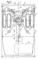
- the axle body 15 of this trailing vehicle axle 6 can be pivoted about a vertical axis 8 which, according to the invention, lies in the direction of travel 9 behind the trailing vehicle axle 6.
- the omnibus 36 is only shown as a single-cell bus with a total of two vehicle axles, so that the trailing vehicle axle 6 is the rear axle; it is driven by a motor 16 arranged in the rear area via an articulated shaft 17 and a differential gear 18.
- the following description applies not only to the rear axle of a single-cell bus, but also to each of the trailing vehicle axles of multi-cell articulated buses.
- the trailing vehicle axle of the front end is not driven in articulated buses; only the trailing vehicle axle of the back-up car is driven.
- a further pair of handlebar rods 24 engage, which are arranged triangularly in the plan and symmetrically to the vehicle center line 25.
- this task could also be performed by a single centrally arranged trailing arm in the area of the upper side of the differential gear 18 and by a single wishbone.
- the joints of the lower trailing arms 20 and the upper steering rods 24 have approximately the same distance in the longitudinal direction of the vehicle, so that the trailing arms 20 and the steering rods 24 together with the axle body 15 are in a side view Form joint parallelogram; as a result, the trailing vehicle axle 6 is guided essentially parallel when deflecting, i. H. there are no torsional vibrations superimposed here due to deflection. The latter would be detrimental to the PTO shaft 17 and also during braking.
- the trailing, unsteerable vehicle axle 6 is one in The vertical axis 8 lying behind the axis 6 can be pivoted.
- the vehicle axle 6 itself is completely left to itself with regard to pivoting, so it does not have any separate guidance means that would be in an operative connection with the route-side guidance means, for example in a touching or contactless manner.
- the trailing vehicle axis 6 is designed to be self-steering against the direction of the transverse force by approximately ⁇ 0.8 ... 1.5 angular degrees around the exact transverse position.
- a the articulation of the triangularly arranged handlebars 24, which hold the axle body 15 in the transverse direction, designed such that the axle body 15 limited depending on the transverse force by about ⁇ 0.8 ... 1.2% of the vehicle width b from the center position with increasing force is. Thanks to this limited transverse displaceability of the trailing vehicle axle relative to the vehicle body 19, it can pivot about the swivel center - vertical axis 8 - located behind the center of the axle in the direction of travel 9. The rearward displacement of the vertical axis creates the steering effect that counteracts the shear force effect.
- the position of the vertical axis 8 as a virtual swivel center is determined by the fact that the trailing arms 20 are symmetrically inclined in plan to the center line 25, that is to say arranged in a trapezoidal manner.
- the intersection of the kinematically effective center lines 21 of the trailing arms, which determines the position of the vertical axis 8, lies approximately 50 ... 75% of the vehicle width b behind the center of the vehicle axis 6 - dimension A.
- stop buffers 35 are symmetrically attached to the axle body 15, each of which interacts with the end face of one of the associated link rods 24 of the triangular link pair.
- the elastic centering of the vehicle axle 6 already mentioned is provided within the transverse movement range. In the illustrated embodiment, this is realized in that the pivot bearing on the rocker, for. B.
- the middle joint 34 between the rocker 33 and the axle body 15, but preferably also the two joints between the rocker 33 and the adjacent link rods 24 are formed as a rubber / metal bearing.
- a relatively thick cylindrical or spherical rubber intermediate layer which is firmly attached on both sides in the movement gap between the bearing journal and the bearing bush, is subjected to thrust when the joint is moved. This rubber intermediate layer creates a restoring moment and acts as a centering spring.
- centering springs not only bring about a centering of the vehicle axle 6 when driving without lateral force, but when driving under the action of lateral force, an equilibrium position also occurs within the transverse displacement range, so that depending on the lateral force, a more or less strong deflection of the vehicle axle 6 from the central position and accordingly also a more or less strong pivoting from it, in the direction of the transverse force effect, occurs.
- This Elastokinematic, automatically acting steering effect comes about in particular even without separate track guidance means engaging on the route side, in particular also without the thrust roller 12 being placed against one of the transverse guide webs 3.
- the load on the thrust roller even when there is a large deviation from the design speed when driving through curves, is only relatively moderate, because the elastokinematic self-steering effect has already reduced a considerable proportion of the lateral force that occurs.
- the pushing rollers 12 therefore only serve as an extreme safety measure.
- they are arranged in front of the trailing vehicle axis 6 in the direction of travel 9. Even when the elastokinematic steering range is exhausted, the elastic off results Formation of the pivot bearing on the handlebars 24 or on the trailing arms 20 a small additional movement within the longitudinal elasticity of the handlebar linkage.
- a yaw vibration brake 23 is provided at a suitable point.
- the rocker arm 33 extends at one end beyond the joint on the handlebar rod side and is coupled there to a hydraulic shock absorber which takes over the function of the yaw vibration brake 23.
- the rocker 33 likewise executes yaw vibrations within an even greater angle than the oscillation deflections of the trailing vehicle axle 6. For this reason, it is more expedient to dampen the yaw vibrations on the rocker 33 than on the axle body 15 of the trailing vehicle axle.
- the end of the hydraulic shock absorber facing away from the rocker 33 can also be fastened to the body 19 of the bus 36 and not to the axle body 15, because when yaw vibrations of the vehicle axle 6 occur, the vibration deflections of the rocker 33 with respect to the vehicle body are greater than the corresponding vibration deflections with respect to the axle body 15.
- the hydraulic shock absorber is fixed on the body, yaw vibrations of the rocker 33 and thus yaw vibrations of the vehicle axle 6 can thus be damped more effectively.
- shock absorbers are now a problem-free component, the idea of redundancy compared to weight considerations takes a back seat; a shock absorber twice as large in area is only insignificantly larger and heavier than two shock absorbers of simple area; In addition, corresponding pivot eyes and assembly processes are not required.
- the axle-side articulation points of the handlebar rods 24 are rigidly assigned to the axle body 15; in the exemplary embodiment according to FIG. 2, these articulation points are movably assigned to the axle body 15 via the rocker 33.
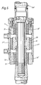
- this requires a change in the articulation area of the handlebars 24 on the axle body 15 compared to the conventional design. In the embodiment of Figures 4 and 5, this scope of change is completely shifted into the handlebars 24 'so that the articulation points can remain unchanged in the area of the axle body 15 compared to a conventional omnibus training.
- the cylinder 27 or 27 ' is connected to the piston 26 via an all-round adherent annular rubber intermediate layer, which serves as a rubber spring 30 and which also causes the piston seal within the cylinder 27 or 27'. Precise and smooth machining of the piston and the cylinder inner wall is not necessary.
- the piston rods 31, which are designed as sleeves, are connected to the likewise cylindrical cylinder covers 32 via an annular rubber intermediate layer; the The intermediate rubber layer is vulcanized on both parts 31 and 32.
- the cylinder cover 32 and the piston 26 each form end stops.
- the working spaces enclosed between the cylinder covers and the piston increase or decrease and, accordingly, displace the liquid volume contained therein.
- the two corresponding work areas of the opposite handlebars are interconnected by means of a connecting line 28; what the one working space displaces is taken up accordingly by the other.
- the two work spaces further away from the axle body 15 are also short-circuited by means of a connecting line 28.
- Throttles 29 are installed in the connecting lines 28, so that the displacement of the piston 26 is opposed to a work-consuming resistor. Due to this throttling effect, the piston / cylinder units can take over the function of a yaw vibration brake.
Landscapes
- Engineering & Computer Science (AREA)
- Mechanical Engineering (AREA)
- Chemical & Material Sciences (AREA)
- Combustion & Propulsion (AREA)
- Transportation (AREA)
- Platform Screen Doors And Railroad Systems (AREA)
- Vehicle Body Suspensions (AREA)
Applications Claiming Priority (2)
| Application Number | Priority Date | Filing Date | Title |
|---|---|---|---|
| DE3733295 | 1987-10-02 | ||
| DE3733295A DE3733295C1 (de) | 1987-10-02 | 1987-10-02 | Spurfuehrbarer Omnibus |
Publications (3)
| Publication Number | Publication Date |
|---|---|
| EP0309715A2 true EP0309715A2 (fr) | 1989-04-05 |
| EP0309715A3 EP0309715A3 (en) | 1989-07-26 |
| EP0309715B1 EP0309715B1 (fr) | 1991-05-29 |
Family
ID=6337446
Family Applications (1)
| Application Number | Title | Priority Date | Filing Date |
|---|---|---|---|
| EP88113344A Expired - Lifetime EP0309715B1 (fr) | 1987-10-02 | 1988-08-17 | Autobus guidé sur piste |
Country Status (7)
| Country | Link |
|---|---|
| US (1) | US4869176A (fr) |
| EP (1) | EP0309715B1 (fr) |
| JP (1) | JPH0667733B2 (fr) |
| AU (1) | AU604628B2 (fr) |
| BR (1) | BR8804993A (fr) |
| DE (1) | DE3733295C1 (fr) |
| ES (1) | ES2022961B3 (fr) |
Families Citing this family (6)
| Publication number | Priority date | Publication date | Assignee | Title |
|---|---|---|---|---|
| JPH10100894A (ja) * | 1996-09-25 | 1998-04-21 | Hino Motors Ltd | ガイドウェイ車輛のステアリング機構 |
| DE102007050794A1 (de) * | 2007-10-24 | 2009-04-30 | Audi Ag | Verstelleinheit für eine verstellbare Radaufhängung eines Kraftfahrzeugs |
| PL219301B1 (pl) | 2010-11-29 | 2015-04-30 | Inst Włókiennictwa | Sposób wytwarzania barierowych materiałów włókienniczych |
| JP6050155B2 (ja) * | 2013-03-11 | 2016-12-21 | 川崎重工業株式会社 | 案内軌条式車両用案内装置、及び案内軌条式車両 |
| CN110116584B (zh) | 2018-02-06 | 2022-03-18 | 比亚迪股份有限公司 | 轨道车辆的驱动桥、轨道车辆和轨道交通系统 |
| US11220149B2 (en) * | 2019-03-13 | 2022-01-11 | Zf Friedrichshafen Ag | Rear axle assembly designed to fit within rear axle envelope |
Family Cites Families (11)
| Publication number | Priority date | Publication date | Assignee | Title |
|---|---|---|---|---|
| DE2643324A1 (de) * | 1976-09-25 | 1978-03-30 | Daimler Benz Ag | Verkehrssystem mit spurfuehrbaren strassengaengigen fahrzeugen |
| DE2719705A1 (de) * | 1976-06-23 | 1978-11-09 | Daimler Benz Ag | Verkehrssystem, insbesondere oepnv-system, mit spurfuehrbaren strassengaengigen fahrzeugen mit einschlagbarer hinterachse |
| DE2813700A1 (de) * | 1978-03-30 | 1979-10-04 | Daimler Benz Ag | Spurfuehrbares fahrzeug mit schwenkbarer hinterachse |
| DE2844626A1 (de) * | 1978-10-13 | 1980-04-24 | Daimler Benz Ag | Mechanisch spurfuehrbares strassengaengiges fahrzeug |
| FR2449017A2 (fr) * | 1978-10-13 | 1980-09-12 | Daimler Benz Ag | Vehicule routier pouvant etre guide mecaniquement sur une voie |
| US4267799A (en) * | 1979-11-01 | 1981-05-19 | Bacon Roger C | Animal training and amusement device |
| JPS5937408Y2 (ja) * | 1980-06-12 | 1984-10-17 | 株式会社神戸製鋼所 | デュアルモ−ド車両の誘導装置 |
| DE3041259C2 (de) * | 1980-11-03 | 1983-01-13 | Daimler-Benz Ag, 7000 Stuttgart | Mechanisch spurführbares oder manuell lenkbares Fahrzeug |
| DE3102094C1 (de) * | 1981-01-23 | 1982-10-28 | Daimler-Benz Ag, 7000 Stuttgart | Spurfuehrbares Kraftfahrzeug |
| DE3103488C2 (de) * | 1981-02-03 | 1987-10-01 | Daimler-Benz Ag, 7000 Stuttgart | Spurführbares Fahrzeug |
| JPS57182557A (en) * | 1981-05-02 | 1982-11-10 | Japan National Railway | Magnetic floating truck |
-
1987
- 1987-10-02 DE DE3733295A patent/DE3733295C1/de not_active Expired
-
1988
- 1988-08-17 EP EP88113344A patent/EP0309715B1/fr not_active Expired - Lifetime
- 1988-08-17 ES ES88113344T patent/ES2022961B3/es not_active Expired - Lifetime
- 1988-09-27 BR BR8804993A patent/BR8804993A/pt not_active IP Right Cessation
- 1988-09-29 JP JP63242660A patent/JPH0667733B2/ja not_active Expired - Fee Related
- 1988-09-30 AU AU23396/88A patent/AU604628B2/en not_active Ceased
- 1988-10-03 US US07/252,118 patent/US4869176A/en not_active Expired - Lifetime
Also Published As
| Publication number | Publication date |
|---|---|
| EP0309715B1 (fr) | 1991-05-29 |
| DE3733295C1 (de) | 1989-01-05 |
| JPH01115764A (ja) | 1989-05-09 |
| BR8804993A (pt) | 1989-05-02 |
| AU604628B2 (en) | 1990-12-20 |
| JPH0667733B2 (ja) | 1994-08-31 |
| ES2022961B3 (es) | 1991-12-16 |
| AU2339688A (en) | 1989-04-06 |
| US4869176A (en) | 1989-09-26 |
| EP0309715A3 (en) | 1989-07-26 |
Similar Documents
| Publication | Publication Date | Title |
|---|---|---|
| DE3744304B4 (de) | Radaufängung für ein lenkbares Rad einer Fahrzeugachse | |
| DE4340557C2 (de) | Radaufhängung | |
| DE3342355C2 (fr) | ||
| DE69517684T2 (de) | Rad-aufhängungssystem | |
| DE3926665C2 (de) | Radaufhängung für Kraftfahrzeuge | |
| DE3331282A1 (de) | Radaufhaengung fuer lenkbare vorderraeder von kraftfahrzeugen | |
| DE1938850B2 (de) | Unabhaengige aufhaengung der gelenkten raeder von kraftfahrzeugen, insbesondere personenkraftwagen | |
| DE3507141C2 (fr) | ||
| EP1080953A1 (fr) | Suspension de roue d'un véhicule automobile à ressort à lame guidant la roue | |
| EP1302342B1 (fr) | Système de suspension d'un essieu oscillant | |
| DE3514823A1 (de) | Unabhaengige radaufhaengung fuer kraftfahrzeuge | |
| DE69008887T2 (de) | Eisenbahnpersonenwagen-Drehgestell. | |
| DE102006004959B4 (de) | Radaufhängung für ein Kraftfahrzeug | |
| DE102017200006A1 (de) | Neigefahrzeug | |
| DE3514146C2 (fr) | ||
| EP2874831B1 (fr) | Suspension de roue pour le pont arrière d'un véhicule | |
| EP0309715B1 (fr) | Autobus guidé sur piste | |
| DE1755462A1 (de) | Achsaufhaengung,insbesondere Hinterachsaufhaengung fuer Kraftfahrzeuge | |
| DE3242930C2 (fr) | ||
| DE10041200B4 (de) | Federbein mit Sturzausgleich | |
| WO2018095656A1 (fr) | Suspension de roue | |
| EP0063370A2 (fr) | Suspension de roues pour véhicule à moteur | |
| DE4405325C1 (de) | Verwendung eines Lenkungsdämpfers als Stabilisierungsvorrichtung für Nachlauflenkachsen | |
| DE4419878C1 (de) | In axialer Richtung bewegliche Achsanordnung für Schienenfahrzeuge | |
| WO2020221569A1 (fr) | Suspension indépendante pour un véhicule à deux voies, essieu et véhicule |
Legal Events
| Date | Code | Title | Description |
|---|---|---|---|
| PUAI | Public reference made under article 153(3) epc to a published international application that has entered the european phase |
Free format text: ORIGINAL CODE: 0009012 |
|
| AK | Designated contracting states |
Kind code of ref document: A2 Designated state(s): ES FR GB IT NL SE |
|
| PUAL | Search report despatched |
Free format text: ORIGINAL CODE: 0009013 |
|
| AK | Designated contracting states |
Kind code of ref document: A3 Designated state(s): ES FR GB IT NL SE |
|
| 17P | Request for examination filed |
Effective date: 19890619 |
|
| 17Q | First examination report despatched |
Effective date: 19901009 |
|
| GRAA | (expected) grant |
Free format text: ORIGINAL CODE: 0009210 |
|
| ITF | It: translation for a ep patent filed | ||
| AK | Designated contracting states |
Kind code of ref document: B1 Designated state(s): ES FR GB IT NL SE |
|
| ET | Fr: translation filed | ||
| GBT | Gb: translation of ep patent filed (gb section 77(6)(a)/1977) | ||
| PLBE | No opposition filed within time limit |
Free format text: ORIGINAL CODE: 0009261 |
|
| STAA | Information on the status of an ep patent application or granted ep patent |
Free format text: STATUS: NO OPPOSITION FILED WITHIN TIME LIMIT |
|
| 26N | No opposition filed | ||
| EAL | Se: european patent in force in sweden |
Ref document number: 88113344.1 |
|
| REG | Reference to a national code |
Ref country code: FR Ref legal event code: TP |
|
| NLS | Nl: assignments of ep-patents |
Owner name: DAIMLERCHRYSLER AG |
|
| REG | Reference to a national code |
Ref country code: GB Ref legal event code: 732E |
|
| REG | Reference to a national code |
Ref country code: GB Ref legal event code: IF02 |
|
| PGFP | Annual fee paid to national office [announced via postgrant information from national office to epo] |
Ref country code: SE Payment date: 20020725 Year of fee payment: 15 Ref country code: NL Payment date: 20020725 Year of fee payment: 15 |
|
| PGFP | Annual fee paid to national office [announced via postgrant information from national office to epo] |
Ref country code: GB Payment date: 20020730 Year of fee payment: 15 |
|
| PGFP | Annual fee paid to national office [announced via postgrant information from national office to epo] |
Ref country code: ES Payment date: 20020809 Year of fee payment: 15 |
|
| PGFP | Annual fee paid to national office [announced via postgrant information from national office to epo] |
Ref country code: FR Payment date: 20020812 Year of fee payment: 15 |
|
| PG25 | Lapsed in a contracting state [announced via postgrant information from national office to epo] |
Ref country code: GB Free format text: LAPSE BECAUSE OF NON-PAYMENT OF DUE FEES Effective date: 20030817 |
|
| PG25 | Lapsed in a contracting state [announced via postgrant information from national office to epo] |
Ref country code: SE Free format text: LAPSE BECAUSE OF NON-PAYMENT OF DUE FEES Effective date: 20030818 Ref country code: ES Free format text: LAPSE BECAUSE OF NON-PAYMENT OF DUE FEES Effective date: 20030818 |
|
| PG25 | Lapsed in a contracting state [announced via postgrant information from national office to epo] |
Ref country code: NL Free format text: LAPSE BECAUSE OF NON-PAYMENT OF DUE FEES Effective date: 20040301 |
|
| EUG | Se: european patent has lapsed | ||
| GBPC | Gb: european patent ceased through non-payment of renewal fee |
Effective date: 20030817 |
|
| PG25 | Lapsed in a contracting state [announced via postgrant information from national office to epo] |
Ref country code: FR Free format text: LAPSE BECAUSE OF NON-PAYMENT OF DUE FEES Effective date: 20040430 |
|
| NLV4 | Nl: lapsed or anulled due to non-payment of the annual fee |
Effective date: 20040301 |
|
| REG | Reference to a national code |
Ref country code: FR Ref legal event code: ST |
|
| REG | Reference to a national code |
Ref country code: ES Ref legal event code: FD2A Effective date: 20030818 |
|
| PG25 | Lapsed in a contracting state [announced via postgrant information from national office to epo] |
Ref country code: IT Free format text: LAPSE BECAUSE OF NON-PAYMENT OF DUE FEES;WARNING: LAPSES OF ITALIAN PATENTS WITH EFFECTIVE DATE BEFORE 2007 MAY HAVE OCCURRED AT ANY TIME BEFORE 2007. THE CORRECT EFFECTIVE DATE MAY BE DIFFERENT FROM THE ONE RECORDED. Effective date: 20050817 |