EP0309967A2 - Systèmes de commande pour groupes motopropulseurs de véhicules - Google Patents
Systèmes de commande pour groupes motopropulseurs de véhicules Download PDFInfo
- Publication number
- EP0309967A2 EP0309967A2 EP88115831A EP88115831A EP0309967A2 EP 0309967 A2 EP0309967 A2 EP 0309967A2 EP 88115831 A EP88115831 A EP 88115831A EP 88115831 A EP88115831 A EP 88115831A EP 0309967 A2 EP0309967 A2 EP 0309967A2
- Authority
- EP
- European Patent Office
- Prior art keywords
- speed change
- controlled variable
- engine
- oil pressure
- operating oil
- Prior art date
- Legal status (The legal status is an assumption and is not a legal conclusion. Google has not performed a legal analysis and makes no representation as to the accuracy of the status listed.)
- Granted
Links
Images


Classifications
-
- B—PERFORMING OPERATIONS; TRANSPORTING
- B60—VEHICLES IN GENERAL
- B60W—CONJOINT CONTROL OF VEHICLE SUB-UNITS OF DIFFERENT TYPE OR DIFFERENT FUNCTION; CONTROL SYSTEMS SPECIALLY ADAPTED FOR HYBRID VEHICLES; ROAD VEHICLE DRIVE CONTROL SYSTEMS FOR PURPOSES NOT RELATED TO THE CONTROL OF A PARTICULAR SUB-UNIT
- B60W30/00—Purposes of road vehicle drive control systems not related to the control of a particular sub-unit, e.g. of systems using conjoint control of vehicle sub-units
- B60W30/18—Propelling the vehicle
-
- B—PERFORMING OPERATIONS; TRANSPORTING
- B60—VEHICLES IN GENERAL
- B60W—CONJOINT CONTROL OF VEHICLE SUB-UNITS OF DIFFERENT TYPE OR DIFFERENT FUNCTION; CONTROL SYSTEMS SPECIALLY ADAPTED FOR HYBRID VEHICLES; ROAD VEHICLE DRIVE CONTROL SYSTEMS FOR PURPOSES NOT RELATED TO THE CONTROL OF A PARTICULAR SUB-UNIT
- B60W10/00—Conjoint control of vehicle sub-units of different type or different function
- B60W10/04—Conjoint control of vehicle sub-units of different type or different function including control of propulsion units
-
- B—PERFORMING OPERATIONS; TRANSPORTING
- B60—VEHICLES IN GENERAL
- B60W—CONJOINT CONTROL OF VEHICLE SUB-UNITS OF DIFFERENT TYPE OR DIFFERENT FUNCTION; CONTROL SYSTEMS SPECIALLY ADAPTED FOR HYBRID VEHICLES; ROAD VEHICLE DRIVE CONTROL SYSTEMS FOR PURPOSES NOT RELATED TO THE CONTROL OF A PARTICULAR SUB-UNIT
- B60W10/00—Conjoint control of vehicle sub-units of different type or different function
- B60W10/10—Conjoint control of vehicle sub-units of different type or different function including control of change-speed gearings
- B60W10/11—Stepped gearings
-
- B—PERFORMING OPERATIONS; TRANSPORTING
- B60—VEHICLES IN GENERAL
- B60W—CONJOINT CONTROL OF VEHICLE SUB-UNITS OF DIFFERENT TYPE OR DIFFERENT FUNCTION; CONTROL SYSTEMS SPECIALLY ADAPTED FOR HYBRID VEHICLES; ROAD VEHICLE DRIVE CONTROL SYSTEMS FOR PURPOSES NOT RELATED TO THE CONTROL OF A PARTICULAR SUB-UNIT
- B60W30/00—Purposes of road vehicle drive control systems not related to the control of a particular sub-unit, e.g. of systems using conjoint control of vehicle sub-units
- B60W30/18—Propelling the vehicle
- B60W30/1819—Propulsion control with control means using analogue circuits, relays or mechanical links
-
- F—MECHANICAL ENGINEERING; LIGHTING; HEATING; WEAPONS; BLASTING
- F16—ENGINEERING ELEMENTS AND UNITS; GENERAL MEASURES FOR PRODUCING AND MAINTAINING EFFECTIVE FUNCTIONING OF MACHINES OR INSTALLATIONS; THERMAL INSULATION IN GENERAL
- F16H—GEARING
- F16H61/00—Control functions within control units of change-speed- or reversing-gearings for conveying rotary motion ; Control of exclusively fluid gearing, friction gearing, gearings with endless flexible members or other particular types of gearing
- F16H61/0021—Generation or control of line pressure
-
- F—MECHANICAL ENGINEERING; LIGHTING; HEATING; WEAPONS; BLASTING
- F16—ENGINEERING ELEMENTS AND UNITS; GENERAL MEASURES FOR PRODUCING AND MAINTAINING EFFECTIVE FUNCTIONING OF MACHINES OR INSTALLATIONS; THERMAL INSULATION IN GENERAL
- F16H—GEARING
- F16H59/00—Control inputs to control units of change-speed- or reversing-gearings for conveying rotary motion
- F16H59/36—Inputs being a function of speed
- F16H59/38—Inputs being a function of speed of gearing elements
- F16H2059/385—Turbine speed
-
- F—MECHANICAL ENGINEERING; LIGHTING; HEATING; WEAPONS; BLASTING
- F16—ENGINEERING ELEMENTS AND UNITS; GENERAL MEASURES FOR PRODUCING AND MAINTAINING EFFECTIVE FUNCTIONING OF MACHINES OR INSTALLATIONS; THERMAL INSULATION IN GENERAL
- F16H—GEARING
- F16H59/00—Control inputs to control units of change-speed- or reversing-gearings for conveying rotary motion
- F16H59/14—Inputs being a function of torque or torque demand
- F16H59/18—Inputs being a function of torque or torque demand dependent on the position of the accelerator pedal
-
- F—MECHANICAL ENGINEERING; LIGHTING; HEATING; WEAPONS; BLASTING
- F16—ENGINEERING ELEMENTS AND UNITS; GENERAL MEASURES FOR PRODUCING AND MAINTAINING EFFECTIVE FUNCTIONING OF MACHINES OR INSTALLATIONS; THERMAL INSULATION IN GENERAL
- F16H—GEARING
- F16H59/00—Control inputs to control units of change-speed- or reversing-gearings for conveying rotary motion
- F16H59/14—Inputs being a function of torque or torque demand
- F16H59/24—Inputs being a function of torque or torque demand dependent on the throttle opening
-
- F—MECHANICAL ENGINEERING; LIGHTING; HEATING; WEAPONS; BLASTING
- F16—ENGINEERING ELEMENTS AND UNITS; GENERAL MEASURES FOR PRODUCING AND MAINTAINING EFFECTIVE FUNCTIONING OF MACHINES OR INSTALLATIONS; THERMAL INSULATION IN GENERAL
- F16H—GEARING
- F16H59/00—Control inputs to control units of change-speed- or reversing-gearings for conveying rotary motion
- F16H59/36—Inputs being a function of speed
- F16H59/44—Inputs being a function of speed dependent on machine speed, e.g. the vehicle speed
-
- F—MECHANICAL ENGINEERING; LIGHTING; HEATING; WEAPONS; BLASTING
- F16—ENGINEERING ELEMENTS AND UNITS; GENERAL MEASURES FOR PRODUCING AND MAINTAINING EFFECTIVE FUNCTIONING OF MACHINES OR INSTALLATIONS; THERMAL INSULATION IN GENERAL
- F16H—GEARING
- F16H59/00—Control inputs to control units of change-speed- or reversing-gearings for conveying rotary motion
- F16H59/68—Inputs being a function of gearing status
- F16H59/70—Inputs being a function of gearing status dependent on the ratio established
Definitions
- the present invention relates generally to control systems for power trains provided in vehicles, and more particularly, to a system for controlling a power train provided in a vehicle and including an engine having an engine output adjusting device, such as a throttle valve, which is controlled through an electric actuator in accordance with a controlled variable on an accelerator accompanying with the engine and an automatic transmission which is coupled with the engine and in which speed change is automatically performed by means of oil pressure produced in an oil hydraulic control circuit for actuating a speed change mechanism and controlled to vary in accordance with the operating condition of the engine.
- an engine output adjusting device such as a throttle valve
- a throttle valve control system for controlling electrically a throttle valve in an engine provided in a vehicle to vary its opening degree in accordance with a controlled variable on an accelerator accompanying with the engine, as disclosed in, for example, the Japanese patent application published before examination under the publication number 59/10751.
- a relation between the opening degree of the throttle valve and the controlled variable on the accelerator can be predetermined to be desirable.
- an automatic transmission which is coupled with an engine provided in the vehicle and includes a torque converter, a power transmitting gear arrangement including a speed change mechanism having engaging friction elements, such as clutch and brake elements, operating with oil pressure, and a hydraulic pressure control device including an oil hydraulic control circuit for causing the speed change mechanism to perform speed change.
- a speed change control according to a predetermined speed change characteristic is carried out in response to variations in engine load and in travelling speed of the vehicle and an operating oil pressure control in which operating oil pressure in the oil hydraulic control circuit is controlled in response to variations in the engine load so as to have a value appropriate to an engine output transmitted to the speed change mechanism in the power transmitting gear arrangement is also carried out to keep selected one or more of the engaging friction elements to be in engagement without shocks of great degree on the occasion of each speed change.
- the engine load is represented by a control variable on an accelerator or an opening degree of a throttle valve.
- the opening degree of the throttle valve is varied suddenly in response to a small variation in the controlled variable on the accelerator under a condition in which the engine operates with an increased rate of variation in the opening degree of the throttle valve to the controlled variable on the accelerator or the opening degree of the throttle valve is varied in response to a speed change operation in the automatic transmission under a condition in which a relation between the opening degree of the throttle valve and the controlled variable on the accelerator is varied in response to each of selected speeds in the automatic transmission. Therefore, it is feared that an undesirable hunting condition in speed change operation in which unnecessary speed changes are repeatedly carried out is brought about due to the variations in the opening degree of the throttle valve caused in such a manner as mentioned above under the speed change control performed in the automatic transmission.
- the throttle valve is controlled by an electric actuator to have an opening degree corresponding to the controlled variable on the accelerator and therefore the engine output is not always in a fixed proportion to the controlled variable on the accelerator in the engine having the throttle valve controlled electrically. Therefore, it is also feared that the operating oil pressure in the oil hydraulic control circuit is not controlled to have a pressure value appropriate to the engine output under the operating oil pressure control performed in the automatic transmission.
- Another object of the present invention is to provide a control system for a power train provided in a vehicle and including an engine having an engine output adjusting device controlled electrically in accordance with a controlled variable on an accelerator accompanying with the engine and an automatic transmission wherein speed change is automatically performed by means of operating oil pressure applied thereto from an oil hydraulic control circuit, in which both a control for speed change in accordance with a travelling condition of the vehicle and a control for operating oil pressure in the oil hydraulic circuit in accordance with an operating condition of the engine are performed favorably in the automatic transmission.
- a further object of the present invention is to provide a control system for a power train provided in a vehicle and including an engine having an engine output adjusting device controlled electrically in accordance with a controlled variable on an accelerator accompanying with the engine and an automatic transmission wherein speed change is automatically performed by means of operating oil pressure supplied thereto from an oil hydraulic control circuit, in which an undesirable hunting condition in speed change operation in which unnecessary speed changes are repeatedly carried out is prevented from being caused under a speed change control and operating oil pressure in the oil hydraulic control circuit is properly controlled to have a pressure value appropriate to an engine output under an operating oil pressure control.
- a control system for a power train provided in a vehicle to include an engine which has an engine output adjusting device controlled through an electric actuator in accordance with a controlled variable on an accelerator accompanying with the engine and an automatic transmission which is coupled with the engine and in which a speed change operation is automatically performed by means of operating oil pressure produced in an oil hydraulic control circuit for actuating a speed change mechanism contained in the automatic transmission to have engaging friction elements and controlled to vary in accordance with an operating condition of the engine, which comprising a first detecting device for detecting the controlled variable on the accelerator, a second detecting device for detecting a controlled variable on the engine output adjusting device, a third detecting device for detecting a travelling speed of the vehicle, a speed change control device for controlling the speed change mechanism to cause the same to carry out the speed change operation based on detection outputs of the first and third detecting devices, and an operating oil pressure control device for controlling the operating oil pressure applied to the engaging friction elements in the speed change mechanism from the oil hydraulic control circuit based on a detection
- a speed change control is carried out in response to variations in the controlled variable on the accelerator represented by the detection output of the first detecting device and variations in the travelling speed of the vehicle represented by the detection output of the third detecting device without causing an undesirable hunting condition in the speed change operation in which unnecessary speed changes are repeatedly carried out, and further, an operating oil pressure control in which the operating oil pressure in the oil hydraulic control circuit is controlled to have a pressure value appropriate to an output of the engine is properly carried out in response to variations in the controlled variable on the engine output adjusting device represented by the detection output of the second detecting device.
- an embodiment of control system for a power train provided in a vehicle according to the present invention which is operative to perform a throttle valve control, a speed change control and an operating oil pressure control, is applied to an engine 1 and an automatic transmission 5 accompanying with the engine 1, which are mounted on a vehicle to constitute a power train.
- the engine 1 is provided with an inlet passage 2 in which a throttle valve 3 is disposed to be movable for adjusting air mass flow passing through the inlet passage 2.
- the throttle valve 3 is driven to vary its opening degree by an electric actuator 4 such as a direct current (DC) motor mounted on the engine 1.
- DC direct current
- the automatic transmission 5 comprises a torque converter portion 6 coupled with the engine 1 and contains a pump impeller, a turbine runner and a stator, a power transmitting gear arrangement portion 7 provided at the output side of the torque converter portion 6, and an oil hydraulic control circuit portion 8 accompanying with the power transmitting gear arrangement portion 7.
- the power transmitting gear arrangement portion 7 includes a speed change mechanism which contains a plurality of engaging friction elements, such as clutch and brake elements, operative with oil pressure to form selectively a plurality power transmitting paths in the power transmitting gear arrangement portion 7.
- the oil hydraulic control circuit portion 8 is provided with solenoid valves 61, 62, 63, 64, 71 and 72 which are controlled by a controller 12 comprising a microcomputer for applying operating oil pressure produced in the oil hydraulic control circuit portion 8 selectively to various elements in the speed change mechanism.
- the electric actuator 4 is supplied with a control signal C T from the controller 12, and the solenoid valves 61 to 64, 71 and 72 are supplied with driving signals C L , C A , C B , C P , C C and C D , respectively, from the controller 12.
- the controller 12 is supplied with a detection output signal Sa obtained from an accelerator position sensor 13 for detecting a controlled variable ⁇ on an accelerator, a detection output signal St obtained from a throttle sensor 14 for detecting an opening degree ⁇ of the throttle valve 3, a detection output signal Sv obtained from a vehicle speed sensor 15 for detecting a travelling speed V of the vehicle, a detection output signal Ss obtained from a turbine speed sensor 16 accompanying with the torque converter 6 for detecting a revolving speed of the turbine runner, that is, a turbine speed ⁇ in the torque converter portion 6, and a detection output signal Sg obtained from a gear position sensor 17 for detecting a gear position G in the power transmitting gear arrangement portion 7.
- a plurality of shift ranges including, for example, P (parking) range, R (reverse) range, N (neutral) range, D (driving) range, 1st range and 2nd range, and a plurality of speeds including, for example, 1st to 4th speeds at the D range, 1st to 3rd speeds at the 2nd range, and 1st and 2nd speeds at the 1st range, are obtained by causing the engaging friction elements contained in the speed change mechanism to work selectively.
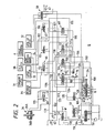
- Fig. 2 shows an example of the oil hydraulic control circuit portion 8 accompanying with the power transmitting gear arrangement portion 7 shown in Fig. 1.
- an oil pump 50 is provided for compressing an operating oil to produce operating oil pressure.
- the operating oil pressure obtained from the oil pump 50 is adjusted to have an appropriate value in a pressure regulator valve 52 and then led through a pressure line 100 and branch lines therefrom to each of a manual shift valve 54, a 1-2 shift valve 55, a coast-exhaust valve 56, a 2-3 shift valve 57, a lock-up control valve 58, a converter relief valve 59 and a servocontrol valve 60 as line pressure.
- the operating oil pressure led to the lock-up control valve 58 is then applied to the torque converter portion 6 and a lock-up clutch 32 accompanying with the torque converter portion 6 as occasion demands.
- the manual shift valve 54 has 1st, 2nd, D, N, R and P shift range positions, each of which is selected by handling manually a shift lever provided for engaging with the power transmitting gear arrangement portion 7, and also output ports a , c , e and f in addition to an input port g connected to the pressure line 100.
- the input port g is permitted to communicate with a forward clutch 31 through the output port a , pressure lines 101 and 111, a forward control valve 65 and a pressure line 112, with a coast clutch 33 through the output port a , the pressure line 101 and 111, a pressure line 113, the coast-exhaust valve 56, a pressure line 115, a coast control valve 68 and a pressure line 116, with an applying chamber 36B of a 2-4 brake device 36 through the output port a , the pressure line 101, the 1-2 shift valve 55 and a pressure line 118, with a releasing chamber 36A of the 2-4 brake device 36 through the output port a , the pressure line 101, a pressure line 119, the servocontrol valve 60 and a pressure line 120, with a low/reverse brake device 34 through the output port e , a pressure line 105, a pressure reducing valve 69, a pressure line 125, the 1-2 shift valve
- the input port g is permitted to communicate with each of the forward clutch 31, the coast clutch 33, and the applying and releasing chambers 36B and 36A of the 2-4 brake device 36 in the same manner as the case in which the manual shift valve 54 is in the 1st shift range position, and also with a 3-4 clutch 38 through the output port c , a pressure line 103, the 2-3 shift valve 57, a pressure line 121, a 3-4 control valve 67 and a pressure line 122.
- the input port g is permitted to communicate with the low/reverse brake device 34 through the output port f , a pressure line 106, the switching valve 70 and the pressure line 126, and with a reverse clutch 35 through the output port f , the pressure line 106 and a reverse control valve 66.
- the input port g is not permitted to communicate with the output ports a , c , e nor f , and therefore each of the forward clutch 31, coast clutch 33, reverse clutch 35, 2-4 brake device 36, 3-4 clutch 38, low/reverse brake device 34 and lock-up clutch 32 is kept in disengagement.
- the operating oil pressure obtained from the oil pump 50 is also led through a pressure line 110 to a pressure reducing valve 53 to be reduced to have a predetermined value therein and then the reduced operating oil pressure from the pressure reducing valve 53 is adjusted to have an appropriate value by each of the solenoid valves 62 and 63.
- the adjusted operating oil pressures obtained from the solenoid valves 62 and 63 are respectively led to the servocontrol valve 60 through a pressure line 131 and to both the reverse control valve 66 and the 3-4 control valve 67 through a pressure line 132.
- the servocontrol valve 60 is operative to adjust the operating oil pressure led thereto through the pressure line 120 from the releasing chamber 36A of the 2-4 brake device 36 and the adjusted operating oil pressure from the servocontrol valve 60 is applied through a pressure line 136 to the coast control valve 68 as pilot pressure and also to the forward control valve 65.
- the 2-3 shift valve 57 receives pilot pressure applied thereto through a pressure line 111a branched from the pressure line 111.
- the pilot pressure toward the 2-3 shift valve 57 is controlled by the solenoid valve 72 so as to be applied to the 2-3 shift valve 57 when the solenoid valve 72 is in its OFF state and so as not to be applied to the 2-3 shift valve 57 when the solenoid valve 72 is in its ON state.
- the pilot pressure which is applied to the 2-3 shift valve 57 is also applied through a pressure line 138 to the 1-2 shift valve 55, and therefore the 1-2 shift valve 55 receives with both the pilot pressure applied thereto through the pressure line 138 and pilot pressure applied thereto through a pressure line 100a branched from the pressure line 100.
- the pilot pressure toward the 1-2 shift valve 55 through the pressure line 100a is controlled by the solenoid valve 71 so as to be applied to the 1-2 shift valve 55 when the solenoid valve 71 is in its OFF state and so as not to be applied to the 1-2 shift valve 55 when the solenoid valve 71 is in its ON state.
- a spool in the 1-2 shift valve 55 is moved to the right in Fig. 2 so that the pressure line 101 is connected with the pressure line 118 regardless of the operation of the solenoid valve 71.
- the pilot pressure controlled by the solenoid valve 71 is applied also to the coast-exhaust valve 56 to which another pilot pressure is applied through the output port e of the manual shift valve 54 and the pressure line 139 when the manual shift valve 54 is in the 1st shift range position.
- the coast-exhaust valve 56 is operative to cause the operating pressure to be applied selectively to the coast clutch 33 in response to application of each pilot pressure thereto.
- the reduced operating oil pressure from the pressure reducing valve 53 is also adjusted by the solenoid valve 61 to be supplied to the lock-up control valve 58 through a pressure line 133 as pilot pressure.
- the solenoid valves 61 to 63 are controlled respectively by the driving signals C L , C A and C B supplied from the controller 12 to be put in the ON state selectively and similarly the solenoid valves 71 and 72 are controlled respectively by the driving signals C C and C D supplied from the controller 12 to be put in the ON state selectively.
- the pilot pressure supplied to the lock-up control valve 58 is adjusted by the solenoid valve 61 to have a predetermined value, the operating oil pressure is applied through the lock-up control valve 58 to the lock-up clutch 32 and thereby a lock-up operation in which the lock-up clutch 32 is caused to be in engagement so as to couple a turbine shaft in the torque converter portion 6 directly with an output shaft of the engine 1 is carried out.
- the reduced operating oil pressure from the pressure reducing valve 53 is further adjusted by the solenoid valve 64 and applied to the pressure regulator valve 52 through a pressure line 134 as pilot pressure.
- the solenoid valves 64 is controlled by the driving signal C P supplied from the controller 12 to be put in the ON state selectively.
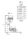
- the pressure reducing valve 53 is provided with a slidable valve spool 53a and a biasing spring 53b for forcing the slidable valve spool 53a to the left in Fig. 3.
- the pressure line 110 from the oil pump 50 is connected to an input port of the pressure reducing valve 53 and the pressure line 134 is connected to an output port of the pressure reducing valve 53, so that the operating oil pressure applied to the pressure reducing valve 53 through the pressure line 110 from the oil pump 50 is affected by the slidable valve spool 53a biased by the biasing spring 53b and the reduced operating oil pressure is obtained in the pressure line 134 to be applied to the pressure regulator valve 52 as the pilot pressure.
- the pressure regulator valve 52 is provided, as shown in Fig. 3, with a slidable main valve spool 52a, a slidable pilot valve spool 52b disposed to align with the slidable main valve spool 52a and to form a pilot pressure chamber 52d at the side opposite to the slidable main valve spool 52a, and a biasing spring 52c provided between the slidable main valve spool 52a and the slidable pilot valve spool 52b to bias the slidable main valve spool 52a to the left in Fig. 3.
- the pressure line 134 is connected to the pilot pressure chamber 52d so that the pilot pressure from the pressure reducing valve 53 is applied to the pilot pressure chamber 52d through the pressure line 134 and the pressure line 100 is coupled with an input port 52e provided on the pressure regulator valve 52. Further, the pressure regulator valve 52 is provided with a drain port 52f.
- the operating oil pressure applied to the input port 52e through the pressure line 100 increases to exceed the pilot pressure applied to the pilot pressure chamber 52d, the slidable main valve spool 52a is moved to cause the drain port 52f to drain a part of the operating oil pressure applied to the input port 52e. Therefore, the operating oil pressure in the pressure line 100 is regulated to be proportional to the pilot pressure applied to the pilot pressure chamber 52d of the pressure regulator valve 52 and applied to various portions as the line pressure.
- the pressure line 134 between the pressure reducing valve 53 and the pressure regulator valve 52 is coupled with the solenoid valve 64 having a drain port 64a as shown in Fig. 3.
- the solenoid valve 64 is operative to vary the pilot pressure applied to the pilot pressure chamber 52d of the pressure regulator valve 52 in accordance with the driving signal C P supplied from the controller 12. Consequently, the operating oil pressure in the pressure line 100 regulated by the pressure regulator valve 52 is controlled to vary in accordance with the driving signal C P supplied to the solenoid valve 64 from the controller 12.
- the controller 12 is operative to produce the control signal C T based on the controlled variable ⁇ on the accelerator represented by the detection output signal Sa, the travelling speed V of the vehicle represented by the detection output signal Sv, and the gear position G in the power transmitting gear arrangement portion 7 represented by the detection output signal Sg to be supplied to the electric actuator 4, so as to perform a throttle valve control in which the throttle valve 3 is controlled to vary its opening degree in accordance with the operating condition of the engine 1.
- the controller 12 is operative also to produce the driving signals C A , C B , C C , C D and C L based on the controlled variable ⁇ on the accelerator represented by the detection output signal Sa, the travelling speed V of the vehicle represented by the detection output signal Sv, and the gear position G in the power transmitting gear arrangement portion 7 represented by the detection output signal Sg to be supplied to the solenoid valves 62, 63, 71, 72 and 61, respectively, so as to perform a speed change control in which the speed change operation and the lock-up operation are carried out without causing a hunting condition in the speed change operation in which unnecessary speed changes arise repeatedly.
- controller 12 is operative to produce the driving signal C P based on the opening degree ⁇ of the throttle valve 3 represented by the detection output signal St and the turbine speed ⁇ in the torque converter portion 6 represented by the detection output signal Ss to be supplied to the solenoid valve 64, so as to perform an operating oil pressure control in which the line pressure in the oil hydraulic control circuit portion 8 is properly controlled to have a pressure value appropriate to an output of the engine 1.
- a rate ⁇ ′ of change in the controlled variable ⁇ on the accelerator is calculated base on the controlled variable on the accelerator represented by the detection output signal Sa stored in the process 21.
- a fundamental throttle opening degree ⁇ n is calculated based on the controlled variable ⁇ on the accelerator represented by the detection output signal Sa so as to satisfy, for example, such a relation to the controlled variable ⁇ on the accelerator as shown with one of curves in Fig. 5 selected in accordance with one of the first and fourth speeds determined by the gear position G which is represented by the detection output signal Sg stored in the process 21.
- the fundamental throttle opening degree ⁇ n which satisfies the relation to the controlled variable ⁇ on the accelerator shown with one of the curves in Fig. 5 is set to increase in response to increment of the controlled variable ⁇ on the accelerator with a first rate of increase, which is relatively large, in a range of relatively small value of the controlled variable ⁇ on the accelerator and a second rate of increase which is smaller than the first rate of increase in a range of ordinary value of the controlled variable on the accelerator with which the vehicle travels stably, as understood from Fig. 5.
- a throttle factor K is calculated base on the rate ⁇ ′ of change in the controlled variable ⁇ on the accelerator and the travelling speed V of the vehicle represented by the detection output signal Sv stored in the process 21.
- the throttle factor K thus obtained is set, for example, to increase in response to increment of the rate ⁇ ′ of change in the controlled variable ⁇ on the accelerator and to have a value between 1.0 and 1.2 as shown in Fig. 6.
- a final throttle opening degree ⁇ o is calculated by multiplying the fundamental throttle opening degree ⁇ n by the throttle factor K, and in process 26, the control signal C T is produced so as to represent the final throttle opening degree ⁇ o calculated in the process 25 and supplied to the electric actuator 4 so that the throttle valve 3 is controlled by the electric actuator 4 to have an actual opening degree corresponding to the final throttle opening degree ⁇ o, and after that the step returns to the process 21.
- the fundamental throttle opening degree ⁇ n is set to increase in response to increment of the controlled variable ⁇ on the accelerator with the relatively large rate of increase in the range of relatively small value of the controlled variable ⁇ on the accelerator, an accelerating characteristic of the vehicle in its start to travel is improved. Further, the fundamental throttle opening degree ⁇ n may be varied also to increase in response to decrement of speed of the engine 1.
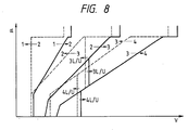
- the detection output signals Sa, Sv and Sg are stored. Then, in process 28, the controlled variable ⁇ on the accelerator represented by the detection output signal Sa stored in the process 27 and the travelling speed V of the vehicle represented by the detection output signal Sv stored in the process 27 are checked up on shifting-up and shifting-down lines in a predetermined speed change characteristic map, for example, as shown in Fig.
- the driving signals C A , C B , C C and C D according to the determination of the shifting of gear position made in the process 28 and the driving signal C L according to the decision concerning the lock-up state made in the process 29 are produced, then the driving signals C A , C B , C C and C D are supplied to the solenoid valves 62, 63, 71 and 72, respectively, for causing the speed change mechanism in the power transmitting gear arrangement portion 7 to conduct a shifting-up or shifting-down operation and the driving signal C L is supplied to the solenoid valve 61 for causing the lock-up clutch 32 accompanying with the torque converter portion 6 to be engaged or disengaged. After that, the step returns to the process 27.
- process 41 the detection output signals St and Ss are stored.
- process 42 a rate ⁇ ′ of change in the opening degree ⁇ of the throttle valve 3 is calculated base on the opening degree ⁇ of the throttle valve 3 represented by the detection output signal St stored in the process 41.
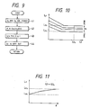
- the target line pressure L P thus obtained is caused to satisfy, for example, such a relation to the turbine speed ⁇ as shown with bent lines in Fig. 10 each of which is selected in accordance with the value of the opening degree ⁇ of the throttle valve 3, and further to satisfy also such a relation to the opening degree ⁇ of the throttle valve 3 as shown with a bent line in Fig. 11 under a condition wherein the turbine speed ⁇ is set to be ⁇ a with which the target line pressure L P is able to vary from L Pb to L Pa as shown in Fig. 10.
- the target line pressure L P calculated as mentioned above is set to have a relatively large value in a range of relatively small value of the turbine speed ⁇ in which the torque converter 6 is operative to perform a torque amplifying operation, compared with a value thereof in a range of relatively large value of the turbine speed ⁇ , as understood from Fig. 10, and also set to increase in response to increment of the opening degree ⁇ of the throttle valve 3, as understood from Fig. 11.
- a rate of increase in a range of relatively small value of the opening degree ⁇ of the throttle valve 3 is larger than that in a range of relatively large value of the opening degree ⁇ of the throttle valve 3.
- the target line pressure L P is further set to increase in response to increment of the rate ⁇ ′ of change in the opening degree ⁇ of the throttle valve 3 when the rate ⁇ ′ of change in the opening degree ⁇ of the throttle valve 3 has a value equal to or larger than a first predetermined value and smaller than a second predetermined value which is larger than the first predetermined value, and to be uninfluenced by the the rate ⁇ ′ of change in the opening degree ⁇ of the throttle valve 3 when the rate ⁇ ′ of change in the opening degree ⁇ of the throttle valve 3 has a value equal to or larger than the second predetermined value.
- the driving signal C P is produced so as to represent the target line pressure L P calculated in the process 43 and supplied to the solenoid valve 64 so that the operating oil pressure in the pressure line 100, which is applied various elements in the speed change mechanism in the power transmitting gear arrangement portion 7 as the line pressure, is controlled through the pressure regulator valve 52 to have a pressure value corresponding to the target line pressure L P and appropriate to the output of the engine 1, and then the step returns to the process 41.
- the operating oil pressure in the pressure line 100 is increased to have the pressure value appropriate to the output of the engine 1 without having any substantial time lag.
- the speed change control is carried out in response to variations in the controlled variable ⁇ on the accelerator and variations in the travelling speed V of the vehicle and therefore an undesirable hunting condition in the speed change operation in which unnecessary speed changes arise repeatedly is prevented from being caused even though the engine 1 operates with an increased rate of variation in the opening degree ⁇ of the throttle valve 3 to the controlled variable ⁇ on the accelerator so that the opening degree ⁇ of the throttle valve 3 is varied suddenly in response to a small variation in the controlled variable ⁇ on the accelerator.
- the operating oil pressure control is carried out in response to variations in the opening degree ⁇ of the throttle valve 3 and therefore the operating oil pressure in the oil hydraulic control circuit portion 8 is properly controlled to have the pressure value appropriate to the output of the engine 1 and thereby to keep selected one or more of the engaging friction elements in the speed change mechanism to be in engagement without shocks of great degree on the occasion of each speed change operation.
Landscapes
- Engineering & Computer Science (AREA)
- Mechanical Engineering (AREA)
- Chemical & Material Sciences (AREA)
- Combustion & Propulsion (AREA)
- Transportation (AREA)
- Automation & Control Theory (AREA)
- General Engineering & Computer Science (AREA)
- Control Of Transmission Device (AREA)
Applications Claiming Priority (2)
| Application Number | Priority Date | Filing Date | Title |
|---|---|---|---|
| JP24156287 | 1987-09-26 | ||
| JP241562/87 | 1987-09-26 |
Publications (3)
| Publication Number | Publication Date |
|---|---|
| EP0309967A2 true EP0309967A2 (fr) | 1989-04-05 |
| EP0309967A3 EP0309967A3 (en) | 1989-10-25 |
| EP0309967B1 EP0309967B1 (fr) | 1994-12-14 |
Family
ID=17076187
Family Applications (1)
| Application Number | Title | Priority Date | Filing Date |
|---|---|---|---|
| EP88115831A Expired - Lifetime EP0309967B1 (fr) | 1987-09-26 | 1988-09-26 | Systèmes de commande pour groupes motopropulseurs de véhicules |
Country Status (3)
| Country | Link |
|---|---|
| US (1) | US5018408A (fr) |
| EP (1) | EP0309967B1 (fr) |
| DE (1) | DE3852456T2 (fr) |
Cited By (1)
| Publication number | Priority date | Publication date | Assignee | Title |
|---|---|---|---|---|
| EP0781944A3 (fr) * | 1995-12-28 | 1998-12-16 | Aisin Aw Co., Ltd. | Système de commande de pression en fonction de la vitesse dans une transmission automatique |
Families Citing this family (21)
| Publication number | Priority date | Publication date | Assignee | Title |
|---|---|---|---|---|
| JPH03249474A (ja) * | 1990-02-27 | 1991-11-07 | Mazda Motor Corp | 加速検出装置及びこれを用いた流体継手の締結力制御装置 |
| JP2868641B2 (ja) * | 1991-03-27 | 1999-03-10 | マツダ株式会社 | 自動変速機の変速制御装置 |
| US5467854A (en) * | 1994-06-07 | 1995-11-21 | Caterpillar Inc. | Method of controlling clutch-to-clutch shifts for a powershift transmission |
| US5505100A (en) * | 1994-09-29 | 1996-04-09 | Caterpillar Inc. | Method of controlling interrupted shifts for a powershift transmission |
| US5551930A (en) * | 1995-04-13 | 1996-09-03 | Caterpillar Inc. | Adaptive control method for an automatic transmission |
| US5580332A (en) * | 1995-04-13 | 1996-12-03 | Caterpillar Inc. | Method for determining the fill time of a transmission clutch |
| JPH08318765A (ja) * | 1995-05-25 | 1996-12-03 | Hitachi Ltd | 情報化自動車制御装置及び方法 |
| US6115661A (en) * | 1998-04-09 | 2000-09-05 | Caterpillar Inc. | End-of-fill detector for a fluid actuated clutch |
| US5950789A (en) * | 1998-04-27 | 1999-09-14 | Caterpillar Inc. | End of fill detector for a fluid actuated clutch |
| KR100353985B1 (ko) * | 1999-12-30 | 2002-09-27 | 현대자동차주식회사 | 차량 급발진 방지 제어 시스템 |
| CA2801334C (fr) * | 2010-06-03 | 2020-03-10 | Polaris Industries Inc. | Commande electronique du papillon des gaz |
| CN102661387B (zh) * | 2012-04-28 | 2015-04-01 | 山推工程机械股份有限公司 | 液力变矩器闭解锁方法、系统及用于牵引工作的工程机械 |
| CN102644729B (zh) * | 2012-04-28 | 2015-07-08 | 山推工程机械股份有限公司 | 液力变矩器闭解锁方法、系统及用于牵引工作的工程机械 |
| CN102635688B (zh) * | 2012-04-28 | 2015-03-11 | 山推工程机械股份有限公司 | 液力变矩器闭解锁方法、系统及用于牵引工作的工程机械 |
| US9205717B2 (en) | 2012-11-07 | 2015-12-08 | Polaris Industries Inc. | Vehicle having suspension with continuous damping control |
| CN107406094B (zh) | 2014-10-31 | 2020-04-14 | 北极星工业有限公司 | 用于控制车辆的系统和方法 |
| CA3043481C (fr) | 2016-11-18 | 2022-07-26 | Polaris Industries Inc. | Vehicule a suspension reglable |
| US10406884B2 (en) | 2017-06-09 | 2019-09-10 | Polaris Industries Inc. | Adjustable vehicle suspension system |
| US10987987B2 (en) | 2018-11-21 | 2021-04-27 | Polaris Industries Inc. | Vehicle having adjustable compression and rebound damping |
| US12397878B2 (en) | 2020-05-20 | 2025-08-26 | Polaris Industries Inc. | Systems and methods of adjustable suspensions for off-road recreational vehicles |
| MX2022015902A (es) | 2020-07-17 | 2023-01-24 | Polaris Inc | Suspensiones ajustables y operacion de vehiculo para vehiculos recreativos todoterreno. |
Family Cites Families (23)
| Publication number | Priority date | Publication date | Assignee | Title |
|---|---|---|---|---|
| JPS4818977B1 (fr) * | 1969-10-14 | 1973-06-09 | ||
| JPS6010224B2 (ja) * | 1979-05-21 | 1985-03-15 | 日産自動車株式会社 | 自動変速機のライン圧制御装置 |
| DE3019562A1 (de) * | 1980-05-22 | 1981-11-26 | Daimler-Benz Ag, 7000 Stuttgart | Vorrichtung zum steuern einer brennkraftmaschine |
| JPH0621584B2 (ja) * | 1982-07-09 | 1994-03-23 | マツダ株式会社 | エンジンのスロツトル弁制御装置 |
| US4470396A (en) * | 1982-12-02 | 1984-09-11 | Mikuni Kogyo Kabushiki Kaisha | Internal combustion engine control system with means for reshaping of command from driver's foot pedal |
| JPS60116953A (ja) * | 1983-11-28 | 1985-06-24 | Mazda Motor Corp | 自動変速機の制御装置 |
| JPS60163731A (ja) * | 1984-02-07 | 1985-08-26 | Nissan Motor Co Ltd | 車速制御装置 |
| DE3443038A1 (de) * | 1984-11-26 | 1986-06-05 | Fujitsu Ltd | Verfahren und vorrichtung zur steuerung des betriebs eines drosselventils |
| JPS61171843A (ja) * | 1985-01-24 | 1986-08-02 | Mazda Motor Corp | エンジンのスロツトル弁制御装置 |
| JPS61207838A (ja) * | 1985-03-12 | 1986-09-16 | Nissan Motor Co Ltd | 車両用アクセル制御装置 |
| JPH0794211B2 (ja) * | 1985-03-28 | 1995-10-11 | アイシン精機株式会社 | クラッチ圧力制御装置 |
| JPS61248960A (ja) * | 1985-04-26 | 1986-11-06 | Mazda Motor Corp | 自動変速機の変速制御装置 |
| US4819163A (en) * | 1985-12-21 | 1989-04-04 | Toyota Jidosha Kabushiki Kaisha | Driving power control system |
| JPS62165537A (ja) * | 1986-01-17 | 1987-07-22 | Komatsu Ltd | スパ−クアシストデイ−ゼルエンジンの吸気装置 |
| JP2507315B2 (ja) * | 1986-03-26 | 1996-06-12 | 株式会社日立製作所 | 内燃機関制御装置 |
| JPH0672563B2 (ja) * | 1986-04-28 | 1994-09-14 | マツダ株式会社 | エンジンのスロツトル弁制御装置 |
| JPH0656113B2 (ja) * | 1986-04-28 | 1994-07-27 | マツダ株式会社 | エンジンのスロツトル弁制御装置 |
| JPS62261634A (ja) * | 1986-05-09 | 1987-11-13 | Nissan Motor Co Ltd | 内燃機関の制御装置 |
| JP2606824B2 (ja) * | 1986-06-06 | 1997-05-07 | 本田技研工業株式会社 | 車載内燃エンジンの絞り弁制御装置 |
| JPS62288343A (ja) * | 1986-06-06 | 1987-12-15 | Honda Motor Co Ltd | 内燃エンジンの絞り弁制御装置 |
| JPH0762450B2 (ja) * | 1986-06-26 | 1995-07-05 | トヨタ自動車株式会社 | 内燃機関のスロツトル弁制御装置 |
| DE3721605A1 (de) * | 1986-07-01 | 1988-01-14 | Mazda Motor | Steuerungssystem fuer verbrennungsmotoren |
| US4799467A (en) * | 1986-07-16 | 1989-01-24 | Honda Giken Kogyo Kabushiki Kaisha | Throttle valve control system for an internal combustion engine |
-
1988
- 1988-09-20 US US07/246,784 patent/US5018408A/en not_active Expired - Fee Related
- 1988-09-26 EP EP88115831A patent/EP0309967B1/fr not_active Expired - Lifetime
- 1988-09-26 DE DE3852456T patent/DE3852456T2/de not_active Expired - Fee Related
Cited By (1)
| Publication number | Priority date | Publication date | Assignee | Title |
|---|---|---|---|---|
| EP0781944A3 (fr) * | 1995-12-28 | 1998-12-16 | Aisin Aw Co., Ltd. | Système de commande de pression en fonction de la vitesse dans une transmission automatique |
Also Published As
| Publication number | Publication date |
|---|---|
| EP0309967B1 (fr) | 1994-12-14 |
| DE3852456D1 (de) | 1995-01-26 |
| US5018408A (en) | 1991-05-28 |
| DE3852456T2 (de) | 1995-05-04 |
| EP0309967A3 (en) | 1989-10-25 |
Similar Documents
| Publication | Publication Date | Title |
|---|---|---|
| EP0309967B1 (fr) | Systèmes de commande pour groupes motopropulseurs de véhicules | |
| US4584906A (en) | Gear shift control for an automatic transmission of a vehicle | |
| US4916979A (en) | On-grade shift logic with provision for skip downshifts | |
| US4697478A (en) | Automatic cruise control system for a motor vehicle | |
| US5611749A (en) | Electronic and hydraulic control system of a 4-speed automatic transmission for automotive vehicle and method for controlling hydraulic pressure | |
| US6056667A (en) | Engaging force control system of a fluid coupling | |
| US5009127A (en) | Transmission ratio control system for a continuously variable transmission | |
| EP0128471A2 (fr) | Dispositif de commande d'une transmission automatique d'un véhicule | |
| US4882952A (en) | Hydraulic control system for automatic transmission with shifting shock reducing means | |
| EP0128470A2 (fr) | Dispositif de commande d'une transmission automatique d'un véhicule | |
| US4858498A (en) | Automatic transmission system for a vehicle | |
| US4645051A (en) | Brake and speed responsive controlled transmission | |
| US5709140A (en) | Hydraulic control device for automatic transmission | |
| JP2655260B2 (ja) | 車両用油圧作動式変速機の制御装置 | |
| US4829852A (en) | Control system for an automatic transmission | |
| JP2593304B2 (ja) | 車両用変速機の制御方法 | |
| US5217086A (en) | Control system for a vehicle | |
| EP0641960B1 (fr) | Dispositif de commande pour transmission de véhicule à commande hydraulique | |
| US5032993A (en) | Control for an automatic transmission | |
| US5150761A (en) | Line pressure arrangement for automotive power train including traction company | |
| JP2715588B2 (ja) | 車両の走行制御装置 | |
| US7048104B2 (en) | Selective bypass of solenoid-controlled supply to friction elements of an automatic transmission | |
| JPH0658150B2 (ja) | 自動変速機の制御装置 | |
| JPS628666B2 (fr) | ||
| JP2927535B2 (ja) | 自動変速機の油圧制御装置 |
Legal Events
| Date | Code | Title | Description |
|---|---|---|---|
| PUAI | Public reference made under article 153(3) epc to a published international application that has entered the european phase |
Free format text: ORIGINAL CODE: 0009012 |
|
| AK | Designated contracting states |
Kind code of ref document: A2 Designated state(s): DE FR GB |
|
| PUAL | Search report despatched |
Free format text: ORIGINAL CODE: 0009013 |
|
| AK | Designated contracting states |
Kind code of ref document: A3 Designated state(s): DE FR GB |
|
| 17P | Request for examination filed |
Effective date: 19891120 |
|
| 17Q | First examination report despatched |
Effective date: 19910227 |
|
| GRAA | (expected) grant |
Free format text: ORIGINAL CODE: 0009210 |
|
| AK | Designated contracting states |
Kind code of ref document: B1 Designated state(s): DE FR GB |
|
| REF | Corresponds to: |
Ref document number: 3852456 Country of ref document: DE Date of ref document: 19950126 |
|
| ET | Fr: translation filed | ||
| PLBE | No opposition filed within time limit |
Free format text: ORIGINAL CODE: 0009261 |
|
| STAA | Information on the status of an ep patent application or granted ep patent |
Free format text: STATUS: NO OPPOSITION FILED WITHIN TIME LIMIT |
|
| 26N | No opposition filed | ||
| PGFP | Annual fee paid to national office [announced via postgrant information from national office to epo] |
Ref country code: FR Payment date: 19980909 Year of fee payment: 11 |
|
| PGFP | Annual fee paid to national office [announced via postgrant information from national office to epo] |
Ref country code: GB Payment date: 19981001 Year of fee payment: 11 |
|
| PGFP | Annual fee paid to national office [announced via postgrant information from national office to epo] |
Ref country code: DE Payment date: 19981005 Year of fee payment: 11 |
|
| PG25 | Lapsed in a contracting state [announced via postgrant information from national office to epo] |
Ref country code: GB Free format text: LAPSE BECAUSE OF NON-PAYMENT OF DUE FEES Effective date: 19990926 |
|
| GBPC | Gb: european patent ceased through non-payment of renewal fee |
Effective date: 19990926 |
|
| PG25 | Lapsed in a contracting state [announced via postgrant information from national office to epo] |
Ref country code: FR Free format text: LAPSE BECAUSE OF NON-PAYMENT OF DUE FEES Effective date: 20000531 |
|
| PG25 | Lapsed in a contracting state [announced via postgrant information from national office to epo] |
Ref country code: DE Free format text: LAPSE BECAUSE OF NON-PAYMENT OF DUE FEES Effective date: 20000701 |
|
| REG | Reference to a national code |
Ref country code: FR Ref legal event code: ST |