EP0310106A2 - Verfahren zum Bilden von Konfigurationsdaten für ein C.N.C.-Bearbeitungsgerät - Google Patents
Verfahren zum Bilden von Konfigurationsdaten für ein C.N.C.-Bearbeitungsgerät Download PDFInfo
- Publication number
- EP0310106A2 EP0310106A2 EP88116169A EP88116169A EP0310106A2 EP 0310106 A2 EP0310106 A2 EP 0310106A2 EP 88116169 A EP88116169 A EP 88116169A EP 88116169 A EP88116169 A EP 88116169A EP 0310106 A2 EP0310106 A2 EP 0310106A2
- Authority
- EP
- European Patent Office
- Prior art keywords
- block
- data
- configuration data
- correction
- remainder
- Prior art date
- Legal status (The legal status is an assumption and is not a legal conclusion. Google has not performed a legal analysis and makes no representation as to the accuracy of the status listed.)
- Withdrawn
Links
Images






Classifications
-
- G—PHYSICS
- G05—CONTROLLING; REGULATING
- G05B—CONTROL OR REGULATING SYSTEMS IN GENERAL; FUNCTIONAL ELEMENTS OF SUCH SYSTEMS; MONITORING OR TESTING ARRANGEMENTS FOR SUCH SYSTEMS OR ELEMENTS
- G05B19/00—Program-control systems
- G05B19/02—Program-control systems electric
- G05B19/18—Numerical control [NC], i.e. automatically operating machines, in particular machine tools, e.g. in a manufacturing environment, so as to execute positioning, movement or co-ordinated operations by means of program data in numerical form
- G05B19/4093—Numerical control [NC], i.e. automatically operating machines, in particular machine tools, e.g. in a manufacturing environment, so as to execute positioning, movement or co-ordinated operations by means of program data in numerical form characterised by part programming, e.g. entry of geometrical information as taken from a technical drawing, combining this with machining and material information to obtain control information, named part program, for the NC machine
- G05B19/40937—Numerical control [NC], i.e. automatically operating machines, in particular machine tools, e.g. in a manufacturing environment, so as to execute positioning, movement or co-ordinated operations by means of program data in numerical form characterised by part programming, e.g. entry of geometrical information as taken from a technical drawing, combining this with machining and material information to obtain control information, named part program, for the NC machine concerning programming of machining or material parameters, pocket machining
- G05B19/40938—Tool management
-
- G—PHYSICS
- G05—CONTROLLING; REGULATING
- G05B—CONTROL OR REGULATING SYSTEMS IN GENERAL; FUNCTIONAL ELEMENTS OF SUCH SYSTEMS; MONITORING OR TESTING ARRANGEMENTS FOR SUCH SYSTEMS OR ELEMENTS
- G05B2219/00—Program-control systems
- G05B2219/30—Nc systems
- G05B2219/35—Nc in input of data, input till input file format
- G05B2219/35401—Tool edge, tool shape, dead corner because of tool shape
-
- Y—GENERAL TAGGING OF NEW TECHNOLOGICAL DEVELOPMENTS; GENERAL TAGGING OF CROSS-SECTIONAL TECHNOLOGIES SPANNING OVER SEVERAL SECTIONS OF THE IPC; TECHNICAL SUBJECTS COVERED BY FORMER USPC CROSS-REFERENCE ART COLLECTIONS [XRACs] AND DIGESTS
- Y02—TECHNOLOGIES OR APPLICATIONS FOR MITIGATION OR ADAPTATION AGAINST CLIMATE CHANGE
- Y02P—CLIMATE CHANGE MITIGATION TECHNOLOGIES IN THE PRODUCTION OR PROCESSING OF GOODS
- Y02P90/00—Enabling technologies with a potential contribution to greenhouse gas [GHG] emissions mitigation
- Y02P90/02—Total factory control, e.g. smart factories, flexible manufacturing systems [FMS] or integrated manufacturing systems [IMS]
Definitions
- This invention relates to a method of automatically forming configuration data for a remainder (described later) which is created in the workpiece because of the edge configuration of the cutting machining tool in a CNC (Computer Numerical Control) machining apparatus.
- a machine tool using a CNC unit is a conventional CNC lathe.
- the CNC lathe receives data on the finally machined configuration (hereinafter referred to as "a final configuration", when applicable) of a work piece to be machined and data on the edge configuration of a cutting tool, to automatically form a machining path for the cutting tool, thereby to machine the workpiece.
- FIG. 1 is an explanatory diagram showing the arrangement of the conventional CNC lathe.
- reference numeral 1 designates a CNC.
- the CNC comprises: a CPU (central processing unit) 2; a memory 3 in which control programs and machining programs have been stored; a keyboard forming input/output means; a CRT (cathode ray tube) 5; and servo drive means including an axial movement control section and a servo amplifier.
- FIG. 7 designates a lather under the control of the CNC.
- the lathe comprises: a chuck 9 for holding a work piece 8; a spindle motor for rotating the work piece 8 through the chuck 9; a cutting tool 11 for machining the work piece 8; a tool holder 12 for holding the cutting tool 11; and two servo motors (not shown) which, under the control of the above-described servo drive means 6, move the cutting tool 11 in the direction of the axis of rotation of the work piece 8; i.e., in the direction of X-axis, and in the direction perpendicular to the direction of X-axis; i.e., in the direction of Z-axis through the tool holder 12, respectively.
- the CPU 2 accesses a control program stored in the memory 3 and processes the commands one by one. Furthermore the CPU 2 accesses a machining program stored in the memory 3 according to the control program, and, according to the machining program, calculates the distance of movement of the cutting tool 11 in the X-Z coordinate plane and applies the distance of movement thus calculated to the servo drive means 6, and pulse-controls the two servo motors (not shown) of the lathe 7 with the aid of the servo drive means 6, to machine the work-piece 8.
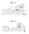
- the workpiece 8 is machined to the edge-corrected configuration which is determined by taking the tool angle into account. For instance when, as shown in FIG.
- a machining path is automatically formed for the cutting tool 11, so that the workpiece 8 is machined.
- annular portion p0-p1-q0 triangular in section remains unmachined (hereinafter referred to as "a remainder", when applicable). Therefore, the configuration data of the remainder are obtained, for instance, by calculation, and inputted through the keyboard 4 in advance, and as shown in FIG. 9 a cutting tool lla whose edge is orientated opposite to the edge of the cutting tool used for the machining of the edge-corrected configuration is moved in the opposite direction so that the remainder of the workpiece 8 is machined.
- an object of this invention is to eliminate the above-described difficulty. More specifically, an object of this invention is to provide a method of automatically forming the configuration data of a remainder which is due to the edge correction of a cutting tool in a CNC machining apparatus.
- a CNC machining apparatus comprises a CNC, a memory, input/output means, and servo drive means is provided, and according to final configuration data inputted for a workpiece, an edge-corrected configuration data block train is formed with the edge configuration of a cutting-tool taken into account, and configuration data are formed for a remainder which is created in the workpiece because of the edge configuration of the cutting tool.
- a correction data block for a correction object when a correction data block for a correction object is formed and added to the edge-corrected configuration block train, a storage data block for storing the final configuration data corresponding to the correction object, and a conversion table for searching for the address of the storage data block with the aid of the index data of the correction data block are formed, and data of the correction data block for the correction object in the edge-corrected configuration data block and of the storage data block corresponding to the correction data obtained through the conversion table are extracted to form configuration data for a remainder which is created in the workpiece because of the edge configuration of the cutting tool.
- the CPU searches the final configuration data block train for a correction object for the cutting tool, and when a correction object is detected, a correction data block is formed and added to the edge-corrected configuration data block train while a storage data block is formed to store the final configuration data corresponding to the correction object, and a conversion table is formed so that the address of the storage data block can be searched with the aid of the index data of the correction data block; and when no correction object is detected, the final configuration data are transferred to complete the edge-corrected configuration data block train.
- the CPU searches the edge-corrected configuration data block train for a correction object, and when a correction object is detected, then correction data are extracted from the corresponding correction data block while the final configuration data are extracted form the storage data block corresponding to the correction object which is obtained through the conversion table, and configuration data are formed for the remainder of the workpiece by utilizing these data thus extracted.
- the final configuration data train is checked for a cutting tool's edge correction object, and when do cutting tool's edge correction object is detected, the final configuration data checked are transferred to the edge-corrected configuration data train; and when a cutting tool's edge correction object is detected, correction data are formed and instead of the final configuration data checked, are transferred to the edge-corrected correction data train, and in formation of the correction data, two data in the final configuration data train which give the data of the start and end points of the correction, the final configuration data existing between the two data, and the correction data are transferred to the remainder data train.
- FIGS. 4 through 9 One preferred embodiment of this invention will be described with reference to FIGS. 4 through 9.
- a CNC lathe is the same as that shown in FIG. 1, and in the following description reference numerals or characters which are the same as those in FIG. 1 designate the same parts.
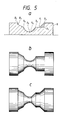
- FIG. 4 is an explanatory diagram showing machining data block trains for the workpiece 8 on which the configuration data of the remainder of the workpiece 8 are formed, in correspondence to the part (a) of FIG. 5 which is an explanatory diagram showing the machining section of the workpiece 8.
- reference character A designates a final configuration data block train according to the final configuration data of the workpiece 8 which have been inputted through the keyboard 4 of the CNC 1.
- the X-Z coordinates of points p0 through p6 in the section of the workpiece 8 as shown in the part a of FIG. 4 are stored in the data blocks P0 through P6, respectively, and configuration data (described later) between the points indicated by each of the blocks, except the first block P0, and the respective preceding blocks are stored.
- reference character B designates an edge-corrected configuration block train which is formed for actual machining by taking the edge configuration of the cutting tool 11 into account according to the above-described final configuration data block train A .
- the X-Z coordinates of points p0, q1, p2, q2, and p3 through p6 shown in the part a of FIG. 5 are stored in data blocks P0, Q1, P2, Q2 and P3 through P6, respectively, and configuration data between the points indicated by each of the blocks, except the first block, and the respective preceding blocks are stored.
- the blocks Q1 and Q2 are those which store correction data prepared for correction objects (hereinafter referred to as "correction data blocks", when applicable), and the blocks P0 through P6 are for other than the correction objects and are obtained by transferring the corresponding blocks of the above-described final configuration data block train A .
- reference character C designates a storage data block train for storing out of the above-described final configuration data block train A the data blocks corresponding to the correction objects of the above-described edge-corrected configuration data block train B . More specifically, during the formation of the above-described edge-corrected configuration data block train B , for instance in response to the formation of the correction data block Q1 for the correction object the corresponding block P1 of the final configuration data block train A which is not transferred to the edge-corrected configuration data block train B and the block P2 including the correction end point which is continuous with the block P1 are stored.
- reference character D designates a conversion table train for reading, in formation of the configuration data of the remainder of the workpiece 8, corresponding blocks of the above-described storage data block train C according to the index information (described later) of the correction data blocks for correction object of the edge-corrected configuration data block train B .
- the part (a) of FIG. 6 is an explanatory diagram showing the structure of an individual data block which is in common with the above-described data block trains A , B and C .
- the data block 13 comprises: a mode part 14; an index part 15; and a data storage part.
- the data storage part 16 stores the X-Z coordinates (x i , z i ) of the point indicated by the block 13, and the configuration data of the line connecting the coordinate point (x i , z i ) and the coordinate point (x i-1 , z i-1 ) of the preceding block.
- the two least significant bits indicate the kind of configuration data stored in the data storage part 16. For instance, "0 1" indicates a straight line, "1 0" a clockwise (concave) arc, and "1 1" a counterclockwise (convex) arc. In the case where the two bits are "0 0", the block is the first one in the block train, and has no data.
- a predetermined bit, or the n-th bit (for instance, the 3rd bit) is utilized as a flag bit.
- the data block is a correction data block.
- the table numbers of the conversion table train D are stored in the order beginning from zero, and the corresponding conversion table can be called.
- FIG. 7 shows the arrangement of each of the tables in the conversion table train D . As shown in FIG.
- a conversion table 17 is made up of a flag part 18, a number part 19, and a pointer 20.
- the pointer 20 stores the address of the corresponding block of the storage data block train C .
- the number of data blocks following the data block having the address specified by the pointer 20 is stored in the number part 19.
- the final configuration data block train A is eliminated after the edge correct configuration data block train B is formed according to the train A , for the purpose of economically using the memory 2. Therefore, the data block, such as the data block P1 of the final configuration data block train A , which is not transferred to the edge-corrected configuration data block train B because of the formation of the correction data block Q1 should be stored separately for formation of the configuration data of the remainder.
- the blocks P2 and P3 following the correction data blocks Q1 and Q2 in the edge-corrected configuration data block train B should also be stored separately for formation of the configuration data of the remainder, because for formation of the configuration data of the remainder it is necessary to process the coordinates of these data blocks; i.e., it is necessary to coincide the coordinates of the blocks P2 and P3 with those of the preceding blocks Q1 and Q2.
- the second step for every correction object of the above-described edge-corrected configuration data block train B , as for the first remainder the correction data block Q1, the preceding data block P0, and the blocks P1 and P2 in the storage data block train C obtained through the conversion table are taken out to form the configuration data of the first remainder, and as for the second remainder the correction data block Q2, the preceding block P2, and the block P3 in the storage data block train C are taken out to form the configuration data of the second remainder.
- FIG. 8 is a flow chart of the above-described first step.
- the final configuration data block train A is searched for a correction object, and the correction block, and the storage data block C and the conversion table D are formed.
- the term "investigation block" is intended to mean a block P n to be checked in the final configuration data block train A .
- the investigation block is set to the first block P0 (Step 23), and then to the next block so that, in practice, the investigation is started with the block P1 (Step 23). It is determined whether or not the block has been investigated (Step 24). If not, it is determined whether or not the investigation block is a correction object (Step 25).
- This determination is carried out by comparison of the gradient a n of a straight line connecting the coordinates p n (x n , z n ) of the investigation block Pn and the coordinates p n-1 (x n-1 , z n-1 ) of the preceding block P n-1 with the tool angle ⁇ of the cutting tool 11.
- ⁇ ⁇ a n it is determined that the investigation block is a correction object.
- the investigation block namely, the final configuration block is transferred to the edge- corrected configuration data block train B , and an edge-corrected configuration data block P n is formed, and then Step 23 is effected again. This step is not shown in the flow chart.
- the block P2 is a correction-ended block.
- the block P2 is stored in the storage data block P2 which follows the storage data block P1 formed previously (Step 30), and a correction data block Q1 is formed. And the n-th bit in the mode part of the correction data block Q1 is set to "1" (ON), thereby to set the flag (Step 31).
- the flag set up is indicated by (*).
- Step 32 a conversion table to search for the address of the above-described storage data block P1 is formed by using the numerical value in the index part of the correction data block Q1 (Step 32, the correction data block Q1 is added to the above-described edge-corrected configuration data block train B , and Step 32 is effected again. This step is not shown.
- the above-described operations are carried out until the investigation block reaches the last stage.
- Step 27 it is determined whether or not the investigation block is a correction-ended block; that is, it is determined whether the coordinate point of the position data included by the block is on one side of the straight line whose gradient is equal to the tool angle ⁇ of the cutting tool or the other side. When the coordinate point is on the left side of the straight line in the part a of FIG. 5, it is determined that the investigation block is a correction-ended block.
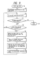
- FIG. 9 is a flow chart showing the second step described above.
- the edge-corrected configuration data block train B is successively searched so that the blocks P1 and P2 of the storage data block train C are taken out by using a correction data block, for instance the block Q1, the preceding block P1, and the index data of the block Q1 with the aid of the conversion table D , thereby to form the configuration data of the remainder of the workpiece 8.
- the term "investigation block” is intended to mean a block to be checked in the edge-corrected configuration data block train B .
- the first block P0 is selected as the investigation block (Step 35), and then the next block is selected; that is, the investigation is started with the block Q1 (Step 36).
- Step 37 It is determined whether or not the block has been investigated (Step 37). If not, it is determined from the flag set in the mode part of the block (indicated by the mark (*) beside the block Q1 or Q2 in the edge-corrected configuration data block train B ) whether or not the block is a correction data block (Step 38). If it is not a correction data block, then Step 36 is effected again.
- the start point p0 of the section of the remainder is obtained from the preceding block P0 (Step 39), and the address of the storage data block P1 is taken out according to the pointer part 19 of the conversion table having the number (0) corresponding to the number (0) of the index part of the correction data block Q1, and the block following the storage data block P1 which corresponds to the numerical value (2) of the number part 20 of the conversion table (0) mentioned above is also taken out.
- the numerical value of the number part 19 of the conversion table 17 is two (2), and therefore the blocks P1 and P2 of the storage data block train C are taken out (Step 40).
- Step 41 The coordinate data of the storage data block P2; i.e., the coordinate data of the last block of the remainder configuration are replaced by those of the correction data block Q1 (Step 41), the remainder's configuration data are calculated by using the data blocks P0, P1, P2 and Q1 (Step 42), and Step 36 is effected again.
- the above-described operations is carried out until the investigation comes to the end.
- the CNC lathe uses the above-described remainder configuration data to automatically form cutting paths for the cutting tool 11, and machines the remainder or remainders created in the workpiece 8.
- the configuration data of the remainder are displayed on the CRT 5, so that the configuration of the remainder can be observed before machining of the workpiece.
- the technical concept of the invention is applied to a CNC lathe; however, it should be noted that the invention is not limited thereto or thereby. That is, the technical concept of the invention is equally applicable to a machine tool such as a planing machine in which a cutting tool is moved relative to the workpiece to machine the latter so that, similarly, the remainder configuration data are formed, the remainder is automatically machined, and the remainder configuration data are displayed.
- a machine tool such as a planing machine in which a cutting tool is moved relative to the workpiece to machine the latter so that, similarly, the remainder configuration data are formed, the remainder is automatically machined, and the remainder configuration data are displayed.
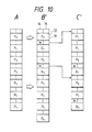
- FIG. 10 is an explanatory diagram showing the relationship among a final configuration data block train, an edge-corrected configuration data train and a remainder configuration data block train, which are necessary for formation of remainder configuration data in the second embodiment of the present invention.
- reference character C ′ designates a remainder data block train storing all the data blocks which are required for formation of remainder configuration data and the same reference characters designate the same data in FIG. 4.
- the remainder data block train stores the correction data blocks Q1 and Q2 in the edge-corrected configuration data block train B′, a pair of data blocks in the final configuration data block train A which are the same as the preceding and following data block thereof, and all the data blocks between the pair of data blocks.
- the remainder data block train stores the data blocks P1, P1, P2 and Q1 with respect to the first correction object, and the data blocks P2, P3 and Q2 with respect to the second correction object.
- the data block trains A, B′ and C′ are stored in the memory 3.
- each data block train are shown in FIGS. 6(a) to 6(c).
- a procedure of forming the configuration data of the remainder of the workpiece 8 in the second embodiment will be described.
- the remainder of the workpiece 8 is the difference between the final configuration of the workpiece 8 shown in the part b of FIG. 5 and the edge correct configuration shown in the part c of FIG. 5.
- a first annular remainder p0-q1-p1 triangular in section and a second annular remainder p2-q2 arcuate in section are formed.
- the configuration data of the first remainder are formed by using the data of the correction data block Q1 of the edge-corrected configuration data block train B ′ and the preceding and following data blocks P0 and P2, and the data of the data block P1 of the final configuration data block train A . That is, the block P0 has the start point coordinates p0 of the section, the block P1 the coordinates p1 and the configuration data of a straight line p0-p1 (perpendicular to the axis of rotation), the block P2 the configuration data of a straight line p1-p2 (parallel to the axis of rotation), and the block Q1 the coordinates q1 and the configuration data of a straight line p0-q1 (the angle of inclination ⁇ ).
- the configuration data of the second remainder are formed by using the data of the correction data block Q2 and the preceding and following blocks P2 and P3. That is, the block P2 has the start point coordinates p2 of the section, the block P3 the configuration data of arc p2p3 (the radius and the center's coordinates), and the block Q2 the coordinates q2 and the configuration data of a straight line p2-q2 (the angle of inclination ⁇ ). These data are used to calculate the configuration data of the second remainder.
- the first step of forming the configuration data of the remainder is as follows: In formation of the edge-corrected configuration data block train B ′, the data blocks corresponding to the correction objects in the final configuration data block train A - for instance, with respect to the first remainder the correction data block Q1 and the blocks P0,P1 and P2 corresponding thereto, and with respect to the second remainder the correction data block Q2 and the blocks P2 and P3 corresponding thereto - are stored with the remainder data block train C formed separately.
- the second step thereof is as follows:
- the remainder data block train C ′ is accessed beginning with the first block, and as for the first remainder the data of all the data blocks P1, P1, P2 and Q1 are read until appearance of the correction data block Q1 the presence of which can be confirmed, and as for the second remainder the data of all the data blocks P2, P3 and Qz are read until appearance of the correction data block Q2 the presence of which can be confirmed, so that the configuration data of the first and second remainders are formed.
- FIG. 11 is a flow chart of the above-described first step.
- the final configuration data block train A is searched for a correction object, and the correction data block and the remainder data block train C ′ are formed.
- the term "investigation block" is intended to mean a block P n to be checked in the final configuration data block train A .
- the investigation block is set to the first block P0 (Step 122), and then to the next block so that, in practice, the investigation is started with the block P1 (Step 123). It is determined whether or not the block has been investigated (Step 124).
- Step 125 it is determined whether or not the investigation block is a correction object. This determination is achieved through comparison of the gradient a n of a straight line connecting the coordinates P n (x n , z n ) of theommegation block P n and the coordinates p n-1 (X n-1 , z n-1 ) of the preceding block P n-1 with the tool angle ⁇ of the cutting tool 11. When a n , it is determined that the investigation block is a correction object.
- it is determined whether or not the investigation block is a correction-ended block (Step 127).
- the investigation block P1 is also stored in the remainder data block train (Step 128), the investigation block is set to the next block P2 (Step 129), and Step 127 is effected again. It is determined again whether or not the investigation block is a correction-ended block.
- the block P2 being a correction-ended block, is stored by transferring it to the remainder data block train C ′ (Step 130), and a correction data block Q1 is formed is formed according to the data blocks P0 through P2. And the n-th bit of the mode part of the correction data block Q1 is set to "1" (ON), thereby to set the flat (Step 131).
- the correction data block Q1 is also stored by transferring it to the remainder data block train C ′. In the remainder data block train C ′ of FIG. 10, the flag set up is indicated by (X).
- Step 127 it is determined whether or not the investigation block is a correction-ended block; that is, it is determined whether the coordinate point of the position data included by the block is on one side of the straight line whose gradient is equal to the tool angle ⁇ of the cutting tool 11 or the other side.
- the coordinate point is on the left side of the straight line, it is determined that the investigation block is a correction-ended block.
- FIG. 12 is a flow chart showing the second step described above.
- the remainder configuration data block train C ′ is searched block by block so that, with the flag (X) of the correction data block Q1 as an index, access is made to the data blocks P0 through Q1, thereby to form configuration data for the remainder created in the workpiece 8.
- the term "investigation block” is intended to mean a block to be checked in the remainder data block train C ′.
- the investigation block is set to the first block P0, and the data of the block P0 is read (Step 137). Then, the investigation block is set to the next block (Step 138), so that it is determined whether or not the block is an investigation-ended block (Step 129).
- Step 140 the data of the investigation block is read (Step 140) and the flag of the investigation block is detected (Step 141). If no flag is set up, Step 138 is effected again; that is, Steps 138 through 141 described above are carried out again. If the flag has been set up, then the investigation block is the correction data block Q1; that is, the data of all the data block P0 through P2 and Q1 for the first remainder have been read, the coordinate data of the data block P2; i.e., those of the correction-ended block are replaced by those of the above-described correction data block Q1 (Step 142), configuration data are calculated from the above-described data for the first remainder (Step 143), and Step 138 is effected again. The above-described operations are carried out until the investigation comes to the end.
- the remainder data block train C ′ is accessed block by block, and the remainder's data are calculated according to the data obtained through the access.
- a method in which, in the first step, the remainder data block train C ′ is made more complete so that when, in the second step, access is made to the remainder data block train C ′, configuration data can be immediately obtained for the remainder will be described, as another embodiment of the invention, with reference to FIG. 13.
- the coordinate data of the correction data block is transferred to the coordinate data part of the preceding correction and point data block as shown in FIG. 13 (Step 145).
- the coordinate data q1 of the block Q1 is transferred to the coordinate data part of the block P2; and for the second remainder, the coordinate data Q2 of the block Q2 is transferred to the coordinate data part of the block P3.
- the coordinate data of the first data block of each of the remainders is transferred to the coordinate data part of the last correction data block (Step 146).
- the coordinate data P0 of the block P0 is transferred to the coordinate data part of the block Q1; and for the second remainder, the coordinate data P2 of the block P2 is transferred to the coordinate data part of the block Q2.
- Step 147 the most significant bit in the mode part 14 of the last data block of each of the remainders is set to "1"; that is, a completion flag indicating the last block of the data block train for each of the remainders is set up (Step 147).
- the most significant bit in the mode part 14 of each of the blocks Q1 and Q2 is set to "1".
- the results of execution of Step 147 are indicated by ( ⁇ ).
- the two least significant bits in the mode part of the first data block for each of the remainders are set to "0 0", thus indicating that that data block is the first data block including the start point coordinates of the remainder (Step 148). This will be described concretely.
- the two least significant bits in the mode part of the first data block P0 for the first remainder are originally "0 0", and therefore Step 148 may be omitted for the first remainder.
- the two least significant bits in the mode part of the first data block P2 are "0 1", and therefore they are rewritten into "0 0".
- the results of execution are indicated by (0).
- the coordinate data indicating the coordinate point q1, and the configuration data of the straight line connecting the coordinate point q1 and the preceding coordinate point p1 are stored in the data block P2 of the first remainder, and the coordinate data of the end point P0 which is equal to that of the start point P0 of the block P0; and the configuration data of the straight line connecting the point P0 and the preceding coordinate point q1 are stored in the data block Q1.
- the coordinate data indicating the coordinate point q2 and the configuration data of the straight line connecting the coordinate point q2 and the preceding coordinate point p2 are stored in the data block P3 of the second remainder; and the coordinate data of the end point p2 which is the same as that of the start point p2 of the block P2, and the configuration data of the straight line connecting the point p2 and the preceding coordinate point q2 are stored.
- the first block of the data block train for each of the remainders can be detected from the fact that the two least significant bits in the mode part 14 of the block are "0 0", and the last block can be detected from the completion flag in the mode part thereof.
- configuration data are formed for all the remainders which are created in the work-piece 8 because of the edge correction. Therefore, the CNC lathe utilizes the remainder configuration data to automatically form machining paths for the cutting tool 11, thereby to machine the remainders created in the workpiece 8.
- the remainder configuration data are displayed on the CRT 5, so that they can be confirmed before machining of the workpiece.
- the technical concept of the invention is applied to a CNC lathe; however, it should be noted that the invention is not limited thereto or thereby. That is, the technical concept of the invention is equally applicable to a machine tool such as a planning machine in which a cutting tool is moved relative to the workpiece to machine the latter so that, similarly, the remainder configuration data are formed, the remainder is automatically machined, and the remainder configuration data are displayed.
- a machine tool such as a planning machine in which a cutting tool is moved relative to the workpiece to machine the latter so that, similarly, the remainder configuration data are formed, the remainder is automatically machined, and the remainder configuration data are displayed.
- the configuration data of a remainder created in the workpiece because of the edge configuration of the cutting tool are automatically formed, which eliminates the difficulty that the configuration data of the remainder must be separately calculated and inputted in order to remove the remainder.
Landscapes
- Engineering & Computer Science (AREA)
- Manufacturing & Machinery (AREA)
- Physics & Mathematics (AREA)
- Geometry (AREA)
- Human Computer Interaction (AREA)
- General Physics & Mathematics (AREA)
- Automation & Control Theory (AREA)
- Numerical Control (AREA)
Applications Claiming Priority (4)
| Application Number | Priority Date | Filing Date | Title |
|---|---|---|---|
| JP249222/87 | 1987-10-02 | ||
| JP24922387 | 1987-10-02 | ||
| JP24922287 | 1987-10-02 | ||
| JP249223/87 | 1987-10-02 |
Publications (2)
| Publication Number | Publication Date |
|---|---|
| EP0310106A2 true EP0310106A2 (de) | 1989-04-05 |
| EP0310106A3 EP0310106A3 (de) | 1989-05-24 |
Family
ID=26539165
Family Applications (1)
| Application Number | Title | Priority Date | Filing Date |
|---|---|---|---|
| EP88116169A Withdrawn EP0310106A3 (de) | 1987-10-02 | 1988-09-30 | Verfahren zum Bilden von Konfigurationsdaten für ein C.N.C.-Bearbeitungsgerät |
Country Status (3)
| Country | Link |
|---|---|
| US (1) | US5014209A (de) |
| EP (1) | EP0310106A3 (de) |
| AU (1) | AU620566B2 (de) |
Cited By (1)
| Publication number | Priority date | Publication date | Assignee | Title |
|---|---|---|---|---|
| EP0592687A4 (en) * | 1992-04-22 | 1994-08-10 | Fanuc Ltd | Method of defining machining |
Families Citing this family (4)
| Publication number | Priority date | Publication date | Assignee | Title |
|---|---|---|---|---|
| GB1292612A (en) * | 1969-02-13 | 1972-10-11 | Bamford Excavators Ltd | Improvements relating to earth working implements |
| JP2584104B2 (ja) * | 1990-05-31 | 1997-02-19 | オークマ株式会社 | 砥石形状定義装置 |
| KR101535305B1 (ko) * | 2009-10-09 | 2015-07-08 | 두산인프라코어 주식회사 | 선삭 가공 시스템에서의 공구 경로 생성 방법 |
| KR20160019936A (ko) * | 2013-09-13 | 2016-02-22 | 마키노 밀링 머신 주식회사 | 공구경로 생성방법 및 공구경로 생성장치 |
Family Cites Families (9)
| Publication number | Priority date | Publication date | Assignee | Title |
|---|---|---|---|---|
| AU6339680A (en) * | 1979-10-02 | 1981-04-28 | Daihatsu Motor Co. Ltd. | Method of controlling numerical controlled machine tool |
| US4445182A (en) * | 1979-10-02 | 1984-04-24 | Daihatsu Motor Company, Limited | Method of control of NC machine tools |
| JPS57161906A (en) * | 1981-03-30 | 1982-10-05 | Fanuc Ltd | Correction system for diameter of tool |
| JPS57166606A (en) * | 1981-04-04 | 1982-10-14 | Fanuc Ltd | Numerical control working method |
| JPS57194855A (en) * | 1981-05-27 | 1982-11-30 | Fanuc Ltd | Numerical control system |
| JPS58181105A (ja) * | 1982-04-16 | 1983-10-22 | Fanuc Ltd | 工具径補正方式 |
| JPS5949608A (ja) * | 1982-09-14 | 1984-03-22 | Mitsubishi Electric Corp | 数値制御加工方式 |
| JPS59127108A (ja) * | 1983-01-11 | 1984-07-21 | Mitsubishi Electric Corp | 数値制御装置 |
| FR2544242B1 (fr) * | 1983-04-12 | 1986-11-28 | Num Sa | Procede d'usinage d'un profil fini et dispositif de mise en oeuvre du procede |
-
1988
- 1988-09-30 EP EP88116169A patent/EP0310106A3/de not_active Withdrawn
- 1988-10-03 US US07/252,213 patent/US5014209A/en not_active Expired - Lifetime
- 1988-10-04 AU AU23388/88A patent/AU620566B2/en not_active Ceased
Cited By (2)
| Publication number | Priority date | Publication date | Assignee | Title |
|---|---|---|---|---|
| EP0592687A4 (en) * | 1992-04-22 | 1994-08-10 | Fanuc Ltd | Method of defining machining |
| US5471394A (en) * | 1992-04-22 | 1995-11-28 | Fanuc Ltd. | Method for defining machining areas of a workpiece |
Also Published As
| Publication number | Publication date |
|---|---|
| EP0310106A3 (de) | 1989-05-24 |
| AU2338888A (en) | 1989-04-06 |
| US5014209A (en) | 1991-05-07 |
| AU620566B2 (en) | 1992-02-20 |
Similar Documents
| Publication | Publication Date | Title |
|---|---|---|
| US4445182A (en) | Method of control of NC machine tools | |
| US4591989A (en) | System for displaying tool parameters of tools utilized in a machining process | |
| JPH0238342B2 (de) | ||
| JPS6257852A (ja) | 自動プログラミング装置 | |
| JPH028855B2 (de) | ||
| US4713747A (en) | Numerically controlled machining method using primary and compensating cutters | |
| US5014209A (en) | Method of forming configuration data for CNC machining apparatus | |
| GB2062293A (en) | Method of control of NC machine tools | |
| JPH0741442B2 (ja) | 工具補正量入力機能を有する数値制御装置 | |
| JPH04256550A (ja) | 切削工具刃先検出装置 | |
| JPH10113836A (ja) | Nc工作機械の使用工具チェック方法および装置 | |
| US5654618A (en) | Process for the two-dimensional determination of a work-area contour for lathes | |
| JPH0753336B2 (ja) | 工作機械の工具自動選択装置 | |
| JPS61173842A (ja) | 数値制御装置 | |
| EP0144435B1 (de) | Numerische steuerungsvorrichtung mit selbsttätiger werkzeugbestimmungsfunktion | |
| JPH0418985B2 (de) | ||
| JPS6149068B2 (de) | ||
| JP2646034B2 (ja) | 数値制御装置 | |
| JP3120263B2 (ja) | 対向主軸旋盤における加工プログラム作成方法 | |
| JPH05158515A (ja) | 工具旋回軸付きnc切削機械のオフセット補正方法 | |
| JPH0732247A (ja) | センタワークにおける熱変位補正方法 | |
| JPS62236642A (ja) | Nc旋盤の工具自動段取り装置 | |
| JPH0616978B2 (ja) | 自動プログラミングにおける4軸同時加工生成方法 | |
| JPS59192440A (ja) | 数値制御加工再開制御装置 | |
| JPS60201860A (ja) | 数値制御工作機械における寸法許容差加工の加工制御方法 |
Legal Events
| Date | Code | Title | Description |
|---|---|---|---|
| PUAI | Public reference made under article 153(3) epc to a published international application that has entered the european phase |
Free format text: ORIGINAL CODE: 0009012 |
|
| PUAL | Search report despatched |
Free format text: ORIGINAL CODE: 0009013 |
|
| AK | Designated contracting states |
Kind code of ref document: A2 Designated state(s): DE FR GB |
|
| AK | Designated contracting states |
Kind code of ref document: A3 Designated state(s): DE FR GB |
|
| RIN1 | Information on inventor provided before grant (corrected) |
Inventor name: KOIKAWA, SHIGERU C/O MITSU. DENKI K.K NAGOYA WORK Inventor name: NANKAKU, SHIGEKI C/O MITSU. DENKI K.K NAGOYA WORKS |
|
| RAP1 | Party data changed (applicant data changed or rights of an application transferred) |
Owner name: MITSUBISHI DENKI KABUSHIKIKAISHA |
|
| 17P | Request for examination filed |
Effective date: 19890725 |
|
| 17Q | First examination report despatched |
Effective date: 19911025 |
|
| STAA | Information on the status of an ep patent application or granted ep patent |
Free format text: STATUS: THE APPLICATION IS DEEMED TO BE WITHDRAWN |
|
| 18D | Application deemed to be withdrawn |
Effective date: 19930309 |