EP0310235A2 - Einrichtung zum Nachführen eines Laserstrahl-Interferometers - Google Patents
Einrichtung zum Nachführen eines Laserstrahl-Interferometers Download PDFInfo
- Publication number
- EP0310235A2 EP0310235A2 EP88307555A EP88307555A EP0310235A2 EP 0310235 A2 EP0310235 A2 EP 0310235A2 EP 88307555 A EP88307555 A EP 88307555A EP 88307555 A EP88307555 A EP 88307555A EP 0310235 A2 EP0310235 A2 EP 0310235A2
- Authority
- EP
- European Patent Office
- Prior art keywords
- axis
- laser beam
- support
- retroreflector
- tracking system
- Prior art date
- Legal status (The legal status is an assumption and is not a legal conclusion. Google has not performed a legal analysis and makes no representation as to the accuracy of the status listed.)
- Withdrawn
Links
Images



Classifications
-
- G—PHYSICS
- G01—MEASURING; TESTING
- G01S—RADIO DIRECTION-FINDING; RADIO NAVIGATION; DETERMINING DISTANCE OR VELOCITY BY USE OF RADIO WAVES; LOCATING OR PRESENCE-DETECTING BY USE OF THE REFLECTION OR RERADIATION OF RADIO WAVES; ANALOGOUS ARRANGEMENTS USING OTHER WAVES
- G01S7/00—Details of systems according to groups G01S13/00, G01S15/00, G01S17/00
- G01S7/48—Details of systems according to groups G01S13/00, G01S15/00, G01S17/00 of systems according to group G01S17/00
- G01S7/481—Constructional features, e.g. arrangements of optical elements
- G01S7/4811—Constructional features, e.g. arrangements of optical elements common to transmitter and receiver
-
- G—PHYSICS
- G01—MEASURING; TESTING
- G01B—MEASURING LENGTH, THICKNESS OR SIMILAR LINEAR DIMENSIONS; MEASURING ANGLES; MEASURING AREAS; MEASURING IRREGULARITIES OF SURFACES OR CONTOURS
- G01B9/00—Measuring instruments characterised by the use of optical techniques
- G01B9/02—Interferometers
-
- G—PHYSICS
- G01—MEASURING; TESTING
- G01S—RADIO DIRECTION-FINDING; RADIO NAVIGATION; DETERMINING DISTANCE OR VELOCITY BY USE OF RADIO WAVES; LOCATING OR PRESENCE-DETECTING BY USE OF THE REFLECTION OR RERADIATION OF RADIO WAVES; ANALOGOUS ARRANGEMENTS USING OTHER WAVES
- G01S17/00—Systems using the reflection or reradiation of electromagnetic waves other than radio waves, e.g. lidar systems
- G01S17/66—Tracking systems using electromagnetic waves other than radio waves
-
- G—PHYSICS
- G01—MEASURING; TESTING
- G01S—RADIO DIRECTION-FINDING; RADIO NAVIGATION; DETERMINING DISTANCE OR VELOCITY BY USE OF RADIO WAVES; LOCATING OR PRESENCE-DETECTING BY USE OF THE REFLECTION OR RERADIATION OF RADIO WAVES; ANALOGOUS ARRANGEMENTS USING OTHER WAVES
- G01S7/00—Details of systems according to groups G01S13/00, G01S15/00, G01S17/00
- G01S7/48—Details of systems according to groups G01S13/00, G01S15/00, G01S17/00 of systems according to group G01S17/00
- G01S7/481—Constructional features, e.g. arrangements of optical elements
- G01S7/4811—Constructional features, e.g. arrangements of optical elements common to transmitter and receiver
- G01S7/4812—Constructional features, e.g. arrangements of optical elements common to transmitter and receiver transmitted and received beams following a coaxial path
-
- G—PHYSICS
- G01—MEASURING; TESTING
- G01B—MEASURING LENGTH, THICKNESS OR SIMILAR LINEAR DIMENSIONS; MEASURING ANGLES; MEASURING AREAS; MEASURING IRREGULARITIES OF SURFACES OR CONTOURS
- G01B2290/00—Aspects of interferometers not specifically covered by any group under G01B9/02
- G01B2290/70—Using polarization in the interferometer
-
- G—PHYSICS
- G01—MEASURING; TESTING
- G01S—RADIO DIRECTION-FINDING; RADIO NAVIGATION; DETERMINING DISTANCE OR VELOCITY BY USE OF RADIO WAVES; LOCATING OR PRESENCE-DETECTING BY USE OF THE REFLECTION OR RERADIATION OF RADIO WAVES; ANALOGOUS ARRANGEMENTS USING OTHER WAVES
- G01S13/00—Systems using the reflection or reradiation of radio waves, e.g. radar systems; Analogous systems using reflection or reradiation of waves whose nature or wavelength is irrelevant or unspecified
- G01S13/02—Systems using reflection of radio waves, e.g. primary radar systems; Analogous systems
- G01S13/06—Systems determining position data of a target
- G01S13/46—Indirect determination of position data
- G01S2013/466—Indirect determination of position data by Trilateration, i.e. two antennas or two sensors determine separately the distance to a target, whereby with the knowledge of the baseline length, i.e. the distance between the antennas or sensors, the position data of the target is determined
Definitions
- the invention relates to a system for tracking a randomly moving object using a laser beam and first and second beam steering assemblies, which pivot, respectively, about substantially perpendicular and intersecting X and Y axes.
- the steering assemblies direct the laser beam along an R axis, which is perpendicular to the X axis and intersects the X and Y axes, towards a retroreflector coupled to the moving object.
- the system includes an interferometer to determine the distance of the object from a reference location.
- the first beam steering assembly comprises two prisms and the second beam steering assembly comprises a third prism.
- the system can be used to control and calibrate robotic devices, inspect large critical parts, and control machine tool operations and laser welding.
- Systems for tracking moving objects have utility in various technical fields. Thus, they can be used to control and calibrate robotic devices, inspect large critical parts such as dish antennas, air frames and propellers, and control machine tool operations and laser welding.
- these systems typically utilize distance measuring devices, such as laser interferometers, to determine the distance at any point in time of the object relative to a reference location.
- the precise location of the moving object in a volume is typically determined using three tracking and distance measuring devices and the well-known trilateration method. Adding additional structure can also provide the relative angle of the moving object.
- One type of system utilizes gimballed flat mirrors to steer beams of radiation and servo-controlled motors to vary the angular position of the mirrors relative to the object.
- These gimballed mirrors are accurate only to about 20-50 microns with respect to a volume of about 100 cubic meters.
- the accuracy of these systems is limited by bearing and shaft alignment errors, known as run out errors, and by the initial alignment error of the laser beam and the precise center of the mirror.
- these gimballed mirrors afford only limited tilt angles and require frequent recalibration.
- Additional systems utilize reflective pellicles which are formed from very thin reflecting membranes, the thickness being on the order of several microns.
- these pellicles are not rugged and are difficult to work with since they tend to vibrate.
- a primary object of the invention is to provide a tracking laser interferometer that can track a moving object and determine its distance from a reference location with a very high degree of accuracy.
- Another object of the invention is to provide a tracking laser interferometer having an accuracy of about one micron per 100 cubic meters and where cosine errors are on the order of about 0.1 micron.
- a further object of the invention is to provide a tracking laser interferometer that is light, compact, portable, and rugged.
- Another object of the invention is to provide a tracking laser interferometer having relatively wide tracking angles and in which the initial alignment of the laser is not acutely critical.
- Another object of the invention is to provide a laser tracking system which is an improvement over single mirror systems by limiting the error introduced by initial laser misalignment and by directing the laser beam to an optical point in space defined by intersecting axes.
- a tracking system for continually tracking a moving object relative to a reference location, the combination comprising a retroreflector rigidly coupled to the object; a rigid stationary base positioned at the reference location; a first support; a mechanism for pivotally coupling the first support to the base for pivotal movement about a Y axis; a second support; a mechanism for pivotably coupling the second support to the first support for pivotal movement about an X axis, the X and Y axes being substantially perpendicular and intersecting at a point A; a mechanism for generating a laser beam directed along the Y axis towards point A; a first reflective assembly, rigidly coupled to the first support, for receiving the laser beam extending along the Y axis before it intersects the X axis and redirecting the laser beam along the X axis towards point A; a second reflective assembly, rigidly coupled to the second support, for (a) receiving the redirected laser beam along the X axis
- a method of continually tracking a moving object relative to X and Y axes which are perpendicular and intersect at a point A at a reference location comprising the steps of rigidly coupling a retroreflector to the object, directing a laser beam along the Y axis towards the X axis, redirecting the laser beam from the Y axis, before the beam intersects the X axis, along the X axis, redirecting the laser beam from the X axis at point A along an R axis incident on the retroreflector, the R axis being substantially perpendicular to the X axis and intersecting the X and Y axes at point A, generating an error signal from the displacement of the laser beam after incidence of the laser beam on the retroreflector representing movement of the retroreflector and object relative to the X and Y axes, and relocating the R axis relative to the retroreflector and object so as to reduce the
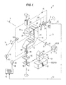
- the tracking laser interferometer system 10 in accordance with the invention is intended to track a moving object and also determine its distance from a reference location.
- System 10 basically comprises a laser 12 capable of generating a laser beam 14 and first and second beam steering assemblies 16 and 18.
- the steering assemblies 16 and 18 pivot, respectively, about substantially perpendicular and intersecting X and Y axes and direct the laser beam 14 along an R axis, which is perpendicular to the X axis and intersects the X and Y axes.
- the laser beam is intercepted by a retroreflector 20, which is coupled to the moving object 22 (Fig. 4) and which returns the laser beam to a position sensitive photodetector 24 via the steering assemblies.
- the photodetector generates an error signal based on lateral displacement of the laser beam and representative of the object's movement relative to the X and Y axes, and this signal is transmitted to two motors 26 and 28 which pivot the steering assemblies about the X and Y axes to reduce the error to zero.
- the system 10 includes an interferometer 30 which utilizes the laser beam 14 to determine the distance of the object from a reference location.
- the first beam steering assembly 16 includes two prisms 32 and 34 which redirect the laser beam 14 through three 90° reflections from an initial direction parallel to the Y axis and towards the X axis to an intermediate direction along the X axis and towards the Y axis.
- the second beam steering assembly 18 includes a third prism 36 which redirects the laser beam through one 90° reflection from the intermediate direction along the X axis to one coincident with the R axis where it is intercepted by the retroreflector 20 and returned to the prism 36 and then photodetector 24.
- the overall system 10 comprises a rigid stationary base 40, the first and second beam steering assemblies 16 and 18 pivotably coupled to the base, first and second servo-controlled motive assemblies including motors 26 and 28 to pivot respectively the first and second beam steering assemblies, a detection assembly comprising photodetector 24, and a control system 42 for receiving an error signal from the photodetector and providing the necessary signals for actuating motors 26 and 28.
- the stationary base 40 forms a reference location and comprises a series of four horizontally extending vertically aligned brackets 44, 46, 48 and 50.
- the first bracket 44 has a vertical bore 52 coaxial with the Y axis and likewise the second bracket 46 has a vertical bore 54 which is coaxial with the Y axis.
- the second bracket 46 also has a horizontal passageway 56 formed in its front face and extending rearwardly as seen in Fig. 3 into communication with bore 54.
- a ball bearing 58 is also rigidly secured inside bore 54 and coaxial therewith.
- the third bracket 48 has a suitable vertical bore located therein and rigidly receiving a ball bearing 60 which is coaxial with the Y axis.
- a similar bore and ball bearing, not shown, is likewise provided in the fourth bracket 50.
- the ball bearings are preferably coupled to the base by set screws.
- the first beam steering assembly 16 comprises a first support 62, an upper tubular shaft 64, a lower tubular shaft 66, and a first reflective assembly 68, all of which pivot about the Y axis through about ⁇ 90°.
- the first support 62 is advantageously in the form of a parallelopiped housing or case and, while not shown, can include a left and right front cover separated by a slit and a rear cover. These covers reduce the possibility of outside interference with the laser beam activity therein.
- the first support 62 thus comprises an upper wall 70, a lower wall 72, a right side wall 74, and a left side wall 76.
- the upper wall 70 has a suitable vertically oriented bore receiving ball bearing 78 rigidly therein, the inner race thereof being rigidly connected to the upper shaft 64.
- the upper wall 70 has an inwardly extending slot 80 therein as seen in Fig. 2 to allow the laser beam to be angled upwardly through at least 60° when the second beam steering assembly 18 is pivoted about the X axis.
- the lower wall 72 has a similar slot 82 as seen in Figs. 2 and 5 to allow the laser beam to be tilted downwardly through an additional 60°.
- the lower wall 72 has a suitable bore receiving rigidly therein ball bearing 84 as seen in Fig. 3.
- the inner race of bearing 84 is suitably rigidly coupled to and receives therein the lower tubular shaft 66 as seen in Fig. 3.
- the upper tubular shaft 64 is suitably rigidly coupled to bracket 44 and the lower tubular shaft 66 is suitably rigidly coupled to the second bracket 46, preferably by set screws.
- first support 62 and prisms 32 and 34 can pivot about the Y axis in a scanning action relative to shafts 64 and 66, which are coaxial with each other and the Y axis.
- the lower wall 72 as seen in Fig. 2 also has a vertical bore 86 therein for the reception of a suitable bearing and a drive shaft 138 as will be described in more detail hereinafter.
- the right side wall 74 has a horizontally oriented bore having a ball bearing 88 rigidly received therein and coaxial with the X axis.
- a pair of stop pins 90 and 92 as seen in Figs. 2, 3 and 5, which limit the pivoting of the second beam steering assembly 18 about the X axis, as will be described in more detail hereinafter.
- the left side wall 76 has a suitable horizontally oriented bore rigidly receiving therein a bearing 94 which is coaxial with the X axis.
- the first reflective assembly 68 comprises the first 45° rear surface prism 32 and the second rear surface prism 34, these prisms being rigidly coupled to the bottom wall 72 by any suitable means, such as adhesive or mechanical fasteners.
- the prisms 32 and 34 are aligned in a plane which receives the X and Y axes and move with support 62. While shown as a pair of prisms, these reflective members could also be three flat mirrors.
- the first prism 32 has a quarter wave plate 96 on its bottom for use with a polarized laser beam.
- the 45° angled rear surface of the prism which is intersected by the Y axis acts as a first reflector of the laser beam.
- the second prism 34 is rigidly coupled to prism 32 as seen in Fig. 3 by any suitable means.
- rigidly coupled to the top of the prism 34 is an upper coated mirrored prism 100 which combines with prism 34 to form a beam splitter, allowing about 15% light leakage therethrough towards detector 34.
- the upper prism 100 is coated with a polarization sensitive material. Facing the third prism 36 and rigidly coupled to the second prism 34 is a quarter wave plate 102.
- the second prism 34 forms second and third reflectors via its upper and lower 45° angled surfaces.
- the second beam steering assembly 18 comprises a second S-shaped support or member 104, a left side shaft 106, a right side tubular shaft 108, and as a second reflective assembly, the third front surface prism 36, all of which pivot about the X axis and are supported by the first support 62.
- the third prism 36 is rigidly received in the center of the second support 104 in an aperture 110 as seen in Fig. 3 and secured therein rigidly via suitable pins.
- Prism 36 is located so that its 45° reflective surface is at the intersection of the X and Y axes which defines point A in space about which pivoting of the supports takes place. The alignment of these axes as defined by shafts 106 and 108 and shafts 64 and 66 is as accurate as the best machining tolerances will allow. While shown as a prism, reflective member 36 can be a flat mirror or a rear surface prism.
- a passageway 112 extends from aperture 110 through the remaining thickness of the support 104 so that the laser beam can be reflected from the second prism 34 incident on the third prism 36 along the X axis.
- a worm wheel 114 is rigidly secured whose axis is parallel to and coincident with the X axis. Extending to the left of the worm wheel 114 is the left side shaft 106 which is suitably rigidly coupled to the second support.
- On the right side of support 104 is a bore 116 rigidly receiving the right side shaft 108 therein. This shaft 108 is rotatably supported along the X axis via bearing 88, while the left side shaft 106 is rotatably supported along the X axis in bearing 94.
- shafts 106 and 108 pivotably couple support 104 and prism 36 to the first support 62 for pivotal scanning movement about the X axis.
- a control arm 118 Rigidly coupled to the right side shaft 108 exterior to the first support 62 is a control arm 118 which engages stop pins 90 and 92 upon pivotal motion of the second beam steering assembly 18 to limit the pivotal movement about the X axis to about ⁇ 60°.
- the position sensitive photodetector 24 seen in Figs. 1 and 3 is rigidly supported inside right side shaft 108 and is aligned with the X axis. Adjacent prism 34 and on the inner end of shaft 108 is a plano-convex lens 120 for focusing the laser beam on the photodetector 24.
- This photodetector comprises a detection assembly and is advantageously in the form of a quadrant detector, also known as a quad cell. Extending from the photodetector 24 is an output line 122 which provides an error signal to the control system 42 as seen in Fig. 1.
- a first motive assembly is formed from a first D.C. motor 26 which as seen in Figs. 4 and 5 is rigidly coupled to the rear of base 40 via bracket 124.
- Motor 26 rotates in either direction a worm gear 126 which in turn rotates a horizontally oriented worm wheel 128.
- Wheel 128 is rigidly coupled to a vertical first drive shaft 130 and is rigidly received in a horizontal slot 132 in a movable bracket 134.
- Movable bracket 134 has a vertical bore 136 for the rigid reception of first drive shaft 130 about which it pivots.
- Drive shaft 130 is suitably pivotally supported in brackets 46 and 48.
- bracket 134 Rotatably received in bracket 134 and vertically oriented is a second drive shaft 138 which is suitably supported in suitable bearings therein.
- This shaft 138 as seen in Figs. 2 and 3 extends upwardly through the lower wall 72 in the first support 62 via bore 86 and is rotatably received in a suitable bore and bearing in the upper wall 70 of the first support 62. Since the second drive shaft 138 can only rotate relative to bracket 134 and does not move vertically, pivotal movement of bracket 134 under the influence of worm wheel 128 and worm gear 126, via motor 26, causes pivotal movement of the first support 62 about the Y axis and tubular shafts 64 and 66.
- the second motive assembly for pivoting the second beam steering assembly 18 about the X axis comprises the second D.C. motor 28 which is rigidly coupled to the fourth bracket 50 on the base.
- This motor rotates, in either direction via third drive shaft 140, a horizontally oriented spur gear 142 which meshes with a second horizontally oriented spur gear 144.
- This spur gear 144 is rigidly coupled to the bottom of the second drive shaft 138 and rotates a second worm gear 146 which is located as seen in Figs. 1 and 5 inside the first support 62 and threadedly engages the vertically oriented worm wheel 114.
- rotation of worm gear 146 in either direction provides pivotal movement to the second beam steering assembly 18 via spur gear 144.
- This pivotal movement is about the X axis and is supported by shafts 106 and 108.
- the second motor By locating the second motor on the base, not the first support, any heat from the motor is isolated from the optical components. Moreover, the weight of the first support is kept low so that it can more efficiently be pivoted in either direction. Even though bracket 134 is connected to both wheel 128 and gear 144, movement of wheel 128 does not necessarily actuate worm gear 146 since gear 144 can walk around gear 142.
- the control system 42 has a first output line 148 connected with the first motor 26 and a second output line 150 connected to the second motor 28.
- the control system is a conventional device that will take the error signal from the photodetector 24 and energize the first and second motors 26 and 28 to rotate in the appropriate directions and for the appropriate amount of time in order to reduce the error signal to zero.
- This control system basically includes a digital computer with the necessary logic.
- the laser 12 utilized as the source of the laser beam 14 is advantageously capable of producing a dual mode polarized beam since this is less sensitive to turbulence in the air. Using such a dual mode polarized beam necessitates the use of the quarter wave plates. However, they can be eliminated with use of different types of lasers and interferometers.
- the wave plates are inserted between the pivoting parts of the optical elements in the system and the stationary ones. These wave plates convert linear polarization to circular polarization so that the effect of the pivoting is nil.
- the interferometer 30 seen in Figs. 1, 2, 3 and 5, comprises a receiver, or fringe counter, 152, a beam splitter 154, a quarter wave plate 156 and a corner cube 158. These elements forming the interferometer are rigidly coupled to the side of the base in a position where the beam splitter 154 intercepts the laser beam 14 and the receiver 152 intercepts the laser beam as reflected via the corner cube 158 from the beam steering assemblies.
- a beam guiding 45° rear surface prism 160 is rigidly located inside bore 54 in the second bracket in the base in direct communication with the open passageway 56 and aligned with the Y axis.
- a quarter wave plate shown in Fig. 1, is also rigidly coupled in the base adjacent the prism 160.
- the prism 160 and quarter wave plate 162 are suitably rigidly supported inside the base in bore 54 in alignment with the beam splitter 154 in any suitable fashion.
- they can be adhered to the bottom of the lower tubular shaft 66 as illustrated in Fig. 3.
- the retroreflector 20 seen in Figs. 1, 4 and 5, is advantageously a retrosphere, but also may be a corner cube, and is rigidly coupled to the object 22.
- This object 22 can be for example a robot arm, a non-contact optical probe, a cutting tool, or a welding tool.
- the retroreflector 20 receives the laser beam 14 as it is reflected from prism 36 along the R axis and in turn reflects the laser beam back to prism 36.
- This R axis is perpendicular to the X axis, intersects with the X and Y axes at point A seen in Fig. 1, and varies angularly relative to the Y axis as the retroreflector moves.
- the laser 12 is energized, thereby generating laser beam 14 which is intercepted along the beam path by beam splitter 154. This causes a portion of the laser beam to be reflected upwardly through the quarter wave plate 156 and into the corner cube 158 where the laser beam is reflected downwardly through the quarter wave plate and the beam splitter as a reference beam and into the receiver 152.
- the other portion of the beam 14 continues onwardly through the beam splitter to prism 160 where it is reflected 90° upwardly through quarter wave plate 162 and tubular shaft 66 in a direction towards the X axis and substantially coincident with the Y axis.
- the laser beam 14 continues through the quarter wave plate 96 and is reflected 90° via the first prism 32 into a direction parallel to the X axis and away from the Y axis.
- the laser beam 14 is reflected 90° by the lower angled surface of the second prism 34 upwardly in a direction parallel with the Y axis and towards the X axis where it is again reflected 90° by the upper angled surface of prism 34.
- the beam is reflected in a direction towards the Y axis and point A along a line substantially coincident with the X axis.
- the beam passes through the quarter wave plate 102 and then is reflected 90° by the third prism 36 in the second beam steering assembly 18 and outward therefrom along the R axis, which is perpendicular to the X axis and extends from point A.
- the laser beam 14 is intercepted by the retroreflector 20 coupled to the object 22 and the beam is retro-reflected back to prism 36 where it is reflected 90° into a direction generally along the X axis.
- the retroreflector moves, the laser beam reflected generally along the X axis is laterally offset, but substantially parallel to the X axis.
- the beam then passes through the quarter wave plate 102 and through the beam splitter formed by prism 34 and prism 100 with a portion of the beam extending through prism 100 to the plano-convex lens 120 where it is focused on the quad cell 24.
- the quad cell 24 If the beam 14 is perfectly aligned with the X axis and the center of the quad cell, no error signal will be sent. However, if there is some lateral displacement, then the quad cell 24 generates a suitable error signal and transmits it along output line 122 to the control system 42. The control system in turn will energize motors 26 and 28 as necessary to pivot the first beam steering assembly 16 about the Y axis, the second beam steering assembly 18 about the X axis, or both, in the necessary directions in order to reduce the error signal to zero. This generation of an error signal and compensation by the motors continues as the retroreflector 20 moves relative to the X and Y axes. In essence, the activity of the motors tends to relocate the R axis so that the error is reduced to zero.
- the other portion of the laser beam 14 not transmitted to the quad cell is reflected downwardly 90° from a direction generally along the X axis to one which is substantially parallel to the Y axis and away from the X axis.
- This portion of the beam is then reflected 90° towards the Y axis and substantially parallel to the X axis via the lower angled surface of prism 34 and is intercepted by the first prism 32.
- This prism reflects this portion of the beam downwardly generally along and substantially parallel to the Y axis, through the lower tubular shaft 66, through the quarter wave plate 162 and incident on the beam guiding prism 160.
- This prism reflects the beam 90° back to beam splitter 154 where this portion of the beam is reflected 90° downwardly into the receiver 152.
- the receiver via fringe counting can determine the distance of the retroreflector therefrom.
- the first beam steering assembly 16 comprising prisms 32 and 34 can be pivoted about the Y axis on shafts 64 and 66 through about ⁇ 90°.
- the second beam steering assembly 18 comprising the third prism 36, lens 120 and quad cell 24 can be pivoted about the X axis via shafts 106 and 108, which are pivotally coupled to the first support 62.
- the pivotal movement about the X axis is through about ⁇ 60°.
- a highly accurate tracking laser interferometer system results which is light, compact, portable and rugged and provides wide tracking angles. Moreover, the system does not rely upon initial laser alignment which can be off by several tenths of a millimeter. In addition, the overall system reduces cosine errors to about 0.1 micron and is accurate to about one micron within a volume of 100 cubic meters.
- Cosine error means the laser beam path difference between a beam that goes to the center of the retroreflector and one that deviates from that path by d ⁇ .
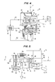
- a second embodiment of the present invention is shown as tracking laser interferometer system 10′.
- This system 10′ is similar to that shown in Figs. 1-5 and discussed above and utilizes many of the same components. These same components are illustrated schematically in Figs. 6 and 7 and are given similar reference numerals with the addition of a prime.
- additional structure is added for the main purpose of eliminating dead path error by eliminating the return of the laser beam from the second steering beam assembly along its initial wave path to the interferometer. Instead, there is one continuous wave path with the receiver of the interferometer being at the end of the overall wave path.
- Dead path error is any change in the laser beam path length between the interferometer beam splitter and the last beam steering optical element of the tracking system. Thus, any change in this path length while the system is tracking introduces such a dead path error.
- prism 170 located above and coupled to upper tubular shaft 64′ and quarter wave plate 172 therebetween.
- a third reflective assembly 174 which is similar to and acts as the first reflective assembly 68 described above except it does not have an additional prism 100 forming a beam splitter.
- this third reflective assembly 174 comprises a quarter wave plate 176, a first prism 178, which is similar to prism 32 discussed above, a second prism 180, which is similar to prism 34 discussed above, and quarter wave plate 184.
- This third reflective assembly 174 is rigidly coupled to the first support 62′ and pivots with it about the Y axis defined by shafts 64′ and 66′.
- the second reflective assembly 186 in this embodiment is different from the second reflective assembly 18 in the embodiment of Figs. 1-5 and comprises as seen in Figs. 6 and 7 a beam splitter 188, four quarter wave plates 190, 192, 194 and 196 affixed to its four sides, and a corner cube retroreflector 198 rigidly coupled to quarter wave plate 194 on the rear of the assembly.
- This second reflective assembly 186 is rigidly coupled to the second support 104′ and pivots with it about the X axis and shafts 106′ and 108′ together with lens 120′ and quad cell 24′.
- the final piece of additional structure in the embodiment of Figs. 6 and 7 is the prism 200 located adjacent the receiver 152′ and aligned with beam guiding prism 160′.
- system 10′ In operation, system 10′ generates a laser beam 14′ from laser 12′ which is intercepted by prism 170 and is redirected 90° substantially coincident with the Y axis and towards the X axis.
- the beam then passes through quarter wave plate 172, tubular shaft 64′, and quarter wave plate 176, at which time it is intercepted by prism 178.
- This prism reflects the laser beam 90° away from the Y axis and parallel to the X axis where it is intercepted by the upper angled surface of second prism 180.
- the laser beam is again reflected 90° in a direction towards the X axis and parallel to the Y axis and it is then reflected again through 90° by the lower angled surface of prism 180 in a direction substantially coincident with the X axis and towards the beam splitter 188.
- a portion of the laser beam, as seen in Fig. 7, is then reflected by the beam splitter 188 at point A′ in a rearward direction away from the X axis and along the R axis where it passes through quarter wave plate 194 and is intercepted by corner cube retroreflector 198.
- This portion of the beam is then reflected back through the quarter wave plate 194, beam splitter 188 and quarter wave plate 190 along the R axis and is intercepted by the retroreflector 20′.
- the retroreflector then reflects the laser beam back through the beam splitter 188 where it is reflected generally along and substantially parallel or coincident with the X axis through quarter wave plates 192 and 102′, a beam splitter formed by prisms 34′ and 100′ and through lens 120′ into the quad cell 24′, which generates an error signal if the beam is laterally displaced from the X axis.
- This error signal is conducted via line 122′ to the control system 42′ where motors 26′ and 28′ are actuated as necessary to pivot the first, second, and third beam steering assemblies 68′, 174 and 186 to reduce the error signal to zero.
- the other portion of the laser beam not reflected into corner cube retroreflector 198 has continued through beam splitter 188, quarter wave plate 192 and through quarter wave plate 102′, where at least a portion of it is reflected downwardly via the upper angled surface of prism 34′ in a direction substantially parallel to the Y axis and away from the X axis.
- This portion of the laser beam is then reflected through 90° via the lower angled surface of prism 34′, reflected again through 90° via prism 32′, and extends downwardly generally along the Y axis through quarter wave plate 96′, tubular shaft 66′, quarter wave plate 162′ and is intercepted by guiding prism 160′.
- This prism reflects this portion of the laser beam towards the prism 200 which finally reflects that portion of the beam into the receiver 152′.
- beam splitter 188 divides the initial laser beam into two portions, one which extends to and is returned from the retroreflector 20′, and another which continues on to the receiver 152′, these two portions of the laser beam can be measured by the receiver to determine the distance of the retroreflector from the reference location.
- the photodetectors 24 and 24′ need not be located as shown in Figs. 1-5 and Figs. 6 and 7. Instead, in both embodiments a photodetector can be located along the beam path behind and rigidly coupled to the retroreflector or behind and rigidly coupled to prism 36 or beam splitter 188. If the photodetector is positioned in these alternative locations, the corresponding optical element would be constructed so as to pass a portion of the laser beam therethrough to the photodetector.
Landscapes
- Engineering & Computer Science (AREA)
- Physics & Mathematics (AREA)
- General Physics & Mathematics (AREA)
- Computer Networks & Wireless Communication (AREA)
- Radar, Positioning & Navigation (AREA)
- Remote Sensing (AREA)
- Electromagnetism (AREA)
- Optical Radar Systems And Details Thereof (AREA)
- Length Measuring Devices By Optical Means (AREA)
- Instruments For Measurement Of Length By Optical Means (AREA)
Applications Claiming Priority (2)
| Application Number | Priority Date | Filing Date | Title |
|---|---|---|---|
| US07/103,116 US4790651A (en) | 1987-09-30 | 1987-09-30 | Tracking laser interferometer |
| US103116 | 1987-09-30 |
Publications (2)
| Publication Number | Publication Date |
|---|---|
| EP0310235A2 true EP0310235A2 (de) | 1989-04-05 |
| EP0310235A3 EP0310235A3 (de) | 1991-02-06 |
Family
ID=22293490
Family Applications (1)
| Application Number | Title | Priority Date | Filing Date |
|---|---|---|---|
| EP19880307555 Withdrawn EP0310235A3 (de) | 1987-09-30 | 1988-08-15 | Einrichtung zum Nachführen eines Laserstrahl-Interferometers |
Country Status (2)
| Country | Link |
|---|---|
| US (1) | US4790651A (de) |
| EP (1) | EP0310235A3 (de) |
Cited By (7)
| Publication number | Priority date | Publication date | Assignee | Title |
|---|---|---|---|---|
| EP0644498A3 (de) * | 1993-09-21 | 1996-04-03 | Westinghouse Electric Corp | Verfahren und System zur Bestimmung der Stellen zum Komponent-Ersatz beim Schweissen. |
| WO1997023787A1 (en) * | 1995-09-01 | 1997-07-03 | Research Corporation Technologies, Inc. | Optical coordinate measuring machine |
| RU2163024C2 (ru) * | 1999-04-19 | 2001-02-10 | Амиров Саид Джапарович | Система для подсвета объекта |
| RU2197002C2 (ru) * | 2000-11-20 | 2003-01-20 | Государственное унитарное предприятие "Конструкторское бюро приборостроения" | Система сопровождения |
| JP2003527564A (ja) * | 1999-05-05 | 2003-09-16 | ザイゴ コーポレーション | 角度および距離を測定するための動的ビーム・ステアリング・アセンブリを有する干渉計システム |
| EP1135668A4 (de) * | 1998-09-18 | 2006-06-14 | Zygo Corp | Interferometer mit dynamischer strahlsteuerung |
| US7903245B2 (en) | 2007-08-20 | 2011-03-08 | Marc Miousset | Multi-beam optical probe and system for dimensional measurement |
Families Citing this family (137)
| Publication number | Priority date | Publication date | Assignee | Title |
|---|---|---|---|---|
| LU87003A1 (fr) * | 1987-09-29 | 1989-04-06 | Europ Communities | Systeme de poursuite d'une cible |
| WO1989012836A1 (fr) * | 1988-06-15 | 1989-12-28 | Japan Industrial Land Development Co., Ltd. | Un dispositif de releve du type a poursuite automatique |
| IL88243A0 (en) * | 1988-10-31 | 1990-07-12 | Israel Aircraft Ind Ltd | Corner cube assembly |
| FR2641872B1 (fr) * | 1989-01-18 | 1991-10-11 | Clausin Jacques | Systeme de localisation d'helicopteres dissimules derriere un ecran vegetal |
| US5113065A (en) * | 1990-09-10 | 1992-05-12 | United Technologies Corporation | Heterodyne circular photodetector array in a tracking system |
| FR2667810B1 (fr) * | 1990-10-10 | 1995-02-17 | Framatome Sa | Procede et dispositif de travail au laser avec controle a distance. |
| IL99346A (en) * | 1991-08-30 | 1996-05-14 | Israel Aircraft Ind Ltd | Boresight system and calibration method |
| WO1993008449A1 (en) * | 1991-10-12 | 1993-04-29 | Renishaw Transducer Systems Limited | Measuring the accuracy of multi-axis machines |
| US5305091A (en) * | 1992-12-07 | 1994-04-19 | Oreo Products Inc. | Optical coordinate measuring system for large objects |
| IL107707A (en) * | 1993-11-22 | 1997-01-10 | Israel State | Means for upgrading existing missile control systems |
| US5532816A (en) * | 1994-03-15 | 1996-07-02 | Stellar Industries, Inc. | Laser tracking wheel alignment measurement apparatus and method |
| US5530549A (en) * | 1994-05-24 | 1996-06-25 | Spatialmetrix Corp. | Probing retroreflector and methods of measuring surfaces therewith |
| US5900938A (en) * | 1996-11-08 | 1999-05-04 | The Research Foundation Of State University Of New York | Laser measurement system for rapid calibration of machine tools |
| US20030145353A1 (en) * | 1997-05-07 | 2003-07-31 | Lightner Jonathan E. | Starch biosynthetic enzymes |
| US5861956A (en) * | 1997-05-27 | 1999-01-19 | Spatialmetrix Corporation | Retroreflector for use with tooling ball |
| US7139080B2 (en) * | 1998-09-18 | 2006-11-21 | Zygo Corporation | Interferometry systems involving a dynamic beam-steering assembly |
| US6252667B1 (en) * | 1998-09-18 | 2001-06-26 | Zygo Corporation | Interferometer having a dynamic beam steering assembly |
| US7800758B1 (en) | 1999-07-23 | 2010-09-21 | Faro Laser Trackers, Llc | Laser-based coordinate measuring device and laser-based method for measuring coordinates |
| US6512588B1 (en) | 1999-05-05 | 2003-01-28 | Zygo Corporation | Method and system for correcting an interferometric angle measurement for the effects of dispersion |
| US6888638B1 (en) | 1999-05-05 | 2005-05-03 | Zygo Corporation | Interferometry system having a dynamic beam steering assembly for measuring angle and distance |
| US6547397B1 (en) | 2000-04-19 | 2003-04-15 | Laser Projection Technologies, Inc. | Apparatus and method for projecting a 3D image |
| US6541759B1 (en) | 2000-06-20 | 2003-04-01 | Zygo Corporation | Interferometry system having a dynamic beam-steering assembly for measuring angle and distance and employing optical fibers for remote photoelectric detection |
| US6563569B2 (en) * | 2000-09-25 | 2003-05-13 | Agency Of Industrial Science & Technology, Ministry Of International Trade & Industry | Laser tracking interferometric length measuring instrument and method of measuring length and coordinates using the same |
| US6480271B1 (en) | 2001-01-08 | 2002-11-12 | The Boeing Company | Traversing laser locating system |
| US6570646B2 (en) | 2001-03-06 | 2003-05-27 | The Regents Of The University Of California | Optical distance measurement device and method thereof |
| US6847452B2 (en) * | 2001-08-02 | 2005-01-25 | Zygo Corporation | Passive zero shear interferometers |
| EP1419361A1 (de) * | 2001-08-23 | 2004-05-19 | Zygo Corporation | Dynamische interferometrische steuerung der richtung eines eingangsstrahls |
| US6912054B2 (en) * | 2001-08-28 | 2005-06-28 | Zygo Corporation | Interferometric stage system |
| JP2003149338A (ja) * | 2001-11-09 | 2003-05-21 | Denso Corp | 物体認識装置及び距離測定装置 |
| ATE519092T1 (de) | 2002-01-16 | 2011-08-15 | Faro Tech Inc | Lasergestützte koordinatenmessapparatur und lasergestütztes koordinatenmessverfahren |
| WO2003069286A2 (en) * | 2002-02-12 | 2003-08-21 | Zygo Corporation | Method and apparatus to measure fiber optic pickup errors in interferometry systems |
| US6856402B2 (en) * | 2002-02-12 | 2005-02-15 | Zygo Corporation | Interferometer with dynamic beam steering element |
| US6906784B2 (en) * | 2002-03-04 | 2005-06-14 | Zygo Corporation | Spatial filtering in interferometry |
| AU2003234413A1 (en) * | 2002-05-13 | 2003-11-11 | Zygo Corporation | Compensation for geometric effects of beam misalignments in plane mirror interferometers |
| US7262860B2 (en) * | 2002-07-29 | 2007-08-28 | Zygo Corporation | Compensation for errors in off-axis interferometric measurements |
| US7274462B2 (en) * | 2002-09-09 | 2007-09-25 | Zygo Corporation | In SITU measurement and compensation of errors due to imperfections in interferometer optics in displacement measuring interferometry systems |
| US7321432B2 (en) * | 2002-09-09 | 2008-01-22 | Zygo Corporation | Measurement and compensation of errors in interferometers |
| EP1583934A1 (de) * | 2002-12-12 | 2005-10-12 | Zygo Corporation | Korrektur von spiegel deformationen während einer photolithographischen belichtung |
| US7327465B2 (en) * | 2003-06-19 | 2008-02-05 | Zygo Corporation | Compensation for effects of beam misalignments in interferometer metrology systems |
| US7286240B2 (en) * | 2003-06-19 | 2007-10-23 | Zygo Corporation | Compensation for geometric effects of beam misalignments in plane mirror interferometer metrology systems |
| US7180603B2 (en) * | 2003-06-26 | 2007-02-20 | Zygo Corporation | Reduction of thermal non-cyclic error effects in interferometers |
| JP2007504459A (ja) | 2003-09-05 | 2007-03-01 | ファロ テクノロジーズ インコーポレーテッド | 自己補償レーザトラッカ |
| US7289226B2 (en) * | 2003-11-04 | 2007-10-30 | Zygo Corporation | Characterization and compensation of errors in multi-axis interferometry systems |
| WO2005067815A1 (en) | 2004-01-05 | 2005-07-28 | Zygo Corporation | Stage alignment in lithography tools |
| US7283248B2 (en) * | 2004-01-06 | 2007-10-16 | Zygo Corporation | Multi-axis interferometers and methods and systems using multi-axis interferometers |
| US7101053B2 (en) * | 2004-01-15 | 2006-09-05 | Associated Universities, Inc. | Multidirectional retroreflectors |
| US7310152B2 (en) * | 2004-03-03 | 2007-12-18 | Zygo Corporation | Interferometer assemblies having reduced cyclic errors and system using the interferometer assemblies |
| US7375823B2 (en) * | 2004-04-22 | 2008-05-20 | Zygo Corporation | Interferometry systems and methods of using interferometry systems |
| JP2007534941A (ja) * | 2004-04-22 | 2007-11-29 | ザイゴ コーポレーション | 光学干渉計システムおよび光学干渉計システムを用いる方法 |
| WO2006014406A2 (en) | 2004-06-30 | 2006-02-09 | Zygo Corporation | Interferometric optical assemblies and systems including interferometric optical assemblies |
| EP1794620B1 (de) * | 2004-09-30 | 2014-01-01 | Faro Technologies Inc. | Absolutentfernungsmessvorrichtung zur messung eines bewegten rückstrahlers |
| US7489407B2 (en) * | 2004-10-06 | 2009-02-10 | Zygo Corporation | Error correction in interferometry systems |
| US7433049B2 (en) * | 2005-03-18 | 2008-10-07 | Zygo Corporation | Multi-axis interferometer with procedure and data processing for mirror mapping |
| JP2008547026A (ja) | 2005-06-23 | 2008-12-25 | ファロ テクノロジーズ インコーポレーテッド | 有関節座標計測機再配置装置及び方法 |
| US7222431B1 (en) | 2006-02-03 | 2007-05-29 | Gilson, Inc. | Alignment correction system and methods of use thereof |
| WO2007124010A2 (en) * | 2006-04-20 | 2007-11-01 | Faro Technologies, Inc. | Camera based six degree-of-freedom target measuring and target tracking device |
| EP2010941B1 (de) * | 2006-04-21 | 2010-11-24 | Faro Technologies Inc. | Kamerabasierte vorrichtung zur zielmessung und zielverfolgung mit sechs freiheitsgraden und drehbarem spiegel |
| JP2007309677A (ja) * | 2006-05-16 | 2007-11-29 | Mitsutoyo Corp | 追尾式レーザ干渉計の絶対距離推定方法及び追尾式レーザ干渉計 |
| DE102006034270A1 (de) * | 2006-07-18 | 2008-01-24 | C. & E. Fein Gmbh | Ortungssystem zur Ortung der Position eines Werkzeugs |
| US7619720B1 (en) * | 2007-12-04 | 2009-11-17 | Itt Manufacturing Enterprises, Inc. | Sequentially addressable radius measurements of an optical surface using a range finder |
| US8467072B2 (en) | 2011-02-14 | 2013-06-18 | Faro Technologies, Inc. | Target apparatus and method of making a measurement with the target apparatus |
| DE112009005524B3 (de) * | 2008-11-17 | 2018-01-25 | Faro Technologies, Inc. | Vorrichtung und Verfahren zum Messen von sechs Freiheitsgraden |
| US9482755B2 (en) | 2008-11-17 | 2016-11-01 | Faro Technologies, Inc. | Measurement system having air temperature compensation between a target and a laser tracker |
| US9354043B2 (en) | 2008-12-04 | 2016-05-31 | Laura P. Solliday | Methods for measuring and modeling the structural health of pressure vessels based on electronic distance measurements |
| US10203268B2 (en) | 2008-12-04 | 2019-02-12 | Laura P. Solliday | Methods for measuring and modeling the process of prestressing concrete during tensioning/detensioning based on electronic distance measurements |
| JP5702524B2 (ja) * | 2009-02-17 | 2015-04-15 | 株式会社ミツトヨ | 追尾式レーザ干渉計 |
| US9551575B2 (en) | 2009-03-25 | 2017-01-24 | Faro Technologies, Inc. | Laser scanner having a multi-color light source and real-time color receiver |
| DE102009015920B4 (de) | 2009-03-25 | 2014-11-20 | Faro Technologies, Inc. | Vorrichtung zum optischen Abtasten und Vermessen einer Umgebung |
| US8659749B2 (en) * | 2009-08-07 | 2014-02-25 | Faro Technologies, Inc. | Absolute distance meter with optical switch |
| US20110069322A1 (en) | 2009-09-21 | 2011-03-24 | Faro Technologies, Inc. | Laser pointing mechanism |
| DE102009057101A1 (de) | 2009-11-20 | 2011-05-26 | Faro Technologies, Inc., Lake Mary | Vorrichtung zum optischen Abtasten und Vermessen einer Umgebung |
| US9210288B2 (en) | 2009-11-20 | 2015-12-08 | Faro Technologies, Inc. | Three-dimensional scanner with dichroic beam splitters to capture a variety of signals |
| US9529083B2 (en) | 2009-11-20 | 2016-12-27 | Faro Technologies, Inc. | Three-dimensional scanner with enhanced spectroscopic energy detector |
| US9113023B2 (en) | 2009-11-20 | 2015-08-18 | Faro Technologies, Inc. | Three-dimensional scanner with spectroscopic energy detector |
| US8630314B2 (en) | 2010-01-11 | 2014-01-14 | Faro Technologies, Inc. | Method and apparatus for synchronizing measurements taken by multiple metrology devices |
| US8832954B2 (en) | 2010-01-20 | 2014-09-16 | Faro Technologies, Inc. | Coordinate measurement machines with removable accessories |
| US9607239B2 (en) | 2010-01-20 | 2017-03-28 | Faro Technologies, Inc. | Articulated arm coordinate measurement machine having a 2D camera and method of obtaining 3D representations |
| US9628775B2 (en) | 2010-01-20 | 2017-04-18 | Faro Technologies, Inc. | Articulated arm coordinate measurement machine having a 2D camera and method of obtaining 3D representations |
| US9163922B2 (en) | 2010-01-20 | 2015-10-20 | Faro Technologies, Inc. | Coordinate measurement machine with distance meter and camera to determine dimensions within camera images |
| US8875409B2 (en) | 2010-01-20 | 2014-11-04 | Faro Technologies, Inc. | Coordinate measurement machines with removable accessories |
| US8898919B2 (en) | 2010-01-20 | 2014-12-02 | Faro Technologies, Inc. | Coordinate measurement machine with distance meter used to establish frame of reference |
| US8615893B2 (en) | 2010-01-20 | 2013-12-31 | Faro Technologies, Inc. | Portable articulated arm coordinate measuring machine having integrated software controls |
| DE112011100292B4 (de) * | 2010-01-20 | 2016-11-24 | Faro Technologies Inc. | Anzeige für ein Koordinatenmessgerät |
| US8677643B2 (en) | 2010-01-20 | 2014-03-25 | Faro Technologies, Inc. | Coordinate measurement machines with removable accessories |
| WO2011090888A2 (en) * | 2010-01-20 | 2011-07-28 | Faro Technologies, Inc. | Coordinate measuring machine having an illuminated probe end and method of operation |
| DE112011100294B4 (de) * | 2010-01-20 | 2019-06-13 | Faro Technologies Inc. | Tragbares Gelenkarm-Koordinatenmessgerät mit einer Multibus-Armtechnologie |
| US9879976B2 (en) | 2010-01-20 | 2018-01-30 | Faro Technologies, Inc. | Articulated arm coordinate measurement machine that uses a 2D camera to determine 3D coordinates of smoothly continuous edge features |
| US8724119B2 (en) | 2010-04-21 | 2014-05-13 | Faro Technologies, Inc. | Method for using a handheld appliance to select, lock onto, and track a retroreflector with a laser tracker |
| US8422034B2 (en) | 2010-04-21 | 2013-04-16 | Faro Technologies, Inc. | Method and apparatus for using gestures to control a laser tracker |
| US8537371B2 (en) | 2010-04-21 | 2013-09-17 | Faro Technologies, Inc. | Method and apparatus for using gestures to control a laser tracker |
| US9400170B2 (en) | 2010-04-21 | 2016-07-26 | Faro Technologies, Inc. | Automatic measurement of dimensional data within an acceptance region by a laser tracker |
| US9377885B2 (en) | 2010-04-21 | 2016-06-28 | Faro Technologies, Inc. | Method and apparatus for locking onto a retroreflector with a laser tracker |
| US8619265B2 (en) | 2011-03-14 | 2013-12-31 | Faro Technologies, Inc. | Automatic measurement of dimensional data with a laser tracker |
| US9772394B2 (en) | 2010-04-21 | 2017-09-26 | Faro Technologies, Inc. | Method and apparatus for following an operator and locking onto a retroreflector with a laser tracker |
| DE102010020925B4 (de) | 2010-05-10 | 2014-02-27 | Faro Technologies, Inc. | Verfahren zum optischen Abtasten und Vermessen einer Umgebung |
| CN103003713B (zh) | 2010-09-08 | 2015-04-01 | 法罗技术股份有限公司 | 具有投影器的激光扫描器或激光跟踪器 |
| US8659752B2 (en) | 2010-10-25 | 2014-02-25 | Faro Technologies, Inc. | Automated warm-up and stability check for laser trackers |
| US9168654B2 (en) | 2010-11-16 | 2015-10-27 | Faro Technologies, Inc. | Coordinate measuring machines with dual layer arm |
| US8902408B2 (en) | 2011-02-14 | 2014-12-02 | Faro Technologies Inc. | Laser tracker used with six degree-of-freedom probe having separable spherical retroreflector |
| USD688577S1 (en) | 2012-02-21 | 2013-08-27 | Faro Technologies, Inc. | Laser tracker |
| US8537376B2 (en) | 2011-04-15 | 2013-09-17 | Faro Technologies, Inc. | Enhanced position detector in laser tracker |
| US9164173B2 (en) | 2011-04-15 | 2015-10-20 | Faro Technologies, Inc. | Laser tracker that uses a fiber-optic coupler and an achromatic launch to align and collimate two wavelengths of light |
| US9686532B2 (en) | 2011-04-15 | 2017-06-20 | Faro Technologies, Inc. | System and method of acquiring three-dimensional coordinates using multiple coordinate measurement devices |
| US9482529B2 (en) | 2011-04-15 | 2016-11-01 | Faro Technologies, Inc. | Three-dimensional coordinate scanner and method of operation |
| CN103620440A (zh) | 2011-06-14 | 2014-03-05 | 法罗技术股份有限公司 | 用于激光跟踪器的自动和加速加热和稳定性检验 |
| US9067690B2 (en) * | 2011-08-23 | 2015-06-30 | The Boeing Company | Cataloging system for recording manufacture anomaly data related to type, severity, and position with a wireless probe |
| DE102012100609A1 (de) | 2012-01-25 | 2013-07-25 | Faro Technologies, Inc. | Vorrichtung zum optischen Abtasten und Vermessen einer Umgebung |
| JP6099675B2 (ja) | 2012-01-27 | 2017-03-22 | ファロ テクノロジーズ インコーポレーテッド | バーコード識別による検査方法 |
| US8997362B2 (en) | 2012-07-17 | 2015-04-07 | Faro Technologies, Inc. | Portable articulated arm coordinate measuring machine with optical communications bus |
| US10067231B2 (en) | 2012-10-05 | 2018-09-04 | Faro Technologies, Inc. | Registration calculation of three-dimensional scanner data performed between scans based on measurements by two-dimensional scanner |
| US9513107B2 (en) | 2012-10-05 | 2016-12-06 | Faro Technologies, Inc. | Registration calculation between three-dimensional (3D) scans based on two-dimensional (2D) scan data from a 3D scanner |
| DE102012109481A1 (de) | 2012-10-05 | 2014-04-10 | Faro Technologies, Inc. | Vorrichtung zum optischen Abtasten und Vermessen einer Umgebung |
| EP2746807A1 (de) | 2012-12-20 | 2014-06-25 | Leica Geosystems AG | Selbstkalibrierender Lasertracker und Selbstkalibrierungsverfahren |
| EP2746806B1 (de) | 2012-12-21 | 2016-10-19 | Leica Geosystems AG | Selbstkalibrierender Lasertracker und Selbstkalibrierungsverfahren |
| US9041914B2 (en) | 2013-03-15 | 2015-05-26 | Faro Technologies, Inc. | Three-dimensional coordinate scanner and method of operation |
| US9234742B2 (en) | 2013-05-01 | 2016-01-12 | Faro Technologies, Inc. | Method and apparatus for using gestures to control a laser tracker |
| US9857159B1 (en) | 2013-09-24 | 2018-01-02 | TVS Holdings, LLC | Velocity compensated frequency sweeping interferometer and method of using same |
| US9395174B2 (en) | 2014-06-27 | 2016-07-19 | Faro Technologies, Inc. | Determining retroreflector orientation by optimizing spatial fit |
| WO2016073208A1 (en) | 2014-11-03 | 2016-05-12 | Faro Technologies, Inc. | Method and apparatus for locking onto a retroreflector with a laser tracker |
| US9976947B1 (en) | 2014-11-24 | 2018-05-22 | TVS Holdings, LLC | Position measurement device |
| US9983298B2 (en) | 2015-02-05 | 2018-05-29 | Associated Universities, LLC | Fiber optic based laser range finder |
| JP6539485B2 (ja) * | 2015-04-21 | 2019-07-03 | 株式会社ミツトヨ | 追尾式レーザ干渉計を用いた測定システム、及びその復帰方法 |
| DE102015122844A1 (de) | 2015-12-27 | 2017-06-29 | Faro Technologies, Inc. | 3D-Messvorrichtung mit Batteriepack |
| ES2899585T3 (es) | 2016-07-15 | 2022-03-14 | Fastbrick Ip Pty Ltd | Pluma para transporte de material |
| JP7061119B2 (ja) | 2016-07-15 | 2022-04-27 | ファストブリック・アイピー・プロプライエタリー・リミテッド | 車両に組み込まれた煉瓦/ブロック敷設機 |
| US20180088202A1 (en) | 2016-09-23 | 2018-03-29 | Faro Technologies, Inc. | Apparatus and method for relocating an articulating-arm coordinate measuring machine |
| CN111095355B (zh) | 2017-07-05 | 2023-10-20 | 快砖知识产权私人有限公司 | 实时定位和定向跟踪器 |
| AU2018317941B2 (en) | 2017-08-17 | 2023-11-09 | Fastbrick Ip Pty Ltd | Laser tracker with improved roll angle measurement |
| US11958193B2 (en) | 2017-08-17 | 2024-04-16 | Fastbrick Ip Pty Ltd | Communication system for an interaction system |
| CN111212799B (zh) | 2017-10-11 | 2023-04-14 | 快砖知识产权私人有限公司 | 用于传送物体的机器以及与其一起使用的多隔间转盘 |
| US12311546B2 (en) | 2018-07-16 | 2025-05-27 | Fastbrick Ip Pty Ltd | Active damping system |
| WO2020014737A1 (en) | 2018-07-16 | 2020-01-23 | Fastbrick Ip Pty Ltd | Backup tracking for an interaction system |
| US12123983B2 (en) | 2019-04-24 | 2024-10-22 | The Boeing Company | Aligning sensors on vehicles using sensor output |
| US11639234B2 (en) | 2019-04-24 | 2023-05-02 | The Boeing Company | Method, system and apparatus for aligning a removable sensor on a vehicle |
| CA3076342A1 (en) * | 2019-04-24 | 2020-10-24 | The Boeing Company | Aligning sensors on vehicles using sensor output |
| CN115443363A (zh) | 2020-04-22 | 2022-12-06 | 快砖知识产权私人有限公司 | 块传送装置及用于与其一起使用的改进的夹紧组件 |
| AU2021304545B2 (en) | 2020-07-08 | 2025-12-04 | Fastbrick Ip Pty Ltd | Adhesive application system |
Family Cites Families (6)
| Publication number | Priority date | Publication date | Assignee | Title |
|---|---|---|---|---|
| US4457625A (en) * | 1981-07-13 | 1984-07-03 | Itek Corporation | Self calibrating contour measuring system using fringe counting interferometers |
| US4436417A (en) * | 1982-04-14 | 1984-03-13 | Itek Corporation | Beam director for optical ranging system |
| DE3334460A1 (de) * | 1983-09-23 | 1985-04-11 | Fa. Carl Zeiss, 7920 Heidenheim | Mehrkoordinaten-messmaschine |
| JPS60237307A (ja) * | 1984-05-11 | 1985-11-26 | Yokogawa Hewlett Packard Ltd | レ−ザ測長器 |
| US4621926A (en) * | 1985-04-30 | 1986-11-11 | Lasercon Corporation | Interferometer system for controlling non-rectilinear movement of an object |
| US4714339B2 (en) * | 1986-02-28 | 2000-05-23 | Us Commerce | Three and five axis laser tracking systems |
-
1987
- 1987-09-30 US US07/103,116 patent/US4790651A/en not_active Expired - Lifetime
-
1988
- 1988-08-15 EP EP19880307555 patent/EP0310235A3/de not_active Withdrawn
Cited By (9)
| Publication number | Priority date | Publication date | Assignee | Title |
|---|---|---|---|---|
| EP0644498A3 (de) * | 1993-09-21 | 1996-04-03 | Westinghouse Electric Corp | Verfahren und System zur Bestimmung der Stellen zum Komponent-Ersatz beim Schweissen. |
| WO1997023787A1 (en) * | 1995-09-01 | 1997-07-03 | Research Corporation Technologies, Inc. | Optical coordinate measuring machine |
| US5920394A (en) * | 1995-09-01 | 1999-07-06 | Research Corporation Technologies, Inc. | Optical coordinate measuring machine |
| EP1135668A4 (de) * | 1998-09-18 | 2006-06-14 | Zygo Corp | Interferometer mit dynamischer strahlsteuerung |
| RU2163024C2 (ru) * | 1999-04-19 | 2001-02-10 | Амиров Саид Джапарович | Система для подсвета объекта |
| JP2003527564A (ja) * | 1999-05-05 | 2003-09-16 | ザイゴ コーポレーション | 角度および距離を測定するための動的ビーム・ステアリング・アセンブリを有する干渉計システム |
| EP1454112A4 (de) * | 1999-05-05 | 2006-09-20 | Zygo Corp | Interferometrisches system mit einer dynamischen lichtstrahlsteuervorrichtung für das messen von winkeln und distanzen |
| RU2197002C2 (ru) * | 2000-11-20 | 2003-01-20 | Государственное унитарное предприятие "Конструкторское бюро приборостроения" | Система сопровождения |
| US7903245B2 (en) | 2007-08-20 | 2011-03-08 | Marc Miousset | Multi-beam optical probe and system for dimensional measurement |
Also Published As
| Publication number | Publication date |
|---|---|
| EP0310235A3 (de) | 1991-02-06 |
| US4790651A (en) | 1988-12-13 |
Similar Documents
| Publication | Publication Date | Title |
|---|---|---|
| US4790651A (en) | Tracking laser interferometer | |
| US4691446A (en) | Three-dimensional position measuring apparatus | |
| US6147748A (en) | Tracking system | |
| US5530549A (en) | Probing retroreflector and methods of measuring surfaces therewith | |
| US9989350B2 (en) | Laser-based coordinate measuring device and laser-based method for measuring coordinates | |
| EP0374265B1 (de) | Vermessungsgerät mit automatischer verfolgung | |
| EP0160999B1 (de) | Lagemessanordnung | |
| EP1466136B1 (de) | Lasergestützte koordinatenmessapparatur und lasergestütztes koordinatenmessverfahren | |
| CN106595480B (zh) | 用于测量转轴六自由度几何误差的激光测量系统及方法 | |
| US4866362A (en) | Target tracking system | |
| GB2121166A (en) | Laser alignment | |
| US4117319A (en) | Alignment system for lasers | |
| US5146290A (en) | Process and apparatus for determining the position of an object | |
| US4981353A (en) | Position locating apparatus for an underwater moving body | |
| US4743769A (en) | Non-contacting measuring apparatus for measuring a displacement in dependence on the incidence of a laser beam on a laser beam detector | |
| CN115307550A (zh) | 可校准跟踪测量参数的相对位移测量跟踪方法与装置 | |
| JPH07120213A (ja) | 追尾式レーザ干渉計 | |
| US5633716A (en) | Self-aligning retroreflector target carrier | |
| JPH02500615A (ja) | 真直度干渉計システムおよび光学部品 | |
| JPH05504833A (ja) | 2軸平面鏡干渉計 | |
| JP2692778B2 (ja) | 高速追尾式レーザ干渉測長器 | |
| CN109759753A (zh) | 激光测距焊缝跟踪器及智能焊接系统 | |
| JPH07117414B2 (ja) | 自動視準式光波距離計 | |
| JP2795612B2 (ja) | 高速追尾式レーザ干渉測長器 | |
| JP2823112B2 (ja) | 測距儀 |
Legal Events
| Date | Code | Title | Description |
|---|---|---|---|
| PUAI | Public reference made under article 153(3) epc to a published international application that has entered the european phase |
Free format text: ORIGINAL CODE: 0009012 |
|
| AK | Designated contracting states |
Kind code of ref document: A2 Designated state(s): CH DE FR GB LI SE |
|
| PUAL | Search report despatched |
Free format text: ORIGINAL CODE: 0009013 |
|
| AK | Designated contracting states |
Kind code of ref document: A3 Designated state(s): CH DE FR GB LI SE |
|
| 17P | Request for examination filed |
Effective date: 19910805 |
|
| 17Q | First examination report despatched |
Effective date: 19921022 |
|
| STAA | Information on the status of an ep patent application or granted ep patent |
Free format text: STATUS: THE APPLICATION IS DEEMED TO BE WITHDRAWN |
|
| 18D | Application deemed to be withdrawn |
Effective date: 19930504 |