EP0310426A2 - Turbolader mit elektrischer Drehmaschine - Google Patents
Turbolader mit elektrischer Drehmaschine Download PDFInfo
- Publication number
- EP0310426A2 EP0310426A2 EP88309114A EP88309114A EP0310426A2 EP 0310426 A2 EP0310426 A2 EP 0310426A2 EP 88309114 A EP88309114 A EP 88309114A EP 88309114 A EP88309114 A EP 88309114A EP 0310426 A2 EP0310426 A2 EP 0310426A2
- Authority
- EP
- European Patent Office
- Prior art keywords
- turbocharger
- electric machine
- rotary electric
- machine according
- detecting
- Prior art date
- Legal status (The legal status is an assumption and is not a legal conclusion. Google has not performed a legal analysis and makes no representation as to the accuracy of the status listed.)
- Granted
Links
Images

Classifications
-
- F—MECHANICAL ENGINEERING; LIGHTING; HEATING; WEAPONS; BLASTING
- F02—COMBUSTION ENGINES; HOT-GAS OR COMBUSTION-PRODUCT ENGINE PLANTS
- F02B—INTERNAL-COMBUSTION PISTON ENGINES; COMBUSTION ENGINES IN GENERAL
- F02B37/00—Engines characterised by provision of pumps driven at least for part of the time by exhaust
- F02B37/04—Engines with exhaust drive and other drive of pumps, e.g. with exhaust-driven pump and mechanically-driven second pump
- F02B37/10—Engines with exhaust drive and other drive of pumps, e.g. with exhaust-driven pump and mechanically-driven second pump at least one pump being alternatively or simultaneously driven by exhaust and other drive, e.g. by pressurised fluid from a reservoir or an engine-driven pump
-
- F—MECHANICAL ENGINEERING; LIGHTING; HEATING; WEAPONS; BLASTING
- F01—MACHINES OR ENGINES IN GENERAL; ENGINE PLANTS IN GENERAL; STEAM ENGINES
- F01D—NON-POSITIVE DISPLACEMENT MACHINES OR ENGINES, e.g. STEAM TURBINES
- F01D15/00—Adaptations of machines or engines for special use; Combinations of engines with devices driven thereby
- F01D15/10—Adaptations for driving, or combinations with, electric generators
-
- H—ELECTRICITY
- H02—GENERATION; CONVERSION OR DISTRIBUTION OF ELECTRIC POWER
- H02K—DYNAMO-ELECTRIC MACHINES
- H02K11/00—Structural association of dynamo-electric machines with electric components or with devices for shielding, monitoring or protection
- H02K11/01—Structural association of dynamo-electric machines with electric components or with devices for shielding, monitoring or protection for shielding from electromagnetic fields, i.e. structural association with shields
- H02K11/014—Shields associated with stationary parts, e.g. stator cores
- H02K11/0141—Shields associated with casings, enclosures or brackets
-
- H—ELECTRICITY
- H02—GENERATION; CONVERSION OR DISTRIBUTION OF ELECTRIC POWER
- H02K—DYNAMO-ELECTRIC MACHINES
- H02K29/00—Motors or generators having non-mechanical commutating devices, e.g. discharge tubes or semiconductor devices
- H02K29/06—Motors or generators having non-mechanical commutating devices, e.g. discharge tubes or semiconductor devices with position sensing devices
- H02K29/10—Motors or generators having non-mechanical commutating devices, e.g. discharge tubes or semiconductor devices with position sensing devices using light effect devices
-
- H—ELECTRICITY
- H02—GENERATION; CONVERSION OR DISTRIBUTION OF ELECTRIC POWER
- H02K—DYNAMO-ELECTRIC MACHINES
- H02K29/00—Motors or generators having non-mechanical commutating devices, e.g. discharge tubes or semiconductor devices
- H02K29/06—Motors or generators having non-mechanical commutating devices, e.g. discharge tubes or semiconductor devices with position sensing devices
- H02K29/12—Motors or generators having non-mechanical commutating devices, e.g. discharge tubes or semiconductor devices with position sensing devices using detecting coils using the machine windings as detecting coil
-
- H—ELECTRICITY
- H02—GENERATION; CONVERSION OR DISTRIBUTION OF ELECTRIC POWER
- H02K—DYNAMO-ELECTRIC MACHINES
- H02K7/00—Arrangements for handling mechanical energy structurally associated with dynamo-electric machines, e.g. structural association with mechanical driving motors or auxiliary dynamo-electric machines
-
- H—ELECTRICITY
- H02—GENERATION; CONVERSION OR DISTRIBUTION OF ELECTRIC POWER
- H02K—DYNAMO-ELECTRIC MACHINES
- H02K7/00—Arrangements for handling mechanical energy structurally associated with dynamo-electric machines, e.g. structural association with mechanical driving motors or auxiliary dynamo-electric machines
- H02K7/14—Structural association with mechanical loads, e.g. with hand-held machine tools or fans
-
- Y—GENERAL TAGGING OF NEW TECHNOLOGICAL DEVELOPMENTS; GENERAL TAGGING OF CROSS-SECTIONAL TECHNOLOGIES SPANNING OVER SEVERAL SECTIONS OF THE IPC; TECHNICAL SUBJECTS COVERED BY FORMER USPC CROSS-REFERENCE ART COLLECTIONS [XRACs] AND DIGESTS
- Y02—TECHNOLOGIES OR APPLICATIONS FOR MITIGATION OR ADAPTATION AGAINST CLIMATE CHANGE
- Y02T—CLIMATE CHANGE MITIGATION TECHNOLOGIES RELATED TO TRANSPORTATION
- Y02T10/00—Road transport of goods or passengers
- Y02T10/10—Internal combustion engine [ICE] based vehicles
- Y02T10/12—Improving ICE efficiencies
Definitions
- the present invention relates to a turbocharger with a rotary electric machine, which can be driven by the energy of exhaust gases discharged from an internal combustion engine.
- Japanese Laid-Open Patent Publication No. 59-101040 discloses an engine supercharging system including a rotary electric machine mounted on the rotatable shaft of a turbocharger combined with an internal combustion engine.
- the rotary electric machine When the internal combustion engine rotates at a low speed, the rotary electric machine operates as an electric motor to increase the boost pressure for increasing the power output from the engine.
- the rotary electric machine When the internal combustion engine rotates at a high speed, the rotary electric machine operates as an electric generator to produce electric power for charging a battery.
- Another turbocharger for an internal combustion engine disclosed in Japanese Laid-Open Patent Publication No. 60-195329 includes a rotary electric machine mounted on the rotatable shaft of the turbocharger, the rotary electric machine being operable as an electric motor or an electric generator dependent on the operating conditions of the internal combustion engine.
- turbochargers disclosed in the above publications do not have any means for detecting the position of magnetic poles of the rotor which has a permanent magnet. Therefore, in the disclosed turbochargers, it is impossible to control the phase of electric power supplied to the stator dependent on the rotation of the rotor, and thus the rotary electric machine cannot efficiently be operated.
- a magnetic sensor or an optical sensor is employed as a device for detecting the angular position of a rotating body.
- a magnetic sensor is used as a means for detecting the position of magnetic poles of a rotor having a permanent magnet in a rotary electric machine, it is difficult for the magnetic sensor to detect the exact angular position of the rotor because of a magnetic field produced by the strong permanent magnet of the rotor or a intensive magnetic field produced by a large current flowing through the coils of the stator when the rotary electric machine is operated as an electric motor.
- An optical sensor employing an optical fiber is advantageous in that it is not adversely affected by any magnetic field, but disadvantageous in that it is susceptible to oil and dust, and its output signal is greatly lowered in level during operation over a long period of time, thus failing to detect the exact angular position of the rotor.
- Another object of the present invention is to provide a turbocharger with a rotary electric machine, which has a position detecting means for accurately detecting the angular position of magnetic poles of a rotor without being affected by oil and dust.
- a turbocharger with a rotary electric machine including a turbine impeller drivable by the energy of exhaust gases emitted from an internal combustion engine, a rotatable shaft having one end coupled to the turbine impeller, a compressor impeller mounted on the other end of the rotatable shaft, a magnet rotor mounted on the rotatable shaft and having a permanent magnet, and a stator core disposed around the magnet core
- the turbocharger comprising: detectable means mounted on a rotatable member of the turbocharger and disposed in a position corresponding to the angular position of a magnetic pole of the magnet rotor; detecting means disposed in a position coacting with the detectable means for detecting the angular position of the detectable means upon rotation thereof; and shield means for protecting detecting operation of the detecting means to shield the detecting means from influences coming from other than the detectable means.
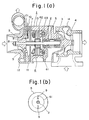
- a turbocharger housing assembly 1 comprises a turbine housing 14, a compressor housing 12, and a central housing 13 disposed therebetween.
- a shaft 2 is rotatably supported in the housing assembly 1 by means of a pair of bearings 3.
- a turbine impeller 4 housed in the turbine housing 14 is mounted on one end of the shaft 2, whereas a compressor impeller 5 housed in the compressor housing 12 is mounted on the other end of the shaft 2.
- a rotary electric machine 6 is disposed on the rotatable shaft 2 in the central housing 13 and comprises a magnet rotor 61 mounted on the shaft 2, a stator core 62 disposed in confronting relation to the magnet rotor 61, and stator coils 63 wound on the stator core 62.
- the magnet rotor 61 is in the form of a cylindrical permanent magnet made of a rare earth element and having intensive residual magnetism.
- an electric current is supplied to the stator coils 63.
- the rotary electric machine 6 operates as an electric generator, electric power induced by the stator coils 63 is extracted.
- a tubular spacer 7 fitted over the shaft 2.
- the spacer 7 keeps the rotor 61 and the compressor impeller 5 spaced a certain distance from each other.
- Permanent magnets 9 for detecting the position of magnetic poles are embedded in the back of the blades of the compressor impeller 5. Where the permanent magnet of the rotor 61 has two N and S poles, these magnets 9 are positioned in radial alignment with the respective N and S poles as shown in Fig. 1(b).
- a magnetic sensor 10 is supported in the central housing 13.
- the magnetic sensor 10 has on its inner tip end a detector coil 101 disposed in a radial position which confronts the permanent magnets 9 embedded in the back of the blades of the compressor impeller 5.
- the magnetic sensor 10 serves to detect the angular position of the magnetic poles of the magnetic rotor 61 rotating with the compressor impeller 5 by detecting a change in the magnetic field produced by movement of the permanent magnets 9 upon rotation of the compressor impeller 5.
- a detected signal is sent from the magnetic sensor 10 to a controller (not shown).
- a shield plate 11 is embedded in the central housing 13 between the magnetic sensor 11 and the magnet rotor 61.
- the shield plate 11 comprises an annular thin steel plate made of a magnetic material such as S10C, S25C, or the like.
- the shield plate 11 serves to absorb changes in the magnetic field due to rotation of the permanent magnet of the rotor 61 or due to changes in an electric current flow ing through the stator coils 63, and to suppress noise which would otherwise be induced in the magnetic sensor 10 by such changes in the magnetic field.
- the turbocharger with the rotary electric machine thus constructed will operate as follows:
- the turbine impeller 4 is driven by the energy of exhaust gases emitted from an internal combustion engine to rotate the compressor impeller 5 which produces and supplies compressed air into the internal combustion engine.
- the compressor impeller 5 is rotated, the permanent magnets 9 embedded in the back of the blades thereof are also rotated.
- a change in the magnetic field from the permanent magnets 9 is detected by the magnetic sensor 10, which then transmits a detected signal to the controller. Since the transmitted signal corresponds to the angular position of the magnetic poles of the magnet rotor 61, the phase or angular position of the magnetic poles of the magnet rotor 61 can accurately be detected.
- the shield plate 11 Since the shield plate 11 is disposed between the magnetic sensor 10 and the magnet rotor 61, the shield plate 11 absorbs changes in the magnetic field due to rotation of the permanent magnet of the rotor 61 or due to changes in an electric current flowing through the stator coils 63 and suppresses noise which would otherwise be induced in the magnetic sensor 10 by such magnetic field changes. Therefore, the detected signal from the magnetic sensor 10 is of a good S/N ratio. Inasmuch as the permanent magnets 9 for detecting the angular position of the magnetic poles are embedded in the back of the blades of the compressor impeller 5, they are not adversely affected by centrifugal forces produced when the compressor impeller 5 rotates at very high speeds, and it is easy to make adjustments for rotational balancing of the compressor impeller 5.
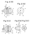
- Figs. 2(a) and 2(b) illustrate a turbocharger according to a second embodiment of the present invention.
- thin amorphous layers 91 of silicon steel are attached to the compressor impeller 5 in place of the permanent magnets 9 in the first embodiment.
- Those parts in Figs. 2(a) and 2(b) which are identical to those of Figs. 1(a) and 1(b) are denoted by identical reference numerals.
- a compressor impeller 5 is made of a nonmagnetic material such as an aluminum alloy, and nonmagnetized thin layers 91 of amorphous silicon steel are firmly deposited by evaporation on the compressor impeller 5 at radial positions corresponding to the N and S poles of the permanent magnet of a rotor 61.
- a magnetic sensor 100 has a magnetic pole and a detector coil for detecting a change in the magnetic field which is caused by a magnetic member approaching the magnetic sensor 100. Upon such detection, the detector coil transmits a signal to a non-illustrated controller.
- the magnetic sensor 100 transmits a detected signal each time one of the thin layers 91 moves past the magnetic sensor 100. Since the transmitted signal corresponds to the angular position of one of the magnetic poles of the rotor 61, the angular position of the magnetic poles of the rotor 61 as it rotates can accurately be detected.
- a shield plate 11 is also provided to protect the magnetic sensor 100 from the magnetic fields from the rotor 61 and the stator coils 63. Therefore, the detected signal from the magnetic sensor 100 is of a good S/N ratio.
- Figs. 3(a), 3(b), and 3(c) illustrate a turbocharger according to a third embodiment of the present invention.
- a detecting permanent magnet is disposed between the compressor impeller and the fastening nut.
- a tubular detecting permanent magnet 92 is mounted on and around a rotatable shaft 2 and fixed to the distal end of a compressor impeller 5 by means of a nut 8.
- a thin nonmagnetic protective ring 93 is forced-fitted over the detecting permanent magnet 92 to prevent the latter from being damaged or broken under centrifugal forces when the turbocharger operates at very high speeds.
- the permanent magnet 92 is magnetized in the same magnetic pole pattern and direction as those of the permanent magnet of the rotor 61 so that the permanent magnet 92 has the same radial distribution of lines of magnetic force as that of the permanent magnet of the rotor 61.
- a magnetic sensor 102 has a detector coil for detecting changes in the magnetic field from the detecting permanent magnet 92 as it rotates. A detected signal from the magnetic sensor 102 is sent to a controller (not shown).
- the magnetic sensor 102 detects a change in the magnetic field from the detecting permanent magnet 92, which corresponds to a change in the magnetic field from the rotor 61 as it rotates. Since a shield plate 11 shields the magnetic sensor 102 from the magnetic fields from the rotor 61 and the stator coils 63, the magnetic sensor 102 can produce a detected signal of a high S/N ratio.
- Figs. 4(a) and 4(b) show a turbocharger according to a fourth embodiment of the present invention.
- a detecting magnetic member with projections is disposed between the compressor impeller and the fastening nut.
- Those parts in Fig. 4(a) which are identical to those of Figs. 2(a) and 2(b) are designated by identical reference numerals.
- a ring-shaped nonmagnetized detecting magnetic member 93 is mounted on a rotatable shaft 2 and fixed to the distal end of a compressor impeller 5 by means of a nut 8.
- the detecting magnetic member 8 has on its outer periphery two diametrically opposite projections 931 projecting radially outwardly and positionally corresponding to the magnetic poles of the permanent magnet of a rotor 61.
- the magnetic sensor 100 detects a change in the magnetic field and transmits a detected signal to detect the angular position of the magnetic poles of the rotor 61.
- the magnetic sensor 100 is shielded by a shield plate 11 from the magnetic fields from the rotor 61 and the stator coils 63.
- Fig. 4(c) shows a detecting magnetic member according to another embodiment, the detecting magnetic member comprising a washered nut 81 made of a nonmagnetized magnetic material and having two radially outward projections.
- Figs. 5(a) and 5(b) show a turbocharger according to a fifth embodiment of the present invention. Those parts in Figs. 5(a) and 5(c) which are identical to those of the previous embodiments are denoted by identical reference numerals.
- a spacer 7 has surfaces of different reflectivities, which can be detected through an optical fiber for detecting rotation of a rotor. More specifically, in Figs. 5(a) and 5(b), a tubular spacer 7 is mounted on a rotatable shaft 2 between a rotor 61 and a compressor impeller 5 and fixedly attached to the rotor 61 and the compressor impeller 5 by means of a nut 8. As shown in Fig.
- the outer periphery of the spacer 7 is coated with a white paint layer 71 and a black paint layer 72, or has a surface plated to provide a smooth surface and another surface etched to provide a nonreflective surface, so that the spacer 7 has surfaces of different light reflectivities.
- the outer peripheral surface of the spacer 7 is thus coated or treated in different areas oriented in the same direction as the magnetizing direction of the permanent magnet of the rotor 61.
- the different reflectivities of the outer periphery of the spacer 7 are detected through an optical fiber 200 which supplies a detected signal to a controller (not shown).
- the rotor 61 and the compressor impeller 5 are separated from the turbine impeller by a partition 301 disposed around the shaft 2 with a seal ring 300 therebetween for preventing the entry of exhaust gases, oil, and the like from the turbine impeller along the shaft 2.
- Figs. 6(a) and 6(b) show a turbocharger according to a sixth embodiment of the present invention.
- Those components in Figs. 6(a) and 6(b) which are identical to those of Figs. 5(a) and 5(b) are denoted by identical reference numerals.
- an axially end side of a rotor 61 is treated to provide different reflectivities in areas oriented in the same direction as the magnetizing direction of the permanent magnet of the rotor 61 itself.
- the angular position of the magnetic poles of the rotor 61 can be detected through an optical fiber 200 based on the different reflectivities on the rotor 61.
Landscapes
- Engineering & Computer Science (AREA)
- Power Engineering (AREA)
- Mechanical Engineering (AREA)
- General Engineering & Computer Science (AREA)
- Chemical & Material Sciences (AREA)
- Combustion & Propulsion (AREA)
- Physics & Mathematics (AREA)
- Electromagnetism (AREA)
- Supercharger (AREA)
Applications Claiming Priority (2)
| Application Number | Priority Date | Filing Date | Title |
|---|---|---|---|
| JP62247587A JPH0192526A (ja) | 1987-09-30 | 1987-09-30 | 回転電機付ターボチャージャ |
| JP247587/87 | 1987-09-30 |
Publications (3)
| Publication Number | Publication Date |
|---|---|
| EP0310426A2 true EP0310426A2 (de) | 1989-04-05 |
| EP0310426A3 EP0310426A3 (en) | 1990-03-21 |
| EP0310426B1 EP0310426B1 (de) | 1992-07-29 |
Family
ID=17165725
Family Applications (1)
| Application Number | Title | Priority Date | Filing Date |
|---|---|---|---|
| EP88309114A Expired - Lifetime EP0310426B1 (de) | 1987-09-30 | 1988-09-30 | Turbolader mit elektrischer Drehmaschine |
Country Status (4)
| Country | Link |
|---|---|
| US (1) | US4924674A (de) |
| EP (1) | EP0310426B1 (de) |
| JP (1) | JPH0192526A (de) |
| DE (1) | DE3873242T2 (de) |
Cited By (16)
| Publication number | Priority date | Publication date | Assignee | Title |
|---|---|---|---|---|
| EP0392677A1 (de) * | 1989-04-13 | 1990-10-17 | Isuzu Motors Limited | Turbolader mit einer Lagerungsvorrichtung für eine Hochgeschwindigkeitswelle |
| EP0420666A1 (de) * | 1989-09-28 | 1991-04-03 | Isuzu Motors Limited | Turbolader mit elektrischer Rotationsmaschine |
| EP0433040A1 (de) * | 1989-12-12 | 1991-06-19 | Isuzu Ceramics Research Institute Co., Ltd. | Maschine mit magnetischem Schwungrad |
| FR2685574A1 (fr) * | 1991-12-20 | 1993-06-25 | Valeo Systemes Dessuyage | Rotor a aimants permanents dote d'une indication de sa position angulaire instantanee et machine magneto-dynamique, comme un moteur sans collecteur, equipee d'un tel rotor. |
| GB2335710A (en) * | 1998-03-27 | 1999-09-29 | Aisin Seiki | Hybrid turbocharger with air bearings |
| WO2005064135A3 (en) * | 2003-12-20 | 2005-09-29 | Honeywell Int Inc | Center housing design for electric assisted turbocharger |
| WO2006005662A1 (de) * | 2004-07-15 | 2006-01-19 | Siemens Aktiengesellschaft | Abgasturbolader |
| WO2006045680A1 (de) * | 2004-10-29 | 2006-05-04 | Siemens Aktiengesellschaft | Abgasturbolader |
| WO2007057257A1 (de) * | 2005-11-15 | 2007-05-24 | Continental Automotive Gmbh | Kompressorrad für einen abgasturbolader |
| WO2007085535A1 (de) * | 2006-01-25 | 2007-08-02 | Siemens Vdo Automotive Ag | Kompressorgehäuse für einen abgasturbolader |
| KR100824007B1 (ko) * | 2007-06-11 | 2008-04-24 | 자동차부품연구원 | 포토센서를 이용한 터보 과급기의 관성모멘트 측정장치 |
| DE102004061840B4 (de) * | 2004-01-15 | 2015-10-01 | Denso Corporation | Drehzahl- und Drehpositionsermittlungsvorrichtung für einen Lader |
| DE102004024402B4 (de) * | 2003-05-20 | 2016-08-04 | Denso Corporation | Fluidmaschine |
| FR3054085A1 (fr) * | 2016-07-18 | 2018-01-19 | Valeo Systemes De Controle Moteur | Equipement electrique comprenant un dispositif de detection optique detectant sa position angulaire |
| FR3059173A1 (fr) * | 2016-11-18 | 2018-05-25 | Valeo Systemes De Controle Moteur | Machine electrique avec moyens de blindage electromagnetique |
| WO2020086095A1 (en) * | 2018-10-26 | 2020-04-30 | Borgwarner Inc. | Rotating machine and method of using the same |
Families Citing this family (32)
| Publication number | Priority date | Publication date | Assignee | Title |
|---|---|---|---|---|
| JPH02241339A (ja) * | 1989-03-14 | 1990-09-26 | Hitachi Ltd | ターボチャージヤ直結回転機用永久磁石回転子 |
| US5097163A (en) * | 1989-12-22 | 1992-03-17 | Sundstrand Corporation | Electrical power generating system having reduced conducted emissions in output power |
| DE9215696U1 (de) * | 1992-11-18 | 1994-03-17 | Anton Piller GmbH & Co KG, 37520 Osterode | Stromgewinnungsanlage |
| US5741123A (en) * | 1996-01-18 | 1998-04-21 | Pauly; Lou Allen | Turbocharger compressor fan and housing |
| US5731649A (en) * | 1996-12-27 | 1998-03-24 | Caama+E,Otl N+Ee O; Ramon A. | Electric motor or generator |
| US5925951A (en) * | 1998-06-19 | 1999-07-20 | Sundstrand Fluid Handling Corporation | Electromagnetic shield for an electric motor |
| JP3651575B2 (ja) * | 1999-09-06 | 2005-05-25 | スズキ株式会社 | 車両の推進装置 |
| US6163254A (en) * | 1999-11-23 | 2000-12-19 | Caterpillar Inc. | Method of avoiding low cycle fatigue failure of turbochargers |
| US6449950B1 (en) * | 2000-09-12 | 2002-09-17 | Honeywell International Inc. | Rotor and bearing system for electrically assisted turbocharger |
| EP1293657A1 (de) * | 2001-09-17 | 2003-03-19 | ABB Turbo Systems AG | Turbolader mit Torsionsschwingungsdämpfer |
| US20040004412A1 (en) * | 2002-07-08 | 2004-01-08 | Kochuvettukattil Shilumon Joseph | Self energetic motors and generators |
| JP2005201146A (ja) * | 2004-01-15 | 2005-07-28 | Denso Corp | 過給装置のポジション検出装置 |
| JP4034291B2 (ja) * | 2004-04-26 | 2008-01-16 | 株式会社デンソー | 流体機械 |
| DE102004045618A1 (de) * | 2004-09-17 | 2006-04-13 | Siemens Ag | Abgasturbolader |
| US7076954B1 (en) * | 2005-03-31 | 2006-07-18 | Caterpillar Inc. | Turbocharger system |
| US20070144175A1 (en) * | 2005-03-31 | 2007-06-28 | Sopko Thomas M Jr | Turbocharger system |
| DE102005029764B4 (de) * | 2005-06-27 | 2010-11-11 | Continental Automotive France | Sensor zur Messung der Drehzahl einer Turbowelle |
| DE102007027235B4 (de) * | 2007-06-13 | 2010-08-19 | Continental Automotive Gmbh | Magnetisierte Mutter zur Befestigung eines Kompressorrades eines Abgasturboladers an der Turbowelle und Verfahren zur Herstellung einer solchen |
| US20090193896A1 (en) * | 2008-01-31 | 2009-08-06 | Lawrence M Rose | Turbocharger rotational speed sensor |
| DE102008048366A1 (de) * | 2008-09-22 | 2010-04-08 | Knorr-Bremse Systeme für Nutzfahrzeuge GmbH | Anordnung zur Frischgasversorgung einer turboaufgeladenen Verbrennungsmaschine und Verfahren zum Steuern der Anordnung |
| JP5707853B2 (ja) * | 2010-10-26 | 2015-04-30 | いすゞ自動車株式会社 | 電動アシストターボチャージャの冷却装置 |
| JP5615231B2 (ja) * | 2011-06-08 | 2014-10-29 | 三菱電機株式会社 | 電動機内蔵過給装置のバランス調整構造とその方法 |
| GB2497113B (en) * | 2011-12-01 | 2017-03-01 | Cummins Ltd | Turbocharger arrangement including a generator |
| DE112013000587T5 (de) * | 2012-02-17 | 2014-10-23 | Borgwarner Inc. | Positionssensorplatzierung für elektrisch unterstützten Turbolader |
| RU2015107165A (ru) * | 2012-08-17 | 2016-09-27 | Боргварнер Инк. | Вкладыш датчика оборотов турбонагнетателя с контролем положения распорной втулки подшипника |
| WO2014145018A2 (en) * | 2013-03-15 | 2014-09-18 | Levant Power Corporation | Active vehicle suspension improvements |
| JP6194616B2 (ja) * | 2013-04-11 | 2017-09-13 | 株式会社Ihi | 過給機 |
| DE102014010923A1 (de) * | 2014-07-28 | 2016-01-28 | Micronas Gmbh | Messsystem und Antriebssystem |
| DE102015201411A1 (de) * | 2015-01-28 | 2016-07-28 | Robert Bosch Gmbh | Motor-Pumpen-Aggregat für ein Bremssystem |
| FR3043280B1 (fr) * | 2015-10-29 | 2019-03-22 | Valeo Systemes Thermiques | Moteur electrique a commutation electronique et dispositif de pulsion d'air correspondant |
| US10495097B2 (en) * | 2016-12-12 | 2019-12-03 | Garrett Transporation I Inc. | Turbocharger assembly |
| DE102017210675A1 (de) * | 2017-06-26 | 2018-12-27 | Bayerische Motoren Werke Aktiengesellschaft | Elektromotorbaugruppe |
Family Cites Families (11)
| Publication number | Priority date | Publication date | Assignee | Title |
|---|---|---|---|---|
| GB637311A (en) * | 1947-05-16 | 1950-05-17 | Power Jets Res & Dev Ltd | Improvements in or relating to tachometers |
| US3307091A (en) * | 1964-06-09 | 1967-02-28 | Carrier Corp | Electronically commutated dynamoelectric machine |
| US3581173A (en) * | 1969-06-09 | 1971-05-25 | Sperry Rand Corp | Light actuated brushless dc motor |
| DE2440455B2 (de) * | 1974-08-23 | 1976-12-09 | Dornier System Gmbh, 7990 Friedrichshafen | Antrieb fuer schnellaufende achsen oder wellen von spindeln |
| JPS6026459B2 (ja) * | 1979-04-09 | 1985-06-24 | トヨタ自動車株式会社 | タ−ボチャ−ジャの回転速度検出装置 |
| JPS568552A (en) * | 1979-07-02 | 1981-01-28 | Toyota Motor Corp | Revolving speed detector for turbo-charger |
| JPS5617887U (de) * | 1979-07-19 | 1981-02-17 | ||
| JPS59131061U (ja) * | 1983-02-22 | 1984-09-03 | 株式会社ボッシュオートモーティブ システム | ベ−ン型圧縮機の回転検出器 |
| EP0159146B1 (de) * | 1984-03-17 | 1989-11-08 | Isuzu Motors Limited | Turbolader für Brennkraftmaschinen |
| FR2568377A1 (fr) * | 1984-07-25 | 1986-01-31 | Jouan | Capteur de vitesse a effet hall incorpore dans une machine tournante |
| JPS6248932A (ja) * | 1985-08-28 | 1987-03-03 | Isuzu Motors Ltd | 内燃機関のタ−ボチヤ−ジヤの制御装置 |
-
1987
- 1987-09-30 JP JP62247587A patent/JPH0192526A/ja active Pending
-
1988
- 1988-09-30 DE DE8888309114T patent/DE3873242T2/de not_active Expired - Lifetime
- 1988-09-30 US US07/251,525 patent/US4924674A/en not_active Expired - Fee Related
- 1988-09-30 EP EP88309114A patent/EP0310426B1/de not_active Expired - Lifetime
Cited By (25)
| Publication number | Priority date | Publication date | Assignee | Title |
|---|---|---|---|---|
| EP0392677A1 (de) * | 1989-04-13 | 1990-10-17 | Isuzu Motors Limited | Turbolader mit einer Lagerungsvorrichtung für eine Hochgeschwindigkeitswelle |
| US5076755A (en) * | 1989-04-13 | 1991-12-31 | Isuzu Motors Limited | Bearing device for high speed rotary shaft |
| EP0420666A1 (de) * | 1989-09-28 | 1991-04-03 | Isuzu Motors Limited | Turbolader mit elektrischer Rotationsmaschine |
| US5074115A (en) * | 1989-09-28 | 1991-12-24 | Isuzu Motors Limited | Turbocharger with rotary electric machine |
| EP0433040A1 (de) * | 1989-12-12 | 1991-06-19 | Isuzu Ceramics Research Institute Co., Ltd. | Maschine mit magnetischem Schwungrad |
| US5341060A (en) * | 1989-12-12 | 1994-08-23 | Isuzu Ceramics Research Institute Co., Ltd. | Engine with flywheel generator |
| FR2685574A1 (fr) * | 1991-12-20 | 1993-06-25 | Valeo Systemes Dessuyage | Rotor a aimants permanents dote d'une indication de sa position angulaire instantanee et machine magneto-dynamique, comme un moteur sans collecteur, equipee d'un tel rotor. |
| EP0549429A1 (de) * | 1991-12-20 | 1993-06-30 | Valeo Systemes D'essuyage | Permanentmagnetrotor mit momentanem Stellungsanzeiger und dynamometrische Maschine, wie ein mit einem solchen Rotor ausgestatteter kollektorloser Motor |
| GB2335710A (en) * | 1998-03-27 | 1999-09-29 | Aisin Seiki | Hybrid turbocharger with air bearings |
| DE102004024402B4 (de) * | 2003-05-20 | 2016-08-04 | Denso Corporation | Fluidmaschine |
| WO2005064135A3 (en) * | 2003-12-20 | 2005-09-29 | Honeywell Int Inc | Center housing design for electric assisted turbocharger |
| DE102004061840B4 (de) * | 2004-01-15 | 2015-10-01 | Denso Corporation | Drehzahl- und Drehpositionsermittlungsvorrichtung für einen Lader |
| DE112005001127B4 (de) * | 2004-07-15 | 2015-05-21 | Continental Automotive Gmbh | Abgasturbolader |
| WO2006005662A1 (de) * | 2004-07-15 | 2006-01-19 | Siemens Aktiengesellschaft | Abgasturbolader |
| WO2006045680A1 (de) * | 2004-10-29 | 2006-05-04 | Siemens Aktiengesellschaft | Abgasturbolader |
| WO2007057257A1 (de) * | 2005-11-15 | 2007-05-24 | Continental Automotive Gmbh | Kompressorrad für einen abgasturbolader |
| WO2007085535A1 (de) * | 2006-01-25 | 2007-08-02 | Siemens Vdo Automotive Ag | Kompressorgehäuse für einen abgasturbolader |
| KR100923812B1 (ko) | 2006-01-25 | 2009-10-27 | 지멘스 파우데오 오토모티브 아게 | 배기가스 터보차저를 위한 압축기 케이싱 |
| CN101310094B (zh) * | 2006-01-25 | 2011-10-05 | 大陆汽车有限责任公司 | 用于废气涡轮增压器的压缩机壳体 |
| US8043047B2 (en) | 2006-01-25 | 2011-10-25 | Siemens Vdo Automotive Ag | Compressor casing for an exhaust gas turbocharger |
| KR100824007B1 (ko) * | 2007-06-11 | 2008-04-24 | 자동차부품연구원 | 포토센서를 이용한 터보 과급기의 관성모멘트 측정장치 |
| FR3054085A1 (fr) * | 2016-07-18 | 2018-01-19 | Valeo Systemes De Controle Moteur | Equipement electrique comprenant un dispositif de detection optique detectant sa position angulaire |
| FR3059173A1 (fr) * | 2016-11-18 | 2018-05-25 | Valeo Systemes De Controle Moteur | Machine electrique avec moyens de blindage electromagnetique |
| WO2020086095A1 (en) * | 2018-10-26 | 2020-04-30 | Borgwarner Inc. | Rotating machine and method of using the same |
| US12136855B2 (en) | 2018-10-26 | 2024-11-05 | Borgwarner Inc. | Rotating machine including an impeller wheel, and at least one target element and at least one sensor to determine angular position of the impeller wheel |
Also Published As
| Publication number | Publication date |
|---|---|
| EP0310426A3 (en) | 1990-03-21 |
| EP0310426B1 (de) | 1992-07-29 |
| DE3873242D1 (de) | 1992-09-03 |
| US4924674A (en) | 1990-05-15 |
| JPH0192526A (ja) | 1989-04-11 |
| DE3873242T2 (de) | 1992-12-03 |
Similar Documents
| Publication | Publication Date | Title |
|---|---|---|
| EP0310426A2 (de) | Turbolader mit elektrischer Drehmaschine | |
| EP0215589B1 (de) | Elektrische Hochgeschwindigkeitsrotationsmaschine | |
| CA1271509A (en) | Electric generator for use in turbocharger | |
| US5831358A (en) | Rotor end cap | |
| WO1998002652B1 (en) | Motor-assisted supercharging devices for internal combustion engines | |
| MY107816A (en) | Electric motor. | |
| KR900000099B1 (ko) | 내연기관용 점화장치 | |
| EP0869364A3 (de) | Mit einer Drehgeschwindigkeitsmesseinrichtung versehene Wälzlagereinheit | |
| JP2000197392A (ja) | 風力発電装置 | |
| US4491121A (en) | Ignition system for two-cycle engine | |
| JPH0192530A (ja) | 回転電機付ターボチャージャ | |
| JPH0192528A (ja) | 回転電機付ターボチャージャ | |
| JPS62194466A (ja) | タ−ボチヤ−ジヤの回転検出装置 | |
| JPH0192529A (ja) | 回転電機付ターボチャージャ | |
| JPH0192527A (ja) | 回転電機付ターボチャージャ | |
| JP4103040B2 (ja) | 回転位置検出装置 | |
| CN216216127U (zh) | 摩托车用磁电机 | |
| EP1185789A1 (de) | Generator | |
| JPS6033350Y2 (ja) | 機関点火用信号発生装置 | |
| JPS6036795Y2 (ja) | 機関点火用信号発生装置 | |
| KR100352721B1 (ko) | 차량용 발전기 | |
| JPH01134977U (de) | ||
| JPS5722560A (en) | Rotation detector for turbine | |
| JP2542241Y2 (ja) | エンジンクランク角センサー付磁石発電機 | |
| JPS5941348Y2 (ja) | 内燃機関用信号発生装置 |
Legal Events
| Date | Code | Title | Description |
|---|---|---|---|
| PUAI | Public reference made under article 153(3) epc to a published international application that has entered the european phase |
Free format text: ORIGINAL CODE: 0009012 |
|
| AK | Designated contracting states |
Kind code of ref document: A2 Designated state(s): DE GB |
|
| PUAL | Search report despatched |
Free format text: ORIGINAL CODE: 0009013 |
|
| AK | Designated contracting states |
Kind code of ref document: A3 Designated state(s): DE GB |
|
| 17P | Request for examination filed |
Effective date: 19900907 |
|
| 17Q | First examination report despatched |
Effective date: 19910225 |
|
| GRAA | (expected) grant |
Free format text: ORIGINAL CODE: 0009210 |
|
| AK | Designated contracting states |
Kind code of ref document: B1 Designated state(s): DE GB |
|
| REF | Corresponds to: |
Ref document number: 3873242 Country of ref document: DE Date of ref document: 19920903 |
|
| PLBE | No opposition filed within time limit |
Free format text: ORIGINAL CODE: 0009261 |
|
| STAA | Information on the status of an ep patent application or granted ep patent |
Free format text: STATUS: NO OPPOSITION FILED WITHIN TIME LIMIT |
|
| 26N | No opposition filed | ||
| PGFP | Annual fee paid to national office [announced via postgrant information from national office to epo] |
Ref country code: GB Payment date: 19990929 Year of fee payment: 12 |
|
| PGFP | Annual fee paid to national office [announced via postgrant information from national office to epo] |
Ref country code: DE Payment date: 19991001 Year of fee payment: 12 |
|
| PG25 | Lapsed in a contracting state [announced via postgrant information from national office to epo] |
Ref country code: GB Free format text: LAPSE BECAUSE OF NON-PAYMENT OF DUE FEES Effective date: 20000930 |
|
| GBPC | Gb: european patent ceased through non-payment of renewal fee |
Effective date: 20000930 |
|
| PG25 | Lapsed in a contracting state [announced via postgrant information from national office to epo] |
Ref country code: DE Free format text: LAPSE BECAUSE OF NON-PAYMENT OF DUE FEES Effective date: 20010601 |