EP0311238B1 - Palpeur de correction pour compteurs à gaz - Google Patents
Palpeur de correction pour compteurs à gaz Download PDFInfo
- Publication number
- EP0311238B1 EP0311238B1 EP88307118A EP88307118A EP0311238B1 EP 0311238 B1 EP0311238 B1 EP 0311238B1 EP 88307118 A EP88307118 A EP 88307118A EP 88307118 A EP88307118 A EP 88307118A EP 0311238 B1 EP0311238 B1 EP 0311238B1
- Authority
- EP
- European Patent Office
- Prior art keywords
- sensor
- line
- gas
- temperature
- chamber
- Prior art date
- Legal status (The legal status is an assumption and is not a legal conclusion. Google has not performed a legal analysis and makes no representation as to the accuracy of the status listed.)
- Expired - Lifetime
Links
- 239000010453 quartz Substances 0.000 claims abstract description 13
- VYPSYNLAJGMNEJ-UHFFFAOYSA-N silicon dioxide Inorganic materials O=[Si]=O VYPSYNLAJGMNEJ-UHFFFAOYSA-N 0.000 claims abstract description 13
- 239000000523 sample Substances 0.000 claims description 14
- 230000001419 dependent effect Effects 0.000 claims description 7
- 239000007789 gas Substances 0.000 description 35
- 239000013078 crystal Substances 0.000 description 8
- 239000012530 fluid Substances 0.000 description 6
- 238000005259 measurement Methods 0.000 description 6
- XKRFYHLGVUSROY-UHFFFAOYSA-N Argon Chemical compound [Ar] XKRFYHLGVUSROY-UHFFFAOYSA-N 0.000 description 2
- IJGRMHOSHXDMSA-UHFFFAOYSA-N Atomic nitrogen Chemical compound N#N IJGRMHOSHXDMSA-UHFFFAOYSA-N 0.000 description 2
- 230000035945 sensitivity Effects 0.000 description 2
- RYGMFSIKBFXOCR-UHFFFAOYSA-N Copper Chemical compound [Cu] RYGMFSIKBFXOCR-UHFFFAOYSA-N 0.000 description 1
- 229910052786 argon Inorganic materials 0.000 description 1
- KGNDCEVUMONOKF-UGPLYTSKSA-N benzyl n-[(2r)-1-[(2s,4r)-2-[[(2s)-6-amino-1-(1,3-benzoxazol-2-yl)-1,1-dihydroxyhexan-2-yl]carbamoyl]-4-[(4-methylphenyl)methoxy]pyrrolidin-1-yl]-1-oxo-4-phenylbutan-2-yl]carbamate Chemical compound C1=CC(C)=CC=C1CO[C@H]1CN(C(=O)[C@@H](CCC=2C=CC=CC=2)NC(=O)OCC=2C=CC=CC=2)[C@H](C(=O)N[C@@H](CCCCN)C(O)(O)C=2OC3=CC=CC=C3N=2)C1 KGNDCEVUMONOKF-UGPLYTSKSA-N 0.000 description 1
- 229940125833 compound 23 Drugs 0.000 description 1
- 150000001875 compounds Chemical class 0.000 description 1
- 229910052802 copper Inorganic materials 0.000 description 1
- 239000010949 copper Substances 0.000 description 1
- 239000011261 inert gas Substances 0.000 description 1
- CNQCVBJFEGMYDW-UHFFFAOYSA-N lawrencium atom Chemical compound [Lr] CNQCVBJFEGMYDW-UHFFFAOYSA-N 0.000 description 1
- 239000000463 material Substances 0.000 description 1
- 229910052757 nitrogen Inorganic materials 0.000 description 1
- 238000004382 potting Methods 0.000 description 1
- 230000002265 prevention Effects 0.000 description 1
- 230000006903 response to temperature Effects 0.000 description 1
Images
Classifications
-
- G—PHYSICS
- G01—MEASURING; TESTING
- G01F—MEASURING VOLUME, VOLUME FLOW, MASS FLOW OR LIQUID LEVEL; METERING BY VOLUME
- G01F15/00—Details of, or accessories for, apparatus of groups G01F1/00 - G01F13/00 insofar as such details or appliances are not adapted to particular types of such apparatus
- G01F15/02—Compensating or correcting for variations in pressure, density or temperature
- G01F15/04—Compensating or correcting for variations in pressure, density or temperature of gases to be measured
- G01F15/043—Compensating or correcting for variations in pressure, density or temperature of gases to be measured using electrical means
-
- G—PHYSICS
- G01—MEASURING; TESTING
- G01N—INVESTIGATING OR ANALYSING MATERIALS BY DETERMINING THEIR CHEMICAL OR PHYSICAL PROPERTIES
- G01N9/00—Investigating density or specific gravity of materials; Analysing materials by determining density or specific gravity
- G01N9/002—Investigating density or specific gravity of materials; Analysing materials by determining density or specific gravity using variation of the resonant frequency of an element vibrating in contact with the material submitted to analysis
Definitions
- This invention relates to fluid metering, and in particular to the correction of metered values so that they may be referred to standard conditions, and to a sensor for this purpose.
- DE-A-24 56 751 One alternative to providing two separate measurements is disclosed in DE-A-24 56 751, in which the difference between the pressure of the gas to be metered and the pressure of reference gas maintained at the temperature of the gas to be metered is arranged to act via a diaphragm or bellows on a vibrating wire.
- the frequency of vibration of the vibrating wire thus varies with the pressure and temperature of the gas to be metered and can be used as a correction signal.
- this correction is only effective for small variability ranges of the pressure and temperature of the gas to be metered, and the device itself is relatively complex.
- a gas flow correction sensor arranged to sense a pressure-temperature function of gas flowing in a line, the sensed function to be used to correct the output of a volumetric flow meter connected in the line, the sensor comprising: a sealed gas-containing chamber; and means for maintaining the contained gas at line temperature and pressure; the sensor being characterised by a vibrating element density sensing means, disposed in the sealed chamber in contact with the contained gas, for producing an output signal whose frequency is dependent upon the density of the contained gas.
- the density sensing means comprises a resonant quartz density sensor, such as a quartz tuning fork density sensor, having a resonant frequency proportional to surrounding gas density.
- a resonant quartz density sensor such as a quartz tuning fork density sensor
- Such a sensor may be compensated by a second substantially identical sensor, subjected only to line temperature, for the purpose of cancelling intrinsic temperature-dependent errors of the density sensor.
- the gas in the sealed chamber is maintained at line pressure by allowing line pressure to act upon a compressible portion of the chamber.
- the gas in the sealed chamber is maintained at line temperature by mounting at least a portion of the sealed chamber in a thermowell entering the line. Any portions external to the line may be thermally insulated from ambient conditions.
- the gas contained in the sealed chamber is inert, for example gaseous nitrogen or argon.
- the gas may be chosen in accordance with sensitivity requirements, since sensitivity is dependent upon gas molecule weight.
- the contained gas is chosen to be of comparable compressibility with the gas being metered.
- the sealed chamber comprises a bellows portion and a capillary tube portion connecting with a small sub-chamber housing the density sensor, the capillary and sub-chamber portions being formed within an elongate probe adapted to enter the line, for preference through a standard temperature tap, and extending to an externally mounted bellows portion.
- the bellows portion is insulated from ambient conditions and adapted to receive a line pressure input from an adjacent line pressure tap.
- the elongate probe is advantageously adapted to fit within a thermowell constituting the aforementioned standard temperature tap, in order to maintain the sealed chamber at line temperature.
- the entire chamber may be adapted to enter the line, with the bellows portion exposed, to be acted on directly by the gas in the line.
- the bellows volume it is desirable for the bellows volume to be large compared with the volume of any capillary or sub-chamber portions.
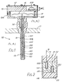
- the volume of gas flowing through a line 10 ( Figure 1), part of one wall 11 of which is shown, is to be metered, by means not shown, and referred to standard temperature and pressure conditions (T S , P S ) from the prevailing line conditions (T L ,P L ).
- T S , P S standard temperature and pressure conditions
- T L ,P L prevailing line conditions
- a signal varying in accordance with a correction function is required and to this end a sensor 12 in accordance with the present invention is arranged to sense line conditions.
- the sensor 12 has a sealed gas-containing chamber 14 having a bellows portion 15, in the form of a collapsible structure, sometimes referred to as a diaphragm, and a capillary portion 16, which extends within a probe portion 17 of sensor 12.
- Bellows 15 lies within an external chamber 18 formed within a thermally insulating casing 19.
- Probe portion 17 is bonded to casing 19 and adapted to be installed to enter the line 10.
- Capillary portion 16 extends within the probe portion 17 to a sub-chamber 100 within which is mounted a density sensor 101.
- Bellows portion 15, capillary portion 16 and sub-chamber 100 are sealed and contain an inert gas.
- the density sensor 101 is a vibratory element, formed in quartz for example in a tuning fork configuration.
- quartz sensors are known for the measurement of pressure and temperature, in which a quartz crystal is cut and configured to be sensitive to changes in a wanted parameter e.g. pressure, and insensitive to an unwanted parameter e.g. temperature: in the present case, the quartz is cut to be sensitive to changes in density.
- the quartz is normally made to resonate by feedback via a maintaining amplifier to and from piezo-electric transducers formed in the quartz, and the resonant frequency is a function of pressure and a sensor output is provided as a varying frequency signal.
- a similar arrangement is employed in the present embodiment, and to this end probe portion 17 houses a maintaining amplifier 102 mounted close to the vibratory element for the prevention of excessive electrical pick-up and the avoidance of stray capacitive loading.
- quartz element of the sensor 101 may still exhibit an unacceptable temperature characteristic.
- a reference crystal not subjected to the pressure to be measured, may be employed to apply a correction.
- a similar arrangement is employed with the density sensitive element of the present invention, and to this end a reference crystal 103 is mounted within probe portion 17 of the sensor 12, and excited similarly to the sensor 101 by means of another maintaining amplifier (not shown) associated with the maintaining amplifier 102.
- Chamber 18 within casing 19 is provided with an orifice 104 to which, in use, a connector (not shown) relays gas at line pressure, so that bellows portion 15 is subjected to line pressure P L .
- the connector may take any convenient form and for example run as a pipe from an adjacent line pressure tap.
- the gas in the sealed space defined within bellows 15, capillary portion 16 and sub-chamber 100 is itself at line pressure, P L .
- the displaceable volume of bellows 15 is relatively large compared with the volume of the capillary 16 and sub-chamber 100.
- Probe portion 17 fits within a standard thermowell 110 fitted in the wall 11 of the line 10, so as to maintain the gas in the sealed chamber at substantially line temperature T L .
- Capillary 16, chamber 100, reference sensor 103 and maintaining amplifier 102 are potted into the interior of probe portion 17 by use of a compound of suitable thermal conductivity. This serves not only to maintain the chamber 14 at line temperature, but also gives protection to the components, including the electrical connections 105, 106 intermediate the density sensor 101, reference sensor 103 and maintaining amplifier 102 (and its associated maintaining amplifier for sensor 103), and electrical connection 107 leading via conduit 108 to external connector 109.
- a vibratory quartz element is proportional to the density of the fluid by which it is surrounded and is also a function of temperature. Both of these characteristics have been successfully exploited to provide temperature and pressure sensors based on such elements.
- a vibratory element is mounted for example in a free gas
- dependence upon density is problematic since the density of fluid surrounding the sensor is itself dependent upon both temperature and pressure and therefore a density sensitive element cannot by itself be used to sense either pressure or temperature.
- the solution adopted in the prior art is to use two elements, one to compensate the other in respect of the unwanted parameter.
- a prior art pressure transducer includes two vibratory elements, one subjected to the pressure to be measured and one to a fixed pressure, both being maintained at the same temperature to provide compensation.
- a prior art temperature sensor would include two elements, one subject to the changing temperature to be measured and one to a fixed reference temperature, the pair being subjected to the same pressure. Such an arrangement is described, for example, in European Patent Application 0 101 669A.
- the present invention only a single density sensitive vibratory element is required.
- the element for example element 101 of Figure 1
- the element is contained in a chamber (16) in which there is a fixed mass of fluid.
- vibratory element 101 will exhibit a small temperature dependence of its own.
- the second crystal 103 maintained at the same temperature and in a fluid of constant density (conveniently a vacuum) is included.
- This second crystal which is formed from the same crystal growth and similarly cut, exhibits a substantially identical temperature dependence to measurement crystal 101 and may therefore be used for the cancellation of errors, for example by subtraction of a frequency count accumulated in a unit time interval from the measurement element count over the same time interval.
- elements 101 and 103 are mounted in an insert 22 of a material of high thermal conductivity, such as copper, to which capillary tube 16 may be attached to form chamber 100, the whole being made as a sub-assembly and inserted within the inner surface of probe 17, with which it is an interference fit.
- potting compound 23 may be applied.
- connection 20 between elements 101 and 103 and connection 21 between element 103 and the maintaining amplifier may be routed in any convenient way (connections 20 and 21 being shown diagrammatically in Figure 2), for example by conduits formed in insert 22 leading to passages formed by slots in the exterior of the insert in co-operation with the wall of the probe 17.
Landscapes
- General Physics & Mathematics (AREA)
- Physics & Mathematics (AREA)
- General Health & Medical Sciences (AREA)
- Life Sciences & Earth Sciences (AREA)
- Chemical & Material Sciences (AREA)
- Analytical Chemistry (AREA)
- Biochemistry (AREA)
- Fluid Mechanics (AREA)
- Immunology (AREA)
- Pathology (AREA)
- Health & Medical Sciences (AREA)
- Measuring Fluid Pressure (AREA)
- Measuring Volume Flow (AREA)
- External Artificial Organs (AREA)
- Transition And Organic Metals Composition Catalysts For Addition Polymerization (AREA)
- Geophysics And Detection Of Objects (AREA)
- Details Of Flowmeters (AREA)
- Investigating Or Analyzing Materials By The Use Of Electric Means (AREA)
- Reciprocating Pumps (AREA)
Claims (11)
une chambre étanche contenant du gaz (14); et
un moyen (15, 17) pour maintenir le gaz contenu à la température et à la pression de la canalisation;
le capteur étant caractérisé par un moyen de détection de densité à élément vibrant (101), disposé dans la chambre étanche (15) au contact du gaz contenu, pour produire un signal de sortie dont la fréquence dépend de la densité du gaz contenu.
Priority Applications (1)
| Application Number | Priority Date | Filing Date | Title |
|---|---|---|---|
| AT88307118T ATE74426T1 (de) | 1987-08-12 | 1988-08-02 | Aufnehmer zum korrigieren der messwerte eines gaszaehlers. |
Applications Claiming Priority (2)
| Application Number | Priority Date | Filing Date | Title |
|---|---|---|---|
| GB878719105A GB8719105D0 (en) | 1987-08-12 | 1987-08-12 | Fluid metering |
| GB8719105 | 1987-08-12 |
Publications (2)
| Publication Number | Publication Date |
|---|---|
| EP0311238A1 EP0311238A1 (fr) | 1989-04-12 |
| EP0311238B1 true EP0311238B1 (fr) | 1992-04-01 |
Family
ID=10622211
Family Applications (1)
| Application Number | Title | Priority Date | Filing Date |
|---|---|---|---|
| EP88307118A Expired - Lifetime EP0311238B1 (fr) | 1987-08-12 | 1988-08-02 | Palpeur de correction pour compteurs à gaz |
Country Status (7)
| Country | Link |
|---|---|
| US (1) | US5048323A (fr) |
| EP (1) | EP0311238B1 (fr) |
| JP (1) | JPS6459125A (fr) |
| AT (1) | ATE74426T1 (fr) |
| DE (1) | DE3869720D1 (fr) |
| ES (1) | ES2030171T3 (fr) |
| GB (2) | GB8719105D0 (fr) |
Cited By (2)
| Publication number | Priority date | Publication date | Assignee | Title |
|---|---|---|---|---|
| US8211052B1 (en) | 2006-07-13 | 2012-07-03 | Lexion Medical Llc | Charged hydrator |
| DE102013015218A1 (de) * | 2013-09-13 | 2015-03-19 | Hella Kgaa Hueck & Co. | Gassensor und Kraftfahrzeug mit einem Gassensor |
Families Citing this family (28)
| Publication number | Priority date | Publication date | Assignee | Title |
|---|---|---|---|---|
| US4885938A (en) * | 1988-12-16 | 1989-12-12 | Honeywell Inc. | Flowmeter fluid composition correction |
| US4961348A (en) * | 1988-12-16 | 1990-10-09 | Ulrich Bonne | Flowmeter fluid composition correction |
| US5339051A (en) * | 1991-12-09 | 1994-08-16 | Sandia Corporation | Micro-machined resonator oscillator |
| US5307668A (en) * | 1992-10-05 | 1994-05-03 | Badger Meter, Inc. | Gas density meter and method |
| EP0608736B1 (fr) * | 1993-01-25 | 2000-08-16 | Instromet, Inc. | Correcteur d'écoulement volumétrique avec un densitomètre |
| DE9416564U1 (de) * | 1994-10-14 | 1996-02-15 | Pector GmbH, 82054 Sauerlach | Vorrichtung zur Bestimmung der Zusammensetzung von Gasmischungen |
| US6352361B1 (en) | 1999-08-06 | 2002-03-05 | Pgi International | Temperature sensing device for metering fluids |
| US6390670B1 (en) | 1999-08-06 | 2002-05-21 | Pgi International Ltd. | Temperature sensing device for metering fluids |
| US6485175B1 (en) | 1999-08-06 | 2002-11-26 | Pgi International, Ltd. | Temperature sensing device for metering fluids |
| US6598481B1 (en) * | 2000-03-30 | 2003-07-29 | Halliburton Energy Services, Inc. | Quartz pressure transducer containing microelectronics |
| US6976489B2 (en) | 2000-06-30 | 2005-12-20 | Northgate Technologies, Inc. | Method and apparatus for humidification and warming of air |
| USD461173S1 (en) | 2000-11-22 | 2002-08-06 | Pgi International, Ltd. | Thermowell |
| US7784350B2 (en) * | 2007-02-07 | 2010-08-31 | Halliburton Energy Services, Inc. | Downhole transducer with adjacent heater |
| US10156480B2 (en) * | 2009-09-03 | 2018-12-18 | Rosemount Inc. | Thermowell vibration frequency diagnostic |
| US8737244B2 (en) | 2010-11-29 | 2014-05-27 | Rosemount Inc. | Wireless sensor network access point and device RF spectrum analysis system and method |
| US20130005372A1 (en) | 2011-06-29 | 2013-01-03 | Rosemount Inc. | Integral thermoelectric generator for wireless devices |
| DE102012100728A1 (de) * | 2012-01-30 | 2013-08-01 | Endress + Hauser Gmbh + Co. Kg | Vorrichtung zur Bestimmung und/oder Überwachung mindestens einer Prozessgröße |
| US9188488B2 (en) * | 2013-03-14 | 2015-11-17 | Rosemount Inc. | Vibration detection in thermowells |
| CN104165664B (zh) * | 2014-08-22 | 2017-06-20 | 辽宁毕托巴科技有限公司 | 毕托巴一体化质量流量计 |
| CN104236657A (zh) * | 2014-10-16 | 2014-12-24 | 辽宁毕托巴科技有限公司 | 一种毕托巴质量流量计 |
| EP3215812B1 (fr) | 2014-12-29 | 2020-10-07 | Concentric Meter Corporation | Capteur et dispositif de mesure de paramètre de fluide |
| US10126266B2 (en) | 2014-12-29 | 2018-11-13 | Concentric Meter Corporation | Fluid parameter sensor and meter |
| WO2016109451A1 (fr) | 2014-12-29 | 2016-07-07 | Concentric Meter Corporation | Transducteur électromagnétique |
| WO2016166610A2 (fr) * | 2015-04-14 | 2016-10-20 | Rheonics Gmbh | Capteur de viscosité à densité compensée en température, pourvu d'un élément de détection de résonance |
| US10502670B2 (en) | 2015-04-14 | 2019-12-10 | Rheonics, Gmbh | Temperature compensated density viscosity sensor having a resonant sensing element |
| US10996113B2 (en) * | 2017-09-29 | 2021-05-04 | Foreman Instrumentation & Controls, Inc. | Thermowell with expansion joint |
| CN112268589B (zh) * | 2020-10-15 | 2024-05-03 | 湖南常德牌水表制造有限公司 | 一种具有温度自适应密封结构的水表 |
| CN113340515B (zh) * | 2021-06-08 | 2025-01-03 | 布瑞特智联科技(杭州)有限公司 | 一种基于陶瓷电阻传感技术的压力传感器 |
Family Cites Families (11)
| Publication number | Priority date | Publication date | Assignee | Title |
|---|---|---|---|---|
| GB1065280A (en) * | 1965-03-22 | 1967-04-12 | Power Jets Res & Dev Ltd | Device for sensing changes in density of a gas |
| DE1573760A1 (de) * | 1966-12-23 | 1970-10-22 | Pintsch Bamag Ag | Vorrichtung zum UEberdruckschutz fuer elastisch verformbare Dosen,z.B. fuer die Messung von Druck und Temperatur eines Gases |
| DE2456751A1 (de) * | 1974-11-30 | 1976-08-12 | Hofmann Dieter Dr Phil Nat | Zustandsmengenumwerter fuer kleine variabilitaetsbereiche der zustandsgroessen |
| DE2633859A1 (de) * | 1976-07-28 | 1978-02-02 | Hofmann Dieter Dr Phil Nat | Elektronischer zustandsmengenumwerter nach dem vergleichsgasprinzip |
| GB2009931B (en) * | 1977-12-09 | 1983-04-27 | Solartron Electronic Group | Measurement of fluid density |
| US4238825A (en) * | 1978-10-02 | 1980-12-09 | Dresser Industries, Inc. | Equivalent standard volume correction systems for gas meters |
| JPS5838738B2 (ja) * | 1979-01-11 | 1983-08-25 | 横河電機株式会社 | 圧力計 |
| US4429564A (en) * | 1981-01-23 | 1984-02-07 | Yokogawa Hokushin Electric Corporation | Vibration type density meter |
| FR2532047A1 (fr) * | 1982-08-19 | 1984-02-24 | Asulab Sa | Capteur de mesure muni d'un resonateur piezo-electrique compense en temperature |
| US4574639A (en) * | 1983-06-21 | 1986-03-11 | Quartztronics, Inc. | Pressure force measurement apparatus and method |
| US4526480A (en) * | 1983-06-21 | 1985-07-02 | Quartztronics, Inc. | Fluid density temperature measurement apparatus and method |
-
1987
- 1987-08-12 GB GB878719105A patent/GB8719105D0/en active Pending
-
1988
- 1988-08-01 JP JP63192594A patent/JPS6459125A/ja active Pending
- 1988-08-02 DE DE8888307118T patent/DE3869720D1/de not_active Expired - Fee Related
- 1988-08-02 ES ES198888307118T patent/ES2030171T3/es not_active Expired - Lifetime
- 1988-08-02 AT AT88307118T patent/ATE74426T1/de not_active IP Right Cessation
- 1988-08-02 EP EP88307118A patent/EP0311238B1/fr not_active Expired - Lifetime
- 1988-08-04 GB GB8818328A patent/GB2208011B/en not_active Expired - Lifetime
- 1988-08-11 US US07/231,313 patent/US5048323A/en not_active Expired - Fee Related
Cited By (2)
| Publication number | Priority date | Publication date | Assignee | Title |
|---|---|---|---|---|
| US8211052B1 (en) | 2006-07-13 | 2012-07-03 | Lexion Medical Llc | Charged hydrator |
| DE102013015218A1 (de) * | 2013-09-13 | 2015-03-19 | Hella Kgaa Hueck & Co. | Gassensor und Kraftfahrzeug mit einem Gassensor |
Also Published As
| Publication number | Publication date |
|---|---|
| GB2208011B (en) | 1991-09-04 |
| ES2030171T3 (es) | 1992-10-16 |
| DE3869720D1 (de) | 1992-05-07 |
| EP0311238A1 (fr) | 1989-04-12 |
| GB8818328D0 (en) | 1988-09-07 |
| ATE74426T1 (de) | 1992-04-15 |
| US5048323A (en) | 1991-09-17 |
| JPS6459125A (en) | 1989-03-06 |
| GB2208011A (en) | 1989-02-15 |
| GB8719105D0 (en) | 1987-09-16 |
Similar Documents
| Publication | Publication Date | Title |
|---|---|---|
| EP0311238B1 (fr) | Palpeur de correction pour compteurs à gaz | |
| US4995263A (en) | Tuning fork quartz manometer | |
| US4599892A (en) | Volume measuring apparatus | |
| EP2667176B1 (fr) | Dispositif pour mesurer le vrai contenant d'un cylindre à gas sous pression | |
| US5410908A (en) | Measuring the quantity of a gas in a tank | |
| US5136885A (en) | Quartz crystal pressure sensor | |
| US4349881A (en) | Vibration instruments | |
| JPH03210446A (ja) | 差圧測定装置 | |
| US5596147A (en) | Coplanar pressure sensor mounting for remote sensor | |
| US4625564A (en) | Vortex flow meter | |
| JP2790351B2 (ja) | 音叉形水晶圧力測定方法およびその装置 | |
| US6079266A (en) | Fluid-level measurement by dynamic excitation of a pressure- and fluid-load-sensitive diaphragm | |
| EP0609616B1 (fr) | Résonateur cristallin pour la mesure de la température | |
| US6279405B1 (en) | Apparatus and method for a pressure monitoring device | |
| US20070017277A1 (en) | Apparatus and method for measuring fluid density | |
| US20070017278A1 (en) | Apparatus and method for measuring fluid density | |
| JPH0515975B2 (fr) | ||
| US20250027828A1 (en) | Pressure sensor, in particular for pressures of more than 100 bar | |
| US3502969A (en) | Error correction in capacitive gages | |
| RU2627544C2 (ru) | Пьезорезонансно-вязкостный вакуумметр | |
| JPS6076637A (ja) | 半導体圧力計 | |
| SU1464057A1 (ru) | Микробарометр | |
| US3010322A (en) | Pressure responsive devices and systems therefor | |
| RU1816318C (ru) | Устройство дл измерени давлени | |
| JPS63171335A (ja) | 圧電型圧力計の温度補償方式 |
Legal Events
| Date | Code | Title | Description |
|---|---|---|---|
| PUAI | Public reference made under article 153(3) epc to a published international application that has entered the european phase |
Free format text: ORIGINAL CODE: 0009012 |
|
| AK | Designated contracting states |
Kind code of ref document: A1 Designated state(s): AT CH DE ES FR IT LI NL |
|
| 17P | Request for examination filed |
Effective date: 19891009 |
|
| 17Q | First examination report despatched |
Effective date: 19910319 |
|
| GRAA | (expected) grant |
Free format text: ORIGINAL CODE: 0009210 |
|
| ITF | It: translation for a ep patent filed | ||
| AK | Designated contracting states |
Kind code of ref document: B1 Designated state(s): AT CH DE ES FR IT LI NL |
|
| PG25 | Lapsed in a contracting state [announced via postgrant information from national office to epo] |
Ref country code: LI Effective date: 19920401 Ref country code: CH Effective date: 19920401 Ref country code: AT Effective date: 19920401 |
|
| REF | Corresponds to: |
Ref document number: 74426 Country of ref document: AT Date of ref document: 19920415 Kind code of ref document: T |
|
| REF | Corresponds to: |
Ref document number: 3869720 Country of ref document: DE Date of ref document: 19920507 |
|
| ET | Fr: translation filed | ||
| REG | Reference to a national code |
Ref country code: CH Ref legal event code: PL |
|
| REG | Reference to a national code |
Ref country code: ES Ref legal event code: FG2A Ref document number: 2030171 Country of ref document: ES Kind code of ref document: T3 |
|
| PLBE | No opposition filed within time limit |
Free format text: ORIGINAL CODE: 0009261 |
|
| STAA | Information on the status of an ep patent application or granted ep patent |
Free format text: STATUS: NO OPPOSITION FILED WITHIN TIME LIMIT |
|
| 26N | No opposition filed | ||
| PGFP | Annual fee paid to national office [announced via postgrant information from national office to epo] |
Ref country code: FR Payment date: 19940722 Year of fee payment: 7 |
|
| PGFP | Annual fee paid to national office [announced via postgrant information from national office to epo] |
Ref country code: ES Payment date: 19940805 Year of fee payment: 7 |
|
| PGFP | Annual fee paid to national office [announced via postgrant information from national office to epo] |
Ref country code: NL Payment date: 19940831 Year of fee payment: 7 |
|
| PGFP | Annual fee paid to national office [announced via postgrant information from national office to epo] |
Ref country code: DE Payment date: 19940927 Year of fee payment: 7 |
|
| PG25 | Lapsed in a contracting state [announced via postgrant information from national office to epo] |
Ref country code: ES Free format text: LAPSE BECAUSE OF NON-PAYMENT OF DUE FEES Effective date: 19950803 |
|
| PG25 | Lapsed in a contracting state [announced via postgrant information from national office to epo] |
Ref country code: NL Effective date: 19960301 |
|
| PG25 | Lapsed in a contracting state [announced via postgrant information from national office to epo] |
Ref country code: FR Effective date: 19960430 |
|
| NLV4 | Nl: lapsed or anulled due to non-payment of the annual fee |
Effective date: 19960301 |
|
| PG25 | Lapsed in a contracting state [announced via postgrant information from national office to epo] |
Ref country code: DE Effective date: 19960501 |
|
| REG | Reference to a national code |
Ref country code: FR Ref legal event code: ST |
|
| REG | Reference to a national code |
Ref country code: ES Ref legal event code: FD2A Effective date: 19990503 |
|
| PG25 | Lapsed in a contracting state [announced via postgrant information from national office to epo] |
Ref country code: IT Free format text: LAPSE BECAUSE OF NON-PAYMENT OF DUE FEES;WARNING: LAPSES OF ITALIAN PATENTS WITH EFFECTIVE DATE BEFORE 2007 MAY HAVE OCCURRED AT ANY TIME BEFORE 2007. THE CORRECT EFFECTIVE DATE MAY BE DIFFERENT FROM THE ONE RECORDED. Effective date: 20050802 |