EP0311363A2 - Hohler Stahlpfahl, Erzeugungsmethode und Methode zum Einrammen eines Pfahles - Google Patents
Hohler Stahlpfahl, Erzeugungsmethode und Methode zum Einrammen eines Pfahles Download PDFInfo
- Publication number
- EP0311363A2 EP0311363A2 EP88309254A EP88309254A EP0311363A2 EP 0311363 A2 EP0311363 A2 EP 0311363A2 EP 88309254 A EP88309254 A EP 88309254A EP 88309254 A EP88309254 A EP 88309254A EP 0311363 A2 EP0311363 A2 EP 0311363A2
- Authority
- EP
- European Patent Office
- Prior art keywords
- pile
- hollow steel
- extremity end
- steel pile
- projection
- Prior art date
- Legal status (The legal status is an assumption and is not a legal conclusion. Google has not performed a legal analysis and makes no representation as to the accuracy of the status listed.)
- Granted
Links
- 229910000831 Steel Inorganic materials 0.000 title claims abstract description 82
- 239000010959 steel Substances 0.000 title claims abstract description 82
- 238000000034 method Methods 0.000 title claims abstract description 32
- 238000004519 manufacturing process Methods 0.000 title claims description 4
- 239000002689 soil Substances 0.000 claims description 45
- 238000003825 pressing Methods 0.000 claims description 12
- 230000007246 mechanism Effects 0.000 claims description 8
- 238000003466 welding Methods 0.000 claims description 8
- 238000005520 cutting process Methods 0.000 claims description 6
- 230000008569 process Effects 0.000 abstract description 12
- 230000035515 penetration Effects 0.000 description 44
- 238000009412 basement excavation Methods 0.000 description 20
- XEEYBQQBJWHFJM-UHFFFAOYSA-N Iron Chemical compound [Fe] XEEYBQQBJWHFJM-UHFFFAOYSA-N 0.000 description 12
- 230000000694 effects Effects 0.000 description 9
- 238000012360 testing method Methods 0.000 description 7
- 238000007596 consolidation process Methods 0.000 description 6
- 238000007599 discharging Methods 0.000 description 6
- 229910052742 iron Inorganic materials 0.000 description 6
- 230000009471 action Effects 0.000 description 4
- 239000004576 sand Substances 0.000 description 4
- 241000282693 Cercopithecidae Species 0.000 description 3
- 239000004567 concrete Substances 0.000 description 3
- 230000000149 penetrating effect Effects 0.000 description 3
- 230000008878 coupling Effects 0.000 description 2
- 238000010168 coupling process Methods 0.000 description 2
- 238000005859 coupling reaction Methods 0.000 description 2
- 238000010586 diagram Methods 0.000 description 2
- 238000005553 drilling Methods 0.000 description 2
- 238000002474 experimental method Methods 0.000 description 2
- 230000004907 flux Effects 0.000 description 2
- 230000002093 peripheral effect Effects 0.000 description 2
- 230000009467 reduction Effects 0.000 description 2
- 230000004044 response Effects 0.000 description 2
- 238000002834 transmittance Methods 0.000 description 2
- 230000015572 biosynthetic process Effects 0.000 description 1
- 238000009833 condensation Methods 0.000 description 1
- 230000005494 condensation Effects 0.000 description 1
- 230000003247 decreasing effect Effects 0.000 description 1
- 230000000881 depressing effect Effects 0.000 description 1
- 239000003112 inhibitor Substances 0.000 description 1
- 238000005259 measurement Methods 0.000 description 1
- 239000011178 precast concrete Substances 0.000 description 1
- 239000011513 prestressed concrete Substances 0.000 description 1
- 238000012545 processing Methods 0.000 description 1
- 239000011150 reinforced concrete Substances 0.000 description 1
- 238000005096 rolling process Methods 0.000 description 1
Images


Classifications
-
- E—FIXED CONSTRUCTIONS
- E02—HYDRAULIC ENGINEERING; FOUNDATIONS; SOIL SHIFTING
- E02D—FOUNDATIONS; EXCAVATIONS; EMBANKMENTS; UNDERGROUND OR UNDERWATER STRUCTURES
- E02D5/00—Bulkheads, piles, or other structural elements specially adapted to foundation engineering
- E02D5/22—Piles
- E02D5/24—Prefabricated piles
-
- B—PERFORMING OPERATIONS; TRANSPORTING
- B23—MACHINE TOOLS; METAL-WORKING NOT OTHERWISE PROVIDED FOR
- B23K—SOLDERING OR UNSOLDERING; WELDING; CLADDING OR PLATING BY SOLDERING OR WELDING; CUTTING BY APPLYING HEAT LOCALLY, e.g. FLAME CUTTING; WORKING BY LASER BEAM
- B23K5/00—Gas flame welding
- B23K5/18—Gas flame welding for purposes other than joining parts, e.g. built-up welding
-
- E—FIXED CONSTRUCTIONS
- E02—HYDRAULIC ENGINEERING; FOUNDATIONS; SOIL SHIFTING
- E02D—FOUNDATIONS; EXCAVATIONS; EMBANKMENTS; UNDERGROUND OR UNDERWATER STRUCTURES
- E02D5/00—Bulkheads, piles, or other structural elements specially adapted to foundation engineering
- E02D5/22—Piles
- E02D5/24—Prefabricated piles
- E02D5/28—Prefabricated piles made of steel or other metals
-
- E—FIXED CONSTRUCTIONS
- E02—HYDRAULIC ENGINEERING; FOUNDATIONS; SOIL SHIFTING
- E02D—FOUNDATIONS; EXCAVATIONS; EMBANKMENTS; UNDERGROUND OR UNDERWATER STRUCTURES
- E02D5/00—Bulkheads, piles, or other structural elements specially adapted to foundation engineering
- E02D5/22—Piles
- E02D5/56—Screw piles
-
- E—FIXED CONSTRUCTIONS
- E02—HYDRAULIC ENGINEERING; FOUNDATIONS; SOIL SHIFTING
- E02D—FOUNDATIONS; EXCAVATIONS; EMBANKMENTS; UNDERGROUND OR UNDERWATER STRUCTURES
- E02D7/00—Methods or apparatus for placing sheet pile bulkheads, piles, mouldpipes, or other moulds
- E02D7/22—Placing by screwing down
-
- E—FIXED CONSTRUCTIONS
- E21—EARTH OR ROCK DRILLING; MINING
- E21B—EARTH OR ROCK DRILLING; OBTAINING OIL, GAS, WATER, SOLUBLE OR MELTABLE MATERIALS OR A SLURRY OF MINERALS FROM WELLS
- E21B7/00—Special methods or apparatus for drilling
- E21B7/20—Driving or forcing casings or pipes into boreholes, e.g. sinking; Simultaneously drilling and casing boreholes
- E21B7/201—Driving or forcing casings or pipes into boreholes, e.g. sinking; Simultaneously drilling and casing boreholes with helical conveying means
Definitions
- This invention relates to a hollow steel pile having open ends, and more particularly a hollow steel pile, a method of execution of work for a hollow steel pile, a device for forming an inner spiral rib at an extremity end of the hollow steel pile and a method for forming the spiral rib by utilizing the spiral rib forming device.
- the hollow steel pile is settled in the ground through a rotary press-in method.
- the hollow steel pile is provided with some saw-teeth or with a cutting tool at the extremity end of the steel pipe and the pile is held at its head with a rotary device and twisted into the ground through its rotational force.
- a hollow steel pile having at its extremity end or intermediate part some excavation vanes or screws also at the outer periphery or inner periphery of the hollow steel pile having open ends is already proposed in Japanese Patent Laid-Open No.62-86224 and the like.
- screw vanes are provided at the extremity end of the hollow steel pile as well as at the circumferential surface of the intermediate part, the pile is held at the head by the rotary device and is settled into the ground with a weight of the device and the rotary pulling action of the screw vanes.
- the peripheral surface of the main body of the pile is formed with one or plurality of helical bands to cause a bearing area of the pile to be increased and the ground around the pile is press fitted by the helical bands, so that it is expected that the bearing force for the pile is increased and a stability of the pile becomes a superior one.
- an internal excavation method which can be applied to the hollow steel pile.
- This internal excavation process is applied to the stratum having an intermediate sand layer having a relative high N-value until the pile is reached to the bearing stratum.
- the pile to be used in this process is limited to one having a hollow circular section in view of its feature, wherein a spiral auger is inserted into the hollow part and the pile is settled down into a desired depth by its own weight and a pressing-in device while the excavated soil is discharged from the pile head through the hollow part of the pile. After the pile is reached to the desired depth, the pile is penetrated into the bearing layer so as to realize the bearing force.
- the bearing force realizing process there are three types of
- the pile driving method has a problem of noise and vibration and the consolidation method of foundation has a problem in which an extremity end bearing force is lower than that of the driving pile, in particular in case of the hollow steel pile, a sectional area of the pile itself is small, an adhesion of the consolidation concrete to the pile wall becomes insufficient due to a presence of the excavated soil adhered to the inner surface of the pile and shows a certain problem in realizing the bearing force.
- the method improving this disadvantage is an enlarged consolidation method of foundation.
- a special auger head is used and requires a bottom enlargement excavation process. It further has disadvantages that a slime of the lower part of the consolidation concrete of foundation can not be removed completely and it requires much time to set the concrete.
- the soil is filled within the pile.
- An entering amount of soil into the pile is limited by a frictional resistance between the inner wall of the pile and the soil which restricts a penetration speed of the pile.
- a certain range of frictional resistance of the inner wall of the pile in general less than about 2 times of the diameter
- the frictional resistance of the inner wall of the pile of the in-pile soil more the height becomes a resistance when the pile is penetrated so as to eliminate the pile penetration speed.
- a spiral rib is provided at the inner circumference of the extremity end of the pile.
- Another object of the present invention is to provide a steel pipe pile sufficiently consolidated for the foundation against the bearing stratum under an effect of screwing operation of the inner wall and at the same time a friction is generated between the soil column in the pipe kept at a proper consolidated state and the inner wall, resulting in that a higher bearing force can be attained irrespective of a simple and easy execution of work.
- the present invention has been proposed in view of the above-described circumstances and its main gist consists in a system in which a helical projection composed of a round rod or a rectangular rod with a projection height of 20 mm or less is arranged over a length of about 10 times or less of a pile diameter at an outer circumference of the extremity end of the steel pipe pile having open ends, the projection is also arranged at the inner circumference of the extremity end of the pile.
- the present invention has an arrangement in which an inner diameter size of a desired length at the extremity end of the hollow steel pile having open ends is reduced, a wall thickness of the pipe is made slightly thick.
- An inner spiral rib forming device is constructed such that a fixing base frame body is assembled in such a way as it may be moved axially and slidably in respect to the lateral core body and may not be moved axially and circumferentially from a bearing block to be inserted into the extremity end part of the worked and machined steel pipe, the fixing base frame is provided with a plurality of suspended legs having at their extremity ends spiral rib holding rollers in axial spaced-apart relation thereto, a preceding suspended leg pressing part is provided with a torch directed and set, and the opposite sides of the suspended legs are provided with pressing rollers abutting against the inner surface of the hollow steel pile.
- a pile driving method of the present invention employing the above-mentioned hollow steel pile is characterized in pressing the pile in down to a bearing stratum layer and screwing it into the bearing layer.
- Another pile driving method is characterized in inserting a spiral auger into a hollow part of the pile, pressing down the pile to a bearing stratum layer while the soil being discharged by the auger head, and then screwing the pile into the bearing layer.
- a first preferred embodiment of the present invention is a hollow steel pile having a helical projection of 20 mm or less in height at an outer circumference at a length part of less than 10 times of a diameter of the pile.
- Fig. 1 is an entire view for showing the hollow steel pile of the present invention
- Fig. 2 is an enlarged detail view for showing an extremity end part of the hollow steel pile of the present invention
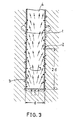
- Fig. 3 is an illustrative view for showing a penetration mechanism for soil into the pile in the present invention.
- a reference numeral 1 indicates a hollow steel pile having open ends and a helical projection 2 composed of a round rod or a rectangular member with a projection height of 20 mm or less is welded to an outer circumference of the extremity end of the pile over a length of about 10 times or less of a pile diameter.
- An attaching length of the helical projection 2 is preferably short as an excessive length may cause a desired torque for use in performing a rotary pressing-in operation to be increased uselessly and to delay the penetration time and further may increase the degree of disturbance of the ground to require a long period of time for recovering the frictional pile force at its circumferential surface.
- too short length of the projection may not provide any excavation function and a circumferential friction resistance force.
- the frictional surface is an outer circumferential surface of the pile and even if a slight projection height may realize the screwing effect, so that the lower projection height is satisfactory and so the discharging soil could be eliminated.
- the most important feature of the above-mentioned constitution consists in the fact that the excavation vanes are made of round rod or rectangular rod member and in addition it consists in a less cost, a provision of the associated strength with a simple welding work and an economical effectiveness.
- the projection 3 may increase the frictional resistance force against the soil within the pile and the bearing force at the extremity end of the pile is provided.
- In-pile screw projection 3 is required to be attached in a range more than at least two times or more of a diameter where the load at the extremity end may act to increase the load at the side wall of the extremity end of the pile and further it is attached at the range more than five times of the diameter in order to realize the effect of the screw.
- a helical shape as well as a pitch of the helical line and its length is not necessarily the same as that of the outer circumference and its selection may influence on the penetration speed torque.
- the penetrated soil 4 in the pile 1 shows a sliding action at the extremity end of the pile and the in-pile soil 4 may accept a transmittance of torque from the extremity end, generates a relative speed between the pile 1 and the in-pile soil 4 and then penetrates into the pile while being rotated.
- the in-pile soil column 4 is rotated to reduce a dynamic frictional resistance at the inner surface of the pile and is pushed up with a screw thrust and with a load at the extremity end generated as the soil is rotated.
- the extremity end of the pile 1 is made as a saw-tooth 5 or is provided with bite 6 for excavating a width corresponding to a value added with heights of projections 2 and 3 and the pipe wall thickness, a penetrating efficiency is improved more.
- the pile was penetrated down to a depth of 21 m at the stratum with a N-value of 50 in about 60 minutes. No discharging soil is found at all.
- the effect of the inner screw is particularly effective at the sand layer having a long penetration time and further it is confirmed that a total penetration time can be reduced.
- a second preferred embodiment of the present invention provides a hollow steel pile having reduced open end.
- the extremity end bearing force is maintained with the extremity end frictional force increased by a narrowed spacing, the entered soil at the small diameter part of the pile is loosely passed at the large inner diameter part to reduce the inner wall friction of the penetrated soil, penetration of the pile is improved to reduce a desired torque when screwed.
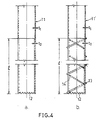
- Figs. 4a and 4b are a longitudinal section for showing a steel hollow pile of the present invention, wherein Fig. 4a indicates a case in which the helical projection composed of a round rod or a rectangular rod is not provided and in turn Fig. 4b indicates a case in which the helical projection is provided.
- the inner diameter size of a desired length l at the extremity end is made small as will and a pile wall thickness t2 only at this portion is made slightly thicker than a pile wall thickness t1 at other part.
- a reference numeral 12 in the figure denotes a saw-tooth.
- the penetrated soil in the pile is cut in a smaller diameter than that of the conventional system and the inner wall friction of the penetrated soil is reduced and thereby a desired torque is also reduced.
- the hollow steel pile 11′ has a helical projection 13 composed of a round rod or rectangular rod having a height of 20 mm or less which is welded at the outer circumference of the extremity end over a length of less than ten times of a diameter of the pile.
- the attaching length of the above-described helical projection 13 if the length is too long, the desired torque for use in performing a rotary pressing-in operation is increased uselessly to delay the penetration time and to increase a degree of disturbance of stratum as well as to require a longer period of time for recovering the frictional resistance force at the circumferential surface, so that the shorter attaching length is preferable.
- too short attaching length may not provide an excavation capability and a resistance force at the circumferential surface.
- the pile In case that the pile is to be penetrated into a hard stratum and its penetration time is extended, it is effective to provide the helical projection 14 in the pile and the in-pile screw thrusting force may reduce the penetrating time. In addition, after penetration, the projection 14 may increase the frictional resistance force against the soil in the pile and produce the bearing force at the extremity end of the pile.
- the in-pile screw projection 14 is required to be attached at a range at least more than two times of a diameter where the load at the extremity end may act to increase the load at the side wall of the extremity end of the pile and in order to realize the effect of the screw, the projection is attached by more than five times of the diameter.
- a shape of the helical part as well as a helical pitch and a length of the helical part may not necessarily be the same as that of the outer circumference, although their selection amy influence against the penetration speed torque.
- Fig. 5 is illustrated a difference of penetration torque in each of the piles having projections 13 and 14 between one having a pile wall thickness at the extremity end of the pile slightly thick as disclosed in the present invention and the other having no thick pile wall thickness.
- a line 15 in Fig. 5 indicates a case of the hollow steel pile in which a projection 13 having a pitch of 300 mm and a length of 3,000 mm is arranged at an outer circumference of the extremity end of the steel pile having the same wall thickness of an example of comparison and a projection 14 having a pitch of 300 mm and a length of 3,000 mm is arranged at an inner circumference of the steel pile.
- a line 16 in this figure indicates the arrangement of the present invention in which the same projections 13 and 14 as described above are arranged at the pile having a small inner diameter of the extremity end and a thick wall thickness.
- Fig. 6 is illustrated a relation between a length of the projection 14 and a penetration speed.
- Lines 17 and 18 in the figure correspond to the lines 15 and 16, and the line 19 corresponds to one in which the projection 14 of the lines 15 and 17 is reduced to a length of 1,500 mm of a half of the former one. It is apparent that a length of the projection 14 may remarkably influence the penetration speed.
- a third preferred embodiment of the present invention provides pile driving method employing a hollow steel pile, especially in case of applying an internal excavation process.
- a spiral auger is inserted into a hollow part of the hollow steel pile, the pile is settled down by its own weight and a pressing-in device while the excavation and soil discharging are being carried out by the auger head, and upon reaching to the bottom, the required length of the pile is screwed into and penetrated into the desired stratum, thereby a high frictional resistance is generated between the pile penetrated soil column enclosed and restricted and the inner wall surface of the pile through the screw-like projection and when a bearing force which is approximate to the monkey direct driving pile is realized.
- Figs. 7a and 7b illustrate a process of screwing and excavation of a hollow steel pile as applied in the work of the present invention in case of performing the internal excavation process together.
- Fig. 8 illustrates in-pile penetration mechanism in the present invention.
- Fig. 9(i) to (vi) illustrate an order of work for the case of performing the internal excavation together.
- a hollow steel pile 1 used in the execution of work of the present invention has a screw projection 22 at an inner wall of the extremity end of the pile.
- the screw projection 22 is constructed such that an iron bar is normally welded in a spiral form.
- a projection is provided at a stage of plate rolling and a screw projection is applied.
- the spiral auger 23 is inserted into a hollow part of the hollow steel pile 21 and settled down by a weight of the pile itself and a pressing-in device while being excavated and discharging down to the desired stratum acting as a bearing layer 24 by a auger head 23a.
- a reference numeral 25 denotes a friction cutter
- a reference numeral 26 denotes a screw projection arranged outside the pile.
- the hollow steel pile 21 shown in the drawing is illustrated as a stepped form which is communicated with a cylindrical part having a small diameter through a metering part, a normal type of straight cylinder form may also be applicable.
- the soil entered into the pile from the extremity end is pushed up in sequence by a load at the extremity end of the pile and the screw thrusting force in the pile.
- the pile is rotated at a faster number of rotation than that corresponding to a screw pitch and a penetration speed and shows a sliding movement at the extremity end of the pile, the soil in the pile transmits a torque from its extremity end to generate a relative speed between the pile and the soil in the pile and then penetrates into the soil while being rotated.
- the soil column in the pile makes the frictional resistance at the surface of the pile as a dynamic friction resistance as the pile is rotated and the soil in the pile is pushed up by a screw thrusting force and a load at the extremity end of the pile generated as the pile is rotated.
- Fig. 8 is illustrated the above-mentioned in-pile penetration mechanism.
- a transmittance torque is also increased and at the same time a resistance of the inner wall at the extremity end of the pile is increased, so that the increasing of the load at the extremity end of the pile does not effectively act against the penetration of the soil into the pipe.
- the screw projection in the pile is required to be attached in a range at least more than two times of a diameter d to which the load at the extremity end may act to increase the load at the extremity end of the pile.
- the screws projection arranged at the outer surface of the pile may cut the ground under an action to excavate the stratum out of the outer circumference of the pile upwardly.
- the projection attached to the outer circumference of the pile is not necessarily a spiral iron rod and it is sometimes applied to have only the general type of friction cutter at the extremity end of the pile.
- an arrangement of a spiral iron rod over a certain length of the extremity end of the outer circumference of the pile enables a desired torque generated during its penetration to be decreased, and after penetration work, it may increase a friction resistance force between the bearing layer and the outer circumference of the pile and realize the bearing force.
- the intermediate excavation processes of (i) to (v) may be eliminated and the pile and the auger drill machine may be connected at first, rotated and pressed in.
- a feature of the above-described arrangement of the present invention consists in the fact that the hollow steel pile having screw projection attached to the inner wall of the extremity end of the pile is screwed into the ground and penetrated into it.
- Examples of the execution of work of a pile having a size of 400 ⁇ x 22 m are compared with one having an inner wall screw and the other having no inner wall screw.
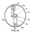
- Figs. 10a and 10b are an illustrative view for showing a state of use of the device of the present invention.
- Fig. 10a is a view taken along a line b-b.
- a reference numeral 31 designates a lateral core body inserted into an extremity end of a machined and preformed steel pipe 32 composed of a rectangular steel pipe and the like which is projected out of a fixed supporting table not shown.
- a fixing base frame 33 which can be axially slid of the core body 31 and not rotatable in an axial circumferential direction.
- the fixing base frame 33 is provided with a plurality of suspending legs 34, Vietnamese spacing (a spiral pitch) in an axial direction, and the extremity ends of the suspending legs 34 are provided with spiral rib holding rollers 34a.
- a torch 35 From the fixing base frame 33 is projected a torch 35 and this is directed near the rollers 34a preceding so as to press and set a position of the spiral rib 36 not yet welded as shown.
- a pressing roller 37 abutting against an inner surface of the steel pile 32 having a pressurizing mechanism such as a spring 37a installed so as to press the rollers 34a against the inner surface of the steel pile 32 is provided.
- the rib 36 composed of a round rod or rectangular rod formed in a spiral form in advance is inserted into the extremity end of the already-formed steel pile 32, only the open end where an operator may manually reach is welded at 8 by hand for a temporarily fixing and fixed there.
- the steel pile 32 is mounted on a rotary device such as a turning roller and the like not shown.
- the above-mentioned device is inserted into the extremity end of the steel pile 32 maintained in this condition, the rollers 34a hold the spiral rib 36 and the pressing roller 37 is abutted against the inner surface of the steel pile 32.
- the preceding roller 34a holds the rib 36 not yet welded at a desired spiral pitch position in reference to the rollers 34a for holding the rib 36 temporarily fixed to the open end under a rotation of the steel pile 32 and at the same time it is welded with the torch 35 at once.
- the fixing base frame 33 is relatively advanced into the steel pile 32 so as to complete automatically the formation of the spiral rib at the inner surface of the extremity end over a desired length.
- the torch 35 is required to be compact in size, it is preferable not to provide any flux supplying device and the like, i.e. to use a flux cored wire.
- the welding position of the torch 35 is directed downwardly as described above and fixed, and a stable welding can be made.
- the pressing roller 37 it must be considered that a uniform pressing pressure is maintained against a group of rollers 34a and the spiral rib 36 may not act as an inhibitor and so a symmetrical arrangement or a plurality of steps of pressing rollers should be made.
- the above-described device is operated such that the rib which is formed in a spiral form in advance is inserted into the extremity end part and only the open end part manually reached is welded by a manual operation and fixed and then inserted into the extremity end of the already formed steel pipe laterally installed on the rotary device.
- the spiral rib pushed against the inner surface of the steel pile with a pushing force of the pressurizing rollers through the spiral rib holding rollers are welded in sequence through torch as the steel pile is rotated.
- an iron rib of 13 ⁇ was welded to an inner wall of a pile having an inner diameter of 300 ⁇ , a length of 15 m, a length of extremity end of 3000 mm, resulting in that the welding could be performed without any problem and its quality condition was assured.
Landscapes
- Engineering & Computer Science (AREA)
- Structural Engineering (AREA)
- Life Sciences & Earth Sciences (AREA)
- Mining & Mineral Resources (AREA)
- General Life Sciences & Earth Sciences (AREA)
- Civil Engineering (AREA)
- Paleontology (AREA)
- General Engineering & Computer Science (AREA)
- Geology (AREA)
- Mechanical Engineering (AREA)
- Physics & Mathematics (AREA)
- Environmental & Geological Engineering (AREA)
- Fluid Mechanics (AREA)
- Geochemistry & Mineralogy (AREA)
- Piles And Underground Anchors (AREA)
Applications Claiming Priority (8)
| Application Number | Priority Date | Filing Date | Title |
|---|---|---|---|
| JP62251381A JPH0194112A (ja) | 1987-10-05 | 1987-10-05 | 鋼管杭の施工法 |
| JP251381/87 | 1987-10-05 | ||
| JP286855/87 | 1987-11-13 | ||
| JP62286855A JP2512503B2 (ja) | 1987-11-13 | 1987-11-13 | ドリル鋼管杭 |
| JP302492/87 | 1987-11-30 | ||
| JP62302492A JPH01146011A (ja) | 1987-11-30 | 1987-11-30 | ドリル鋼管杭 |
| JP63050715A JPH07899B2 (ja) | 1988-03-04 | 1988-03-04 | ドリル鋼管杭に於ける先端内設スパイラルリブの付形装置と当該装置を利用したスパイラルリブ付形方法 |
| JP50715/88 | 1988-03-04 |
Publications (3)
| Publication Number | Publication Date |
|---|---|
| EP0311363A2 true EP0311363A2 (de) | 1989-04-12 |
| EP0311363A3 EP0311363A3 (en) | 1989-11-15 |
| EP0311363B1 EP0311363B1 (de) | 1993-03-31 |
Family
ID=27462538
Family Applications (1)
| Application Number | Title | Priority Date | Filing Date |
|---|---|---|---|
| EP88309254A Expired - Lifetime EP0311363B1 (de) | 1987-10-05 | 1988-10-05 | Hohler Stahlpfahl, Erzeugungsmethode und Methode zum Einrammen eines Pfahles |
Country Status (4)
| Country | Link |
|---|---|
| US (1) | US5137394A (de) |
| EP (1) | EP0311363B1 (de) |
| KR (1) | KR940004906B1 (de) |
| DE (1) | DE3879842T2 (de) |
Cited By (4)
| Publication number | Priority date | Publication date | Assignee | Title |
|---|---|---|---|---|
| FR2798420A1 (fr) * | 1999-09-15 | 2001-03-16 | Cie Du Sol | Outil de forage muni d'un tubage |
| EP1132525A1 (de) * | 2000-03-10 | 2001-09-12 | Compagnie Du Sol | Aushubgerät für die Herstellung von Ortbetonpfählen |
| CN107513999A (zh) * | 2017-08-22 | 2017-12-26 | 苏交科集团股份有限公司 | 一种快速打桩装置 |
| CN112921954A (zh) * | 2021-04-18 | 2021-06-08 | 刘慧� | 一种新型装配式加固钢管桩及其制作方法 |
Families Citing this family (13)
| Publication number | Priority date | Publication date | Assignee | Title |
|---|---|---|---|---|
| USD397345S (en) | 1996-10-08 | 1998-08-25 | Kejr Engineering, Inc. | Probe rod thread |
| US6030150A (en) * | 1998-02-25 | 2000-02-29 | Dana A. Schmednecht | Method and apparatus for constructing subterranean walls comprised of granular material |
| US6231270B1 (en) | 1999-05-27 | 2001-05-15 | Frank Cacossa | Apparatus and method of installing piles |
| US6709200B1 (en) * | 2002-11-01 | 2004-03-23 | Milton Reynolds | Method of constructing the foundation and support structure for elevated transportation systems |
| US7267510B2 (en) * | 2003-07-29 | 2007-09-11 | Cable Lock, Inc. | Foundation pile having a spiral ridge |
| US7185538B2 (en) * | 2004-11-12 | 2007-03-06 | Honeywell International Inc. | Methods and systems for sensing air vehicle airspeed |
| JP5518050B2 (ja) * | 2009-04-10 | 2014-06-11 | 新日鉄住金エンジニアリング株式会社 | 鋼管杭及び鋼管杭の施工方法 |
| KR101586461B1 (ko) * | 2014-11-10 | 2016-02-03 | 주식회사 대명테크놀 | 농업용 낙뢰 보호장치 |
| KR101682446B1 (ko) | 2016-06-07 | 2016-12-05 | 주식회사 코마스 | 오탁방지막용 강관말뚝앙카 및 그 박음장치 |
| US10648146B1 (en) | 2017-12-22 | 2020-05-12 | Martin Reulet | Precast concrete screw cylinder system and method for soil stabilization and erosion control |
| RU181282U1 (ru) * | 2018-04-02 | 2018-07-09 | Федеральное государственное бюджетное образовательное учреждение высшего образования "Санкт-Петербургский государственный архитектурно-строительный университет" | Винтовая свая |
| JP2020180436A (ja) * | 2019-04-23 | 2020-11-05 | 東電設計株式会社 | 杭基礎及び杭基礎の施工方法 |
| DE102024107581B4 (de) * | 2024-03-18 | 2026-02-12 | Geosystem Gbk Gmbh | Vorrichtung und Verfahren zur Tiefengründung von Fundamenten für Lärm- und Sichtschutzbauten |
Family Cites Families (16)
| Publication number | Priority date | Publication date | Assignee | Title |
|---|---|---|---|---|
| US109337A (en) * | 1870-11-15 | Improvement in screw-piles | ||
| GB1391110A (en) * | 1972-09-11 | 1975-04-16 | Turzillo L A | Methods and means for producing pile or like structural columns in situ |
| US3842608A (en) * | 1972-11-28 | 1974-10-22 | L Turzillo | Method and means for installing load bearing piles in situ |
| US4156471A (en) * | 1977-09-09 | 1979-05-29 | Wagner Gary L | Rubble and core removal apparatus |
| JPS5595716A (en) * | 1979-01-11 | 1980-07-21 | Yuuki Tsugumine | Pile with screw |
| FR2516958B1 (fr) * | 1981-09-22 | 1985-08-16 | Dn Inzh Str Inst | Dispositif pour confection par moulage de pieux creux et procede de confection de tels pieux en utilisant ce dispositif |
| JPS5854127A (ja) * | 1981-09-24 | 1983-03-31 | Akira Ushiki | 杭抜き取り工法及び該工法に用いる掘削ケ−シング |
| US4402371A (en) * | 1982-04-26 | 1983-09-06 | Frankie Rocchetti | Rotatable drilling head |
| JPS58204222A (ja) * | 1982-05-21 | 1983-11-28 | Eiichi Sugimoto | 杭基礎工法 |
| NL8301556A (nl) * | 1983-05-03 | 1984-12-03 | Pieter Faber | Betonnen funderingspaal, inrichting voor het vervaardigen en inrichting voor het in de grond drijven daarvan. |
| FR2566813B1 (fr) * | 1984-06-29 | 1987-02-20 | Soletanche | Dispositif et procede pour la realisation de pieux en beton dans le sol et pieux obtenus par ce procede |
| US4657441A (en) * | 1984-10-15 | 1987-04-14 | Hsa, Inc. | Penetration conductor pipe drive shoe |
| JPS6286227A (ja) * | 1985-10-11 | 1987-04-20 | Giken Seisakusho:Kk | 反力架台係留方法及び装置 |
| JPS6286225A (ja) * | 1985-10-14 | 1987-04-20 | Eijiro Kurahashi | 杭 |
| JPS6286224A (ja) * | 1985-10-14 | 1987-04-20 | Eijiro Kurahashi | 鋼管杭 |
| BE903965A (nl) * | 1985-12-31 | 1986-04-16 | Coelus Gaspar Jozef | Apparaat en methode om boorpalen uit te voeren. |
-
1988
- 1988-10-04 KR KR1019880012937A patent/KR940004906B1/ko not_active Expired - Fee Related
- 1988-10-05 DE DE8888309254T patent/DE3879842T2/de not_active Expired - Fee Related
- 1988-10-05 EP EP88309254A patent/EP0311363B1/de not_active Expired - Lifetime
-
1991
- 1991-12-03 US US07/803,703 patent/US5137394A/en not_active Expired - Fee Related
Cited By (7)
| Publication number | Priority date | Publication date | Assignee | Title |
|---|---|---|---|---|
| FR2798420A1 (fr) * | 1999-09-15 | 2001-03-16 | Cie Du Sol | Outil de forage muni d'un tubage |
| EP1085166A1 (de) * | 1999-09-15 | 2001-03-21 | Compagnie Du Sol | Spiralbohrer |
| EP1132525A1 (de) * | 2000-03-10 | 2001-09-12 | Compagnie Du Sol | Aushubgerät für die Herstellung von Ortbetonpfählen |
| FR2806110A1 (fr) * | 2000-03-10 | 2001-09-14 | Cie Du Sol | Appareil d'excavation pour la realisation de pieux moules |
| CN107513999A (zh) * | 2017-08-22 | 2017-12-26 | 苏交科集团股份有限公司 | 一种快速打桩装置 |
| CN107513999B (zh) * | 2017-08-22 | 2024-02-23 | 苏交科集团股份有限公司 | 一种快速打桩装置 |
| CN112921954A (zh) * | 2021-04-18 | 2021-06-08 | 刘慧� | 一种新型装配式加固钢管桩及其制作方法 |
Also Published As
| Publication number | Publication date |
|---|---|
| EP0311363A3 (en) | 1989-11-15 |
| DE3879842D1 (de) | 1993-05-06 |
| DE3879842T2 (de) | 1993-07-08 |
| KR940004906B1 (ko) | 1994-06-04 |
| US5137394A (en) | 1992-08-11 |
| EP0311363B1 (de) | 1993-03-31 |
| KR890006931A (ko) | 1989-06-16 |
Similar Documents
| Publication | Publication Date | Title |
|---|---|---|
| EP0311363A2 (de) | Hohler Stahlpfahl, Erzeugungsmethode und Methode zum Einrammen eines Pfahles | |
| US5394776A (en) | Radial cutting tool for cutting thick-walled tubular members | |
| EP1002902A1 (de) | Durch rotation eingegrabener pfahl und eingrabverfahren hierfür | |
| US3422629A (en) | Construction support system and methods and apparatus for construction thereof | |
| AU2021250963B2 (en) | Soil auger and method of manufacture | |
| US20050039952A1 (en) | Drilling apparatus, method, and system | |
| WO2021151150A1 (en) | Drilling assembly for inserting a rock bolt | |
| KR102332783B1 (ko) | 방사형 암반 지하 관정 굴착시스템 | |
| JP2711090B2 (ja) | 支持杭及び支持杭用先端部材 | |
| GB2073656A (en) | Tool for splitting blocks of material | |
| JPS5681719A (en) | Driving method of precast pile | |
| JPS62296014A (ja) | 支持杭の埋設方法これに用いる支持杭および支持杭用先端部材 | |
| JPH07127060A (ja) | パイル圧入機及びパイル圧入引抜工法 | |
| DE10336315A1 (de) | Vertikalbohrvorrichtung sowie Verfahren zur Erstellung im wesentlichen vertikal ausgerichteter Grossbohrungen in Grundformationen | |
| CN219100031U (zh) | 一种便于送桩的预应力管桩 | |
| CN222478635U (zh) | 一种壁间注浆钻孔施工装置 | |
| CN217517783U (zh) | 一种市政工程排水检查井防坠装置 | |
| JPH0738405Y2 (ja) | 井戸における集水管埋設装置 | |
| CN211010141U (zh) | 一种大口径顶管施工系统 | |
| CA1152366A (en) | Floor anchor | |
| CN118049538A (zh) | 一种管道非开挖顶管穿越施工系统及施工方法 | |
| JPH0354735B2 (de) | ||
| JPH07899B2 (ja) | ドリル鋼管杭に於ける先端内設スパイラルリブの付形装置と当該装置を利用したスパイラルリブ付形方法 | |
| JPH11140871A (ja) | 翼付きねじ込み式鋼管杭 | |
| WO1989010217A1 (en) | Foundation piles |
Legal Events
| Date | Code | Title | Description |
|---|---|---|---|
| PUAI | Public reference made under article 153(3) epc to a published international application that has entered the european phase |
Free format text: ORIGINAL CODE: 0009012 |
|
| AK | Designated contracting states |
Kind code of ref document: A2 Designated state(s): DE FR GB IT NL |
|
| PUAL | Search report despatched |
Free format text: ORIGINAL CODE: 0009013 |
|
| AK | Designated contracting states |
Kind code of ref document: A3 Designated state(s): DE FR GB IT NL |
|
| 17P | Request for examination filed |
Effective date: 19900108 |
|
| 17Q | First examination report despatched |
Effective date: 19910515 |
|
| GRAA | (expected) grant |
Free format text: ORIGINAL CODE: 0009210 |
|
| AK | Designated contracting states |
Kind code of ref document: B1 Designated state(s): DE FR GB IT NL |
|
| PG25 | Lapsed in a contracting state [announced via postgrant information from national office to epo] |
Ref country code: IT Free format text: LAPSE BECAUSE OF FAILURE TO SUBMIT A TRANSLATION OF THE DESCRIPTION OR TO PAY THE FEE WITHIN THE PRE;WARNING: LAPSES OF ITALIAN PATENTS WITH EFFECTIVE DATE BEFORE 2007 MAY HAVE OCCURRED AT ANY TIME BEFORE 2007. THE CORRECT EFFECTIVE DATE MAY BE DIFFERENT FROM THE ONE RECORDED.SCRIBED TIME-LIMIT Effective date: 19930331 Ref country code: NL Effective date: 19930331 |
|
| REF | Corresponds to: |
Ref document number: 3879842 Country of ref document: DE Date of ref document: 19930506 |
|
| ET | Fr: translation filed | ||
| NLV1 | Nl: lapsed or annulled due to failure to fulfill the requirements of art. 29p and 29m of the patents act | ||
| PLBE | No opposition filed within time limit |
Free format text: ORIGINAL CODE: 0009261 |
|
| STAA | Information on the status of an ep patent application or granted ep patent |
Free format text: STATUS: NO OPPOSITION FILED WITHIN TIME LIMIT |
|
| 26N | No opposition filed | ||
| PGFP | Annual fee paid to national office [announced via postgrant information from national office to epo] |
Ref country code: GB Payment date: 19990929 Year of fee payment: 12 |
|
| PGFP | Annual fee paid to national office [announced via postgrant information from national office to epo] |
Ref country code: DE Payment date: 19991008 Year of fee payment: 12 |
|
| PGFP | Annual fee paid to national office [announced via postgrant information from national office to epo] |
Ref country code: FR Payment date: 19991011 Year of fee payment: 12 |
|
| PG25 | Lapsed in a contracting state [announced via postgrant information from national office to epo] |
Ref country code: GB Free format text: LAPSE BECAUSE OF NON-PAYMENT OF DUE FEES Effective date: 20001005 |
|
| GBPC | Gb: european patent ceased through non-payment of renewal fee |
Effective date: 20001005 |
|
| PG25 | Lapsed in a contracting state [announced via postgrant information from national office to epo] |
Ref country code: FR Free format text: LAPSE BECAUSE OF NON-PAYMENT OF DUE FEES Effective date: 20010629 |
|
| PG25 | Lapsed in a contracting state [announced via postgrant information from national office to epo] |
Ref country code: DE Free format text: LAPSE BECAUSE OF NON-PAYMENT OF DUE FEES Effective date: 20010703 |
|
| REG | Reference to a national code |
Ref country code: FR Ref legal event code: ST |