EP0312990A2 - Dispositif de contrôle pour toit amovible de véhicule automobile - Google Patents
Dispositif de contrôle pour toit amovible de véhicule automobile Download PDFInfo
- Publication number
- EP0312990A2 EP0312990A2 EP88117341A EP88117341A EP0312990A2 EP 0312990 A2 EP0312990 A2 EP 0312990A2 EP 88117341 A EP88117341 A EP 88117341A EP 88117341 A EP88117341 A EP 88117341A EP 0312990 A2 EP0312990 A2 EP 0312990A2
- Authority
- EP
- European Patent Office
- Prior art keywords
- openable roof
- guide member
- control device
- latch
- roof
- Prior art date
- Legal status (The legal status is an assumption and is not a legal conclusion. Google has not performed a legal analysis and makes no representation as to the accuracy of the status listed.)
- Withdrawn
Links
Images


Classifications
-
- B—PERFORMING OPERATIONS; TRANSPORTING
- B60—VEHICLES IN GENERAL
- B60J—WINDOWS, WINDSCREENS, NON-FIXED ROOFS, DOORS, OR SIMILAR DEVICES FOR VEHICLES; REMOVABLE EXTERNAL PROTECTIVE COVERINGS SPECIALLY ADAPTED FOR VEHICLES
- B60J7/00—Non-fixed roofs; Roofs with movable panels, e.g. rotary sunroofs
- B60J7/02—Non-fixed roofs; Roofs with movable panels, e.g. rotary sunroofs of sliding type, e.g. comprising guide shoes
- B60J7/04—Non-fixed roofs; Roofs with movable panels, e.g. rotary sunroofs of sliding type, e.g. comprising guide shoes with rigid plate-like element or elements, e.g. open roofs with harmonica-type folding rigid panels
- B60J7/057—Driving or actuating arrangements e.g. manually operated levers or knobs
-
- B—PERFORMING OPERATIONS; TRANSPORTING
- B60—VEHICLES IN GENERAL
- B60J—WINDOWS, WINDSCREENS, NON-FIXED ROOFS, DOORS, OR SIMILAR DEVICES FOR VEHICLES; REMOVABLE EXTERNAL PROTECTIVE COVERINGS SPECIALLY ADAPTED FOR VEHICLES
- B60J7/00—Non-fixed roofs; Roofs with movable panels, e.g. rotary sunroofs
- B60J7/02—Non-fixed roofs; Roofs with movable panels, e.g. rotary sunroofs of sliding type, e.g. comprising guide shoes
- B60J7/026—Non-fixed roofs; Roofs with movable panels, e.g. rotary sunroofs of sliding type, e.g. comprising guide shoes with rigid non plate-like elements, e.g. for convertible vehicles
Definitions
- the present invention relates in general to wheeled motor vehicles, and particularly to wheeled motor vehicles of a type which is equipped with an openable roof. More specifically, the present invention is concerned with a control device which controls the opening and closing movement of the roof relative to the vehicle body.
- an openable roof control device of a wheeled motor vehicle which comprises three sliding mechanisms which are arranged on mutually spaced portions of a vehicle body to smoothly slide the openable roof between a full close position and a full open position.
- an improved openable roof control device for controlling operation of the openable roof.
- the control device comprises three slide mechanisms arranged on mutually spaced portions of the body of the vehicle, each slide mechanism including a carrier device which carries thereon the openable roof for moving the openable roof between a full close position and a full open position; three electric actuators which are respectively connected to the three slide mechanisms for moving, when electrically energized, the carrier devices between positions corresponding to the full close position of the openable roof and the other positions corresponding to the full open position of the openable roof; latch means for latching at least two of the carrier devices relative to the vehicle body when the openable roof comes to one of the full close and full open positions; and control means for controlling operation of the three electric actuators.
- an openable roof control device which comprises a pair of side slide mechanisms respectively mounted to laterally opposed sides of the body of the motor vehicle, each side slide mechanism including a first guide member which is secured to the side of the body to extend along a longitudinal axis of the vehicle, a first carrier device which is movable along the guide member between first and second given positions and is detachably connected to a portion of the openable roof, first means which latchingly engages the carrier device relative to the guide member when the carrier device comes to the first given position, and second means which latchingly engages the carrier device relative to the guide member when the carrier device comes to the second given position; an upper slide mechanism mounted on the roof construction of the vehicle, the upper mechanism including a second guide member which is secured to the roof construction to extend along the longitudinal axis of the vehicle, and a second carrier device which is movable along the second guide member and is detachably connected to another portion of
- Fig. 1 shows a two-door type wheeled motor vehicle 1 to which the present invention is practically applied.
- the motor vehicle 1 has a so-called "T-bar roof” construction 3 which generally comprises a laterally extending reinforcing beam 3a which straddles side bodies 11 and 11 and a center beam 3b which extends from a middle portion of the lateral beam 3a to an upper center of a windshield 4 of the vehicle.
- An openable roof 5 is slidably mounted on the T-bar roof construction 3 in such a manner as will be described in the following.
- the openable roof 5 comprises a roof proper part 5a and a rear window part 5b which are united together as is well seen from Fig. 20.
- the openable roof 5 has along its peripheral edge a weather strip 7 which, upon full closing of the roof 5, is sealingly pressed againt a peripheral edge of a roof opening defined by the vehicle body.
- each bracket 9 is secured to inner surfaces of both sides of the openable roof 5, respectively.
- each bracket 9 is formed with a plurality of mounting openings 9a at a lower portion thereof.
- each guide member 13 or 15 carries thereon a slidable carrier plate 21 or 22 which is driven forward and rearward by a drive means 17 or 19.
- Right and left side slide mechanisms are thus constituted each comprising the guide member 13, the carrier plate 21 and the drive means 17, and an upper slide mechanism is constituted which generally comprises the guide member 15, the carrier plate 22 and the drive means 19.
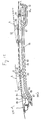
- the guide member 13 secured to the left side body 11 comprises paired upper and lower guide rails 25 and 25 as is seen from Fig. 11.
- the rails 25 and 25 have at their facing portions guide grooves 23 and 23 of generally V-shaped cross section.
- a front part of the guide member 13 is smoothly inclined downward.
- the guide member 13 comprises a horizontally extending major part and a downwardly inclined front part.
- the front and rear ends of the paired rails 25 and 25 (viz., the front and rear ends of the guide member 13) are each held by a base plate 29 and a holding plate 31 (see Fig. 13).
- these plates 29 and 31 are secured to each other by means of connecting pins 41.
- the base plate 29 and the holding plate 31 at each end of the guide member 13 hold therebetween a guide body 27 of a plastic which has a wire guide groove 27a formed therethrough.
- the base plates 29 and 29 are secured to an inner panel 33 of a rear-left wheel house of the vehicle.
- a connecting plate 35 is bolted to both the paired upper and lower rails 25 and 25 at the junction partions each being defined between the inclined front part of the guide member 13 and the horizontal major part of the same.
- the guide member 13 is equipped at its front and rear ends with first and second engaging pins P1 and P2 which are engageable with after-mentioned first and second latch members 37 and 39.
- the first engaging pin P1 has an extended part 41 by which the front base plate 29 and the front holding plate 31 are secured.
- the extended part 41 serves as a fixing pin for the plates 29 and 31.
- the second engaging pin P2 is secured to a forwardly extending part 31a of the rear holding plate 31.
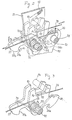
- the essential part of the side slide mechanism is housed in a housing 43 which is located beside a rear-left wheel housing of the vehicle 1.
- the housing 43 is formed at its upper part with an elongate opening 43a which extends along the axis of the vehicle 1 and at its inside wall with an opening 43b which is plugged with a lid 44.
- the afore-mentioned mounting bracket 9 of the openable roof 5 has a lower part inserted into the housing 43 through the elongate opening 43a.
- the carrier plate 21 is located within the housing 43 and secured to the lower part of the mounting bracket 9 by means of bolts 45 and nuts 46.
- the lower part of the mounting bracket 9 and the carrier plate 21 have matable bolt holes 9a and 21a respectively as is seen from Fig. 4.
- the opening 43b for the lid 44 is positioned near the bolted portion of the carrier plate 21 and an after-mentioned third detecting switch S3 for the purpose which will become apparent as the description proceeds.
- the carrier plate 21 has a base portion supported by a roller device 47 and is constantly biased by a biasing spring 49 to pivot forwardly, that is, in a counterclockwise direction in this drawing.
- the roller device 47 comprises first and second rollers 51 and 52 which run along the guide groove 23 of the lower rail 25 of the guide member 13. As is seen from Fig. 2, the first and second rollers 51 and 52 are rotatably connected through respective shafts 55 and 55 to a holding plate 53.
- the plate 53 has a front bent end 53a which serves as a stopper.
- the shaft 55 of the first roller 51 pierces the holding plate 53 and has an extended part 55a (see Fig. 6) pivotally connected to a base portion of the carrier plate 21. That is, the extended part 55a is journaled by a sub-plate 57 which is secured to the carrier plate 21 by means of rivets 59. With this, the movement of the first and second rollers 51 and 52 along the guide groove 23 is smoothly carried out without suffering undesired play.
- the stopper bent end 53a of the holding plate 53 is formed to suppress an excessive forward pivoting of the carrier plate 21.
- the carrier plate 21 is biased by a biasing spring 49 to contact with the stopper bent end 53a, so that the carrier plate 21 keeps its upright standing position during its movement along the guide member 13.
- a biasing spring 49 to contact with the stopper bent end 53a, so that the carrier plate 21 keeps its upright standing position during its movement along the guide member 13.
- roller device 47 is located at the downwardly inclined front part of the guide member 13.
- the carrier plate 21 is equipped with a stopper pin P3.
- the extended part 55a of the shaft 55 of the first roller 51 pivotally mounts thereabout first and second latch members 37 and 39 which have respective hook portions 37a and 39a projected in opposite directions.
- the hook portions 37a and 39a of the latch members 37 and 39 are formed to be latchingly engageable with the afore-mentined first and second engaging pins P1 and P2 of the guide member 13.
- the first and second latch members 37 and 39 are formed at their upper portions with identical recesses 61 and 63.
- the stopper pin P3 of the carrier plate 21 is usually received in the resesses 61 and 63 as shown in Fig. 3. During rearward movement (viz., the rightward movement in Fig.
- a left wall of the recess 61 of the first latch member 37 abuts on the stopper pin P3 and thus presses against the carrier plate 21.
- a right wall of the recess 63 of the second latch member 39 abuts on the stopper pin P3 and thus presses against the carrier plate 21.
- the hook portion 39a of the second latch member 39 is arranged behind the extended part 55a of the shaft 55 of the first roller 51, while the hook portion 37a of the first latch member 37 is arranged in front of the extended part 55a. Due to work of a biasing spring 65 disposed about the extended part 55a of the shaft 55, the first and second latch members 37 and 39 are biased in counterclockwise and clockwise directions respectively.
- the hook portion 37a of the first latch member 37 is thus brought into latching engagement with the first engaging pin P1 of the guide member 13.
- the electric motor M S serving as the drive means 17 is of a reversable type.
- the motor M S is mounted on a base plate 67 which is secured to the inner panel 33 of the rear-left wheel housing (see Fig. 19).
- a worm 69 driven by the motor M S is meshed with a worm wheel 71 which is equipped with a drive gear 77.
- the drive gear 77 is meshed with a drum gear 75 of a wire winding drum 73.
- the wire winding drum 73 is rotated about its shaft 73a in one or the other direction in response to operation of the motor M S .
- a wire cable 79 is wound about the wire winding drum 73 having both ends released therefrom.
- One end of the wire cable 79 is passed through the wire guide groove 27a of the guide body 27 and connected to a mounting pin P4 (see Figs. 2 and 3) of the first latch member 37, while, the other end of the wire cable 79 is passed through the guide groove 27a of the other guide body 27 and connected to a mounting pin P5 of the second latch member 39 (see Figs. 2 and 3).
- the mounting pins P4 and P5 on the first and second latch members 37 and 39 are located above the extended part 55a of the shaft 55 about which the first and second latch members 37 and 39 are rotatable.
- latch members 37 and 39 are pivoted upward about the shaft 55 thereby releasing the hook portions 37a and 39a thereof from the first and second engaging pins P1 and P2.
- latch member 37 (or 39) is pivoted in this manner, the left wall of the recess 61 of the first latch member 37 (or the right wall of the recess 63 of the second latch member 39) is brought into abutment with the stopper pin P3 of the carrier plate 21.
- a manual switch is mounted in a suitable portion of the vehicle 1. That is, upon manipulation of the switch, the motor M S becomes energized.
- first, second and third switches S1, S2 and S3 are mounted on the guide member 13, which control the operation of the motor M S .
- the first switch S1 is mounted on the front end of the guide member 13 and becomes OFF condition when the openable roof 5 is brought into its full close position. That is, upon full closing of the roof 5, the holding plate 53 moved with the carrier plate 21 strikes against a detecting bar S1-1 of the switch S1 thereby to cause OFF condition of the switch S1. Thus, the detecting bar S1-1 is placed on a travelling path described by the holding plate 53.
- the second switch S2 is mounted on the rear end of the guide member 13 and becomes OFF condition when the openable roof 5 is brought into its full open position. That is, upon full opening of the roof 5, the holding plate 53 moved with the carrier plate 21 strikes against a detecting bar S2-2 of the switch S2 thereby to cause OFF condition of the switch S2. Thus, the detecting bar S2-2 is placed on a travelling path described by the holding plate 53.
- the third switch S3 is mounted on the front end of the horizontal major part of the guide member 13 and becomes OFF condition when the openable roof 5 is brought into a given slight open position during its opening movement. That is, upon the openable roof 5 coming to the given slight open position, the holding plate 53 moved with the carrier plate 21 strikes against a detecting bar S3-3 of the switch S3 thereby to cause OFF condition of the switch S3. Thus, the detecting bar S3-3 is placed on a travelling path described by the holding plate 53.
- FIGs. 13 and 14 there is shown the upper slide mechanism of the openable roof control device of the invention.
- the guide member 15 is mounted on the center beam 3b of the T-bar roof construction 3 in a manner to extend along the same.
- the guide member 15 carries thereon the carrier plate 22 which is driven by the drive means 19.
- the guide member 15 comprises an outer rail 81 and an inner rail 82 which are combined to have an elongate hollow construction of a generally rectangular cross section. Thus, there is defined within the construction a guiding space 80.
- the outer rail 81 is formed with a longitudinally extending guide slot 81a. Similar to the case of the afore-mentioned side slide mechanism, a front part of the guide member 15 is smoothly inclined downward. That is, also in this upper slide mechanism, the guide member 15 comprises a horizontally extending major part and a downwardly inclined front part.
- the carrier plate 22 is of an elongate member, which is arranged perpendicular relative to the guide member 15.
- the carrier plate 22 has lateral both ends each having a mounting opening 22a.
- the carrier plate 22 is secured, by means of bolts 83 and nuts 84 incorporated with the mounting openings 22a, to a front middle part of the openable roof 5.
- the carrier plate 22 has at its middle part a runner 85 welded thereto and projected downward therefrom.
- the runner 85 extends through the guide slot 81a of the outer rail 81 into the guiding space 80 of the guide member 15 and carries two parallel rollers 87 and 87 through a shaft 89 secured thereto.
- the rollers 87 and 87 run along respective trucks defined along both sides of the guiding space 80, as shown.
- the rollers 87 and 8y run along the trucks in the same manner.
- the electric motor M U which serves as the drive means 19 is of a reversable type, which is mounted to a base plate 91 (see Fig. 14) secured to the laterally extending reinforcing beam 3a of the T-bar roof construction 3.
- a worm 92 driven by the motor M U is meshed with a worm wheel 93 which is equipped with a drive gear 96.
- the drive gear 96 is meshed with a drum gear 95 of a wire winding drum 94.
- the wire winding drum 94 is rorated about its shaft 94a in one or the other direction in response to operation of the motor M U .
- a wire cable 97 is wound about the wire winding drum 94 having both ends released therefrom.
- One end of the wire cable 97 is connected to the carrier plate 22, while, the other end of the wire cable 97 is passed through a wire guide groove 98a of a guide body 98 (see Fig. 16) and connected to the carrier plate 22.
- the guide body 98 is connected to one side of the guide member 15.
- the motor M U is controlled by the above-mentioned manual switch which is mounted in a suitable portion of the vehicle.
- first, second and third switches S′1, S′2 and S′3 are mounted on the guide member 15, which control operation of the motor M U .
- the first switch S′1 is mounted on the front end of the guide member 15 and becomes OFF condition when the openable roof 5 is brought into the full close position. That is, upon full closing of the roof 5, one of the the rollers 87 moved with the carrier plate 22 strikes against a detecting bar S′1-1 of the switch S′1 thereby to cause OFF condition of the swtich S′1. Thus, the detecting bar S′2-2 is placed on a travelling path described by the roller 87.
- the second switch S′3 is mounted on the rear end of the guide member 15 and becomes OFF condition when the openable roof 5 brought into its full open position. That is, upon full opening of the roof 5, one of the the rollers 87 moved with the carrier plate 22 strikes against a detecting bar S′2-2 of the switch S′2 thereby to cause OFF condition of the swtich S′2. Thus, the detecting bar S′2-2 is placed on a travelling path described by the roller 87.
- the third switch S′3 is mounted on a front portion of the guide member 15 and becomes OFF condition when the openable roof 5 is brought into a given slight open position during its opening movement. That is, upon the openable roof 5 coming to the given slight open position, the roller 87 moved with the carrier plate 22 strikes against a detecting bar S′3-3 of the switch S′3 thereby to cause OFF condition of the switch S′3. Thus, the detecting bar S′3-3 is placed on a travelling path described by the roller 87.
- the first, second and third switches S′1, S′2 and S′3 of the upper slide mechanism and the first, second and third switches S1, S2 and S3 of each side slide mechanism are both arranged to assume OFF conditions when the openable roof comes to the full close position, the full open position and the predetermined slight open position, respectively.
- the three third switches S3, S3 and S′3 of the side slide mechanisms and the upper slide mechanism are used for determining the positions of the carrier plates 21 and 22 where dismounting and mounting of the openable roof 5 relative to the carrier plates 21 and 22 of these mechanisms can be achieved. That is, when the openable roof 5 is moved back to the slight open position, the same stops at the position due to function of these three third switches. Thus, the roof 5 is easily dismounted from the carrier plates 21 and 22. With this, the vehicle becomes an "Open Car". When the vehicle is in the shape of the Open Car, the carrier plates 21 and 22 are held at the foremost or rest positions. Of couse, re-mounting of the roof 5 to the plates 21 and 22 is easily carried out when, by manipulation of the manual switch, the plates 21 and 22 are brought to positions corresponding to the slight open position of the openable roof 5.
- the wire cables 79 and 97 are moved to pull the carrier plates 21 and 22 rearward.
- the first latch member 37 (see Fig. 2) of the side slide mechanism is pivoted to release the first engaging pin P1 and cause the front wall of the recess 61 thereof to abut against and thus push the stopper pin P3 of the carrier plate 21.
- further movement of the wire cables 79 and 97 pulls the carrier plates 21 and 22 together with the roof 5 rearward along the downwardly inclined front parts of the guide members 13 and 15. Due to this movement, the weather strip 7 of the roof 5 is separated from the peripheral edge of the roof opening of the vehicle body.
- the wire cables 79 and 97 are moved to pull the carrier plates 21 and 22 forward.
- the second latch member 39 (see Fig. 2) is pivoted to release the second engaging pin P2 and cause the rear wall of the recess 63 thereof to abut against and thus push the stopper pin P3 of the carrier plate 21.
- further movement of the wire cables 79 and 97 pulls the carrier plates 21 and 22 together with the roof 5 toward the full close position.
- the first latch member 37 When the roof 5 comes to the full close position, the first latch member 37 is brought into latching engagement with the first engaging pin P1 and the energization of the motors M S and M U stops. Thus, the roof 5 is safely latched at the full close position, as is shown in Figs. 20 and 21.
- the roof 5 In order to dismount the roof 5 from the vehicle body 1, the roof 5 is moved to the given slight open position by manipulating the manual switch in the above-mentioned manner, and then the bolts and nuts 45 and 46 of the side slide mechanism (see Fig. 19) are disconnected and the bolts and nuts 83 and 84 of the upper slide mechanism (see Fig. 15) are disconnected.
- the disconnection of the bolts 45 and 46 is carried out by inserting a suitable tool through the opening 43b of the housing 43. With this, the vehicle becomes an "Open Car".
- the carrier plates 21 and 22 By manipulating the manual switch, the carrier plates 21 and 22 are moved to their foremost or rest positions, so that under this condition egress and ingress of passengers are not interrupted by them.
- remounting of the roof 5 to the vehicle body 1 is carried out after the carrier plates 21 and 22 are moved to the positions which correspond to the given slight open position of the roof 5.
- the openable roof control device of the present invention has the above-mentioned construction, the following advantages are expected.
- the openable roof is supported by the three slide mechanisms which are arranged on mutually spaced portions of the vehicle body, the sliding movement of the roof between the full close and full open positions is assuredly and reliably achieved without suffering a play.
- the openable roof at the full close or full open position can be assuredly latched to the vehicle body. This induces an assured sealing between contacting portions of the vehicle body and the openable roof.
Landscapes
- Engineering & Computer Science (AREA)
- Mechanical Engineering (AREA)
- Power-Operated Mechanisms For Wings (AREA)
- Lock And Its Accessories (AREA)
Applications Claiming Priority (6)
| Application Number | Priority Date | Filing Date | Title |
|---|---|---|---|
| JP62261735A JPH0647333B2 (ja) | 1987-10-19 | 1987-10-19 | 車両用開閉ルーフの開閉制御装置 |
| JP261735/87 | 1987-10-19 | ||
| JP158815/87U | 1987-10-19 | ||
| JP261736/87 | 1987-10-19 | ||
| JP15881587U JPH0634167Y2 (ja) | 1987-10-19 | 1987-10-19 | 車両用開閉ルーフの開閉制御装置 |
| JP26173687A JPH01106726A (ja) | 1987-10-19 | 1987-10-19 | 車両用開閉ルーフの開閉制御装置 |
Publications (2)
| Publication Number | Publication Date |
|---|---|
| EP0312990A2 true EP0312990A2 (fr) | 1989-04-26 |
| EP0312990A3 EP0312990A3 (fr) | 1990-11-07 |
Family
ID=27321413
Family Applications (1)
| Application Number | Title | Priority Date | Filing Date |
|---|---|---|---|
| EP19880117341 Withdrawn EP0312990A3 (fr) | 1987-10-19 | 1988-10-18 | Dispositif de contrôle pour toit amovible de véhicule automobile |
Country Status (2)
| Country | Link |
|---|---|
| US (1) | US4953910A (fr) |
| EP (1) | EP0312990A3 (fr) |
Cited By (1)
| Publication number | Priority date | Publication date | Assignee | Title |
|---|---|---|---|---|
| WO2006063557A1 (fr) * | 2004-12-16 | 2006-06-22 | Wilhelm Karmann Gmbh | Cabriolet pourvu d'une partie toit pouvant etre ouverte separement |
Families Citing this family (2)
| Publication number | Priority date | Publication date | Assignee | Title |
|---|---|---|---|---|
| CA3188886A1 (fr) * | 2020-08-28 | 2022-03-03 | Marc Cogswell | Assistance au retrait d'un toit rigide |
| CN114481732B (zh) * | 2022-02-28 | 2023-04-14 | 贵州省交通规划勘察设计研究院股份有限公司 | 能提升驾驶员安全性的高速公路避险车道 |
Family Cites Families (6)
| Publication number | Priority date | Publication date | Assignee | Title |
|---|---|---|---|---|
| GB884345A (en) * | 1959-03-25 | 1961-12-13 | Webasto Werk Baier Kg W | Improvements in and relating to rigid sliding roofs for vehicles |
| DE2647236A1 (de) * | 1976-10-20 | 1978-04-27 | Daimler Benz Ag | Kraftfahrzeug, insbesondere personenkraftwagen, mit einem verschiebbaren wagenkastenoberteilabschnitt |
| JPS5830830A (ja) * | 1981-08-13 | 1983-02-23 | Aisin Seiki Co Ltd | サンル−フ用駆動装置 |
| JPS62101528A (ja) * | 1985-10-29 | 1987-05-12 | Johnan Seisakusho Co Ltd | 自動車用開閉ル−フの回動装置 |
| JPS62157825A (ja) * | 1985-12-28 | 1987-07-13 | Aisin Seiki Co Ltd | 車輌の車室開閉装置 |
| JPS62163822A (ja) * | 1986-01-16 | 1987-07-20 | Aisin Seiki Co Ltd | 車輌の車室格納装置 |
-
1988
- 1988-10-18 US US07/260,127 patent/US4953910A/en not_active Expired - Fee Related
- 1988-10-18 EP EP19880117341 patent/EP0312990A3/fr not_active Withdrawn
Cited By (1)
| Publication number | Priority date | Publication date | Assignee | Title |
|---|---|---|---|---|
| WO2006063557A1 (fr) * | 2004-12-16 | 2006-06-22 | Wilhelm Karmann Gmbh | Cabriolet pourvu d'une partie toit pouvant etre ouverte separement |
Also Published As
| Publication number | Publication date |
|---|---|
| EP0312990A3 (fr) | 1990-11-07 |
| US4953910A (en) | 1990-09-04 |
Similar Documents
| Publication | Publication Date | Title |
|---|---|---|
| JPH0349047Y2 (fr) | ||
| EP1010558B1 (fr) | Système de porte glissante pour véhicules | |
| US6305740B1 (en) | Automotive vehicle having moveable roof panel | |
| US4647106A (en) | Lifting/sliding roof for vehicles | |
| US6481783B1 (en) | Drive mechanism for power operated slideable side door | |
| US5301987A (en) | Convertible top stack latch | |
| US4869544A (en) | Sliding doors | |
| US6174024B1 (en) | Device for actuating a lifting and sliding roof | |
| JPS6229413A (ja) | 引き戸式車輌ドア機構 | |
| EP0723887B1 (fr) | Toit ouvrant pour véhicule | |
| EP0312990A2 (fr) | Dispositif de contrôle pour toit amovible de véhicule automobile | |
| US6439655B1 (en) | Openable hatch in a fixed roof surface of motor vehicle | |
| EP0376208B1 (fr) | Structure de toît ouvrant en toile pour un véhicule automobile | |
| JPH0327000Y2 (fr) | ||
| JPH071304Y2 (ja) | サンシエード装置 | |
| JPH0235537Y2 (fr) | ||
| JPH01106725A (ja) | 車両用開閉ルーフの開閉制御装置 | |
| JPH0218114A (ja) | ドアシステム | |
| US5280992A (en) | Tilt and slide roof opening and closing device, in particular for automobile vehicles | |
| JPS6313926Y2 (fr) | ||
| JPH0420809B2 (fr) | ||
| JPH074973Y2 (ja) | 自動車のサンルーフ開閉装置 | |
| JP2551949Y2 (ja) | サンルーフの開閉装置 | |
| JPS62261527A (ja) | スライド式ル−フを有する自動車 | |
| JPH0349925Y2 (fr) |
Legal Events
| Date | Code | Title | Description |
|---|---|---|---|
| PUAI | Public reference made under article 153(3) epc to a published international application that has entered the european phase |
Free format text: ORIGINAL CODE: 0009012 |
|
| 17P | Request for examination filed |
Effective date: 19881018 |
|
| AK | Designated contracting states |
Kind code of ref document: A2 Designated state(s): DE GB |
|
| PUAL | Search report despatched |
Free format text: ORIGINAL CODE: 0009013 |
|
| AK | Designated contracting states |
Kind code of ref document: A3 Designated state(s): DE GB |
|
| 17Q | First examination report despatched |
Effective date: 19920921 |
|
| STAA | Information on the status of an ep patent application or granted ep patent |
Free format text: STATUS: THE APPLICATION IS DEEMED TO BE WITHDRAWN |
|
| 18D | Application deemed to be withdrawn |
Effective date: 19950502 |