EP0313042A2 - Procédé et appareil de traitement d'images de rayonnement et traitement d'image de rayons X - Google Patents
Procédé et appareil de traitement d'images de rayonnement et traitement d'image de rayons X Download PDFInfo
- Publication number
- EP0313042A2 EP0313042A2 EP88117483A EP88117483A EP0313042A2 EP 0313042 A2 EP0313042 A2 EP 0313042A2 EP 88117483 A EP88117483 A EP 88117483A EP 88117483 A EP88117483 A EP 88117483A EP 0313042 A2 EP0313042 A2 EP 0313042A2
- Authority
- EP
- European Patent Office
- Prior art keywords
- image
- original image
- carrying
- signal
- radiation
- Prior art date
- Legal status (The legal status is an assumption and is not a legal conclusion. Google has not performed a legal analysis and makes no representation as to the accuracy of the status listed.)
- Granted
Links
Images


Classifications
-
- H—ELECTRICITY
- H04—ELECTRIC COMMUNICATION TECHNIQUE
- H04N—PICTORIAL COMMUNICATION, e.g. TELEVISION
- H04N1/00—Scanning, transmission or reproduction of documents or the like, e.g. facsimile transmission; Details thereof
- H04N1/40—Picture signal circuits
- H04N1/409—Edge or detail enhancement; Noise or error suppression
- H04N1/4092—Edge or detail enhancement
Definitions
- This invention relates to frequency response processing for a radiation image, particularly a radiation image processing method in a radiation image recording and reproducing system for recording a radiation image on a stimulable phosphor as an intermediate medium, obtaining image signals from the radiation image, and reproducing the radiation image as a visible image on a recording medium by use of the image signals, and an apparatus for carrying out the method.
- This invention also relates to an X-ray image processing method for processing the signals representing original image densities detected from an X-ray image, which has been recorded on an original photograph by the irradiation of X-rays to an object, at the time the X-ray image is to be copied, and an apparatus for carrying out the method.
- phosphors When certain kinds of phosphors are exposed to a radiation such as X-rays, ⁇ -rays, ⁇ -rays, ⁇ -rays, cathode rays or ultraviolet rays, they store a part of the energy of the radiation. Then, when the phosphor which has been exposed to the radiation is exposed to stimulating rays such as visible light, light is emitted by the phosphor in proportion to the stored energy of the radiation.
- stimulating rays such as visible light
- a phosphor exhibiting such properties is referred to as a stimulable phosphor.
- a stimulable phosphor sheet As disclosed in U.S. Patent No. 4,258,264 and Japanese Unexamined Patent Publication No. 56(1981)-11395, it has been proposed to use a stimulable phosphor in a radiation image recording and reproducing system. Specifically, a sheet provided with a layer of the stimulable phosphor (hereinafter referred to as a stimulable phosphor sheet) is first exposed to a radiation passing through an object such as the human body to have a radiation image of the object stored thereon, and is then two-dimensionally scanned by stimulating rays such as a laser beam which cause the stimulable phosphor sheet to emit light in proportion to the stored radiation energy.
- a stimulable phosphor sheet a sheet provided with a layer of the stimulable phosphor
- the light emitted by the stimulable phosphor sheet upon stimulation thereof is photoelectrically detected by a photodetector and converted to electric image signals, and the radiation image of the object is reproduced as a visible image by use of the image signals on a recording medium such as a photographic film, a display device such as a cathode ray tube (CRT), or the like.
- a recording medium such as a photographic film
- a display device such as a cathode ray tube (CRT), or the like.
- the radiation image recording and reproducing system using a stimulable phosphor sheet is advantageous over conventional radiography using a silver halide photographic material in that the image can be recorded over a very wide range (latitude) of radiation exposure. More specifically, since the amount of light emitted upon stimulation after the radiation energy is stored on the stimulable phosphor varies over a wide range in proportion to the amount of said stored energy, it is possible to obtain an image having desirable density regardless of the amount of exposure of the stimulable phosphor sheet to the radiation, by reading out the emitted light with an appropriate read-out gain and converting it into electric signals to reproduce a visible image on a recording medium or a display device.
- the radiation dose to the human body can be decreased markedly as compared with the conventional X-ray image recording diagnosis system.
- a blur image may be stored on the stimulable phosphor sheet at the time of the image recording by making the stimulable phosphor sheet thicker or by making larger the grains of the stimulable phosphor used in the stimulable phosphor sheet.
- the image may be blurred at the time of the image read-out by increasing the beam diameter of stimulating rays used for the scanning, or the read-out image may be blurred by feeding the read-out analog image signals into an analog filter. Fine control is necessary in order to improve the graininess while deterioration of the other image quality factors such as sharpness are being minimized.
- the kind of the stimulable phosphor sheet must be increased, and the degree of freedom of the control is limited even though the kind of the stimulable phosphor sheet is increased. Also, the degree of freedom of the control is very low though the mechanism becomes complicated, and the control is possible only in the direction of flow of the sequential image signals (the direction of main scanning).
- frequency response processing may be carried out by use of FFT (fast Fourier transform), or the image may be digitally blurred by calculating a mean value of the image signals around each scanning point. With the method using FFT, the degree of freedom of the control is very high.
- the processing speed is too low to process large numbers of the image signals, and a high cost is required to increase the processing speed.
- the image is digitally blurred by use of the mean value, fine control cannot be achieved and the image is generally blurred excessivly even though the processing can be carried out quickly.
- the primary object of the present invention is to provide a radiation image processing method which improves graininess of a radiation image while deterioration of other image quality factors is being minimized, and which is carried out without an apparatus being caused to become complicated and in an operation time within a substantially allowable range, and an apparatus for carrying out the method.
- Another object of the present invention is to provide a radiation image processing method which improves the overall image quality by improving the sharpness, contrast and the like while grain noise of the radiation image is being restricted, and which is carried out without an apparatus being caused to become complicated and in an operation time within a substantially allowable range, and an apparatus for carrying out the method.
- a further object of the present invention is to provide an X-ray image processing method which improves graininess of an X-ray image while deterioration of other image quality factors is being minimized, and which is carried out without an apparatus being caused to become complicated and in an operation time within a substantially allowable range, and an apparatus for carrying out the method.
- a still further object of the present invention is to provide an X-ray image processing method which improves the overall image quality by improving the sharpness, contrast and the like while grain noise of the X-ray image is being restricted, and which is carried out without an apparatus being caused to become complicated and in an operation time within a substantially allowable range, and an apparatus for carrying out the method.
- the present invention provides a first radiation image processing method which comprises the steps of: in the course of scanning a stimulable phosphor carrying a radiation image stored thereon by stimulating rays which cause said stimulable phosphor to emit light in proportion to the stored radiation energy, obtaining an original image signal by photoelectrically detecting the light emitted by each scanning point of said stimulating rays on said stimulable phosphor, and reproducing said radiation image as a visible image on a recording medium,
- the first radiation image processing method in accordance with the present invention is carried out by a first radiation image processing apparatus in a radiation image recording and reproducing system for scanning a stimulable phosphor carrying a radiation image stored thereon by stimulating rays which cause said stimulable phosphor to emit light in proportion to the stored radiation energy, obtaining an original image signal by photoelectrically detecting the light emitted by each scanning point of said stimulating rays on said stimulable phosphor, processing the original image signal by an operation device, and reproducing said radiation image as a visible image on a recording medium by use of the processed image signal, wherein the improvement comprises constituting said operation device for:
- At least a single attenuation coefficient ⁇ l among the attenuation coefficients ⁇ k, where k 1, 2, ..., n, is adjusted to be a constant within the range of 0 ⁇ l wherein ⁇ l ⁇ 1, and the operation represented by the formula is carried out.
- the unsharp mask signal Sus.l is subtracted from Sb2 which is, by way of example, the original image signal as represented by Sb2-Sus.l in the parentheses of the second term, whereby the low spatial frequency component which the unsharp mask signal Sus.l has is subtracted from Sb2.
- Sb2-Sus.l is multiplied by the attenuation coefficient 8 satisfying the condition of 0 ⁇ l wherein ⁇ l ⁇ 1 as represented by ⁇ l(Sb2-Sus.l), and ⁇ l(Sb2-Sus.l) is subtracted from Sb1 which is, by way of example, the original image signal.
- the high spatial frequency component which Sb2-Sus.l has can be attenuated from the signal Sb1.
- the high spatial frequency component is made to coincide with grainy noise of the image and the attenuation coefficient ⁇ l is adjusted to be an appropriate value satisfying the condition of 0 ⁇ l wherein ⁇ l ⁇ 1, grainy noise of the image can be attenuated, and deterioration of other image quality factors such as sharpness can be minimized.
- the first radiation image processing apparatus for carrying out the first radiation image processing method is not complicated as compared with the radiation image processing apparatuses in the radiation image recording and reproducing system proposed by the applicant in, for example, U.S. Patent No. 4,258,264 and Japanese Unexamined Patent Publication No.
- the original image signal obtained by the photoelectric detection may be used as the image signals Sb1 and Sb2, or an image signal obtained by carrying out intermediate processing of the original image signal may be used as one or both of the image signals Sb1 and Sb2.
- Grainy noise has a wide range of spatial frequency components. Therefore, in the case where grainy noise cannot be substantially restricted by the combination of the first term with the second term of Formula (2), the same operation as the second term is carried out in the third term or the fourth term by changing the spatial frequency region from the frequency region in the second term. Also, an attenuation coefficient ⁇ m where m ⁇ l may be adjusted so that ⁇ m ⁇ 0 in the third and fourth term and, for example, an operation for emphasizing specific spatial frequency components as proposed by the applicant in U.S. Patent No. 4,315,318 may be used in combination.
- Formula (4) indicates that the spatial frequency components which grainy noise has are attenuated positively.
- the inventors of the present invention studied the properties of grainy noise and found that grainy noise can be rendered imperceptible while deterioration of other image quality factors such as sharpness is being minimized by accurately selecting the spatial frequency which is to be attenuated and the extent of attenuation of said spatial frequency, and positively restricting the spatial frequency components which grainy noise has.
- the optimal value of the attenuation coefficient ⁇ l employed for carrying out the attenuation is generally present in the range of 0 ⁇ l ⁇ 1, depending on the kind of the radiation image or the like.
- the spatial frequency components above the spatial frequency component which the unsharp mask signal Sus.l has can be attenuated, grainy noise of the radiation image can be attenuated efficiently, and deterioration of other image quality factors can be minimized.
- the apparatus for carrying out the first radiation image processing method in accordance with the present invention is not so complicated and can achieve the operation in a time within a substantially allowable range.
- the present invention also provides a second radiation image processing method which comprises the steps of: in the course of scanning a stimulable phosphor carrying a radiation image stored thereon by stimulating rays which cause said stimulable phosphor to emit light in proportion to the stored radiation energy, obtaining an original image signal by photoelectrically detecting the light emitted by each scanning point of said stimulating rays on said stimulable phosphor, and reproducing said radiation image as a visible image on a recording medium,
- the second radiation image processing method in accordance with the present invention is carried out by a second radiation image processing apparatus in a radiation image recording and reproducing system for scanning a stimulable phosphor carrying a radiation image stored thereon by stimulating rays which cause said stimulable phosphor to emit light in proportion to the stored radiation energy, obtaining an original image signal by photoelectrically detecting the light emitted by each scanning point of said stimulating rays on said stimulable phosphor, processing the original image signal by an operation device, and reproducing said radiation image as a visible image on a recording medium by use of the processed image signal, wherein the improvement comprises constituting said operation device for:
- the unsharp mask signal Sus.l is subtracted from Sb2 which is, by way of example, the original image signal as represented- by Sb2-Sus.l in the parentheses of the second term, whereby the low spatial frequency component which the unsharp mask signal Sus.l has is subtracted from Sb2.
- Sb2-Sus.l is multiplied by the attenuation coefficient ⁇ l satisfying the condition of 0 ⁇ l as represented by ⁇ l(Sb2-Sus.l), and ⁇ l(Sb2-Sus.l) is subtracted from Sb1 which is, by way of example, the original image signal.
- the high spatial frequency component which Sb2-Sus.l has can be attenuated from the signal Sb1.
- the high spatial frequency component is made to coincide with grainy noise of the image and the attenuation coefficient ⁇ l is adjusted to be an appropriate value as the variable varying within the range of 0 ⁇ l, grainy noise of the image can be attenuated, and deterioration of other image quality factors such as sharpness can be minimized in accordance with the condition of each region inside of a single image.
- the second radiation image processing apparatus for carrying out the second radiation image processing method is not complicated as compared with the radiation image processing apparatuses in the radiation image recording and reproducing system proposed by the applicant in, for example, U.S. Patent No. 4,258,264 and Japanese Unexamined Patent Publication No. 56(1981)-11395, and can achieve the operation in a time within a substantially allowable range.
- the original image signal obtained by the photoelectric detection may be used as the image signals Sb1 and Sb2, or an image signal obtained by carrying out intermediate processing of the original image signal may be used as one or both of the image signals Sb1 and Sb2.
- Grainy noise has a wide range of spatial frequency components. Therefore, in the case where grainy noise cannot be substantially restricted by the combination of the first term with the second term of Formula (6) or finer image processing is to be carried out by changing the spatial frequency region for each region inside of a single image area, the same operation as the second term is carried out in the third term or the fourth term by changing the spatial frequency region from the frequency region in the second term. Also, an attenuation coefficient ⁇ m where m ⁇ l may be adjusted so that ⁇ m ⁇ 0 in the third and fourth term and, for example, an operation for emphasizing specific spatial frequency components as proposed by the applicant in U.S. Patent No. 4,315,318 may be used in combination.
- Formula (7) indicates that the spatial frequency components which grainy noise has are attenuated positively.
- the attenuation coefficient ⁇ l for carrying out the attenuation is varied within the range of 0 ⁇ 1, it can optimize each region inside of the image for almost every image.
- various function forms may be selected in accordance with the purpose of image processing or the like.
- the attenuation coefficient ⁇ l may be adjusted to be a function of the image signals such that a portion of a low image density in the radiation image where grainy noise is comparatively perceptible is blurred by increasing the extent of the attenuation, and the extent of the attenuation is decreased for a portion of a high image density where grainy noise is comparatively imperceptible to make the detailed structure sharper.
- the attenuation coefficient ⁇ l may be varied in accordance with the object portion inside of a single image such as a bone portion, a lung portion or a heart portion in the radiation image of the chest of the human body so that image processing is carried out to be suitable for each object portion.
- the spatial frequency components above the spatial frequency component which the unsharp mask signal Sus.l has can be attenuated. Also, grainy noise of the radiation image can be attenuated efficiently, and deterioration of other image quality factors can be minimized in accordance with each region inside of the radiation image. Moreover, the apparatus for carrying out the second radiation image processing method in accordance with the present invention is not so complicated and can achieve the operation in a time within a substantially allowable range.
- the present invention further provides a third radiation image processing method which comprises the steps of: in the course of scanning a stimulable phosphor carrying a radiation image stored thereon by exposure to radiation by stimulating rays which cause said stimulable phosphor to emit light in proportion to the stored radiation energy, obtaining an original image signal by photoelectrically detecting the light emitted by each scanning point of said stimulating rays on said stimulable phosphor, and reproducing said radiation image as a visible image on a recording medium,
- the present invention also provides a fourth radiation image processing method which comprises the steps of: in the course of scanning a stimulable phosphor carrying a radiation image stored thereon by exposure to radiation by stimulating rays which cause said stimulable phosphor to emit light in proportion to the stored radiation energy, obtaining an original image signal by photoelectrically detecting the light emitted by each scanning point of said stimulating rays on said stimulable phosphor, and reproducing said radiation image as a visible image on a recording medium,
- the third radiation image processing method in accordance with the present invention is carried out by a third radiation image processing apparatus in a radiation image recording and reproducing system for scanning a stimulable phosphor carrying a radiation image stored thereon by exposure to radiation by stimulating rays which cause said stimulable phosphor to emit light in proportion to the stored radiation energy, obtaining an original image signal by photoelectrically detecting the light emitted by each scanning point of said stimulating rays on said stimulable phosphor, processing the original image signal by an operation device, and reproducing said radiation image as a visible image on a recording medium by use of the processed image signal, wherein the improvement comprises constituting said operation device for:
- the third radiation image processing apparatus for carrying out the third radiation image processing method in accordance with the present invention may be provided with a function of carrying out other operations as well as the operation corresponding to Formula (10).
- the present invention further provides a fourth radiation image processing apparatus in a radiation image recording and reproducing system for scanning a stimulable phosphor carrying a radiation image stored thereon by exposure to radiation by stimulating rays which cause said stimulable phosphor to emit light in proportion to the stored radiation energy, obtaining an original image signal by photoelectrically detecting the light emitted by each scanning point of said stimulating rays on said stimulable phosphor, processing the original image signal by an operation device, and reproducing said radiation image as a visible image on a recording medium by use of the processed image signal, wherein the improvement comprises constituting said operation device for:
- both a region of a high radiation dose and a region of a low radiation dose are present in a single radiation image in accordance with the distribution of various tissues constituting the object, a difference in thickness of the object, and the like.
- the image signals obtained by the radiation image read-out are uniformly subjected to an operation for emphasizing the contrast, the sharpness and the like by use of the method disclosed in, for example, U.S. Patent No. 4,315,318, grain noise is emphasized and the image becomes rough in the region of a low radiation dose including more grain noise even though the image quality is improved in the region of a high radiation dose originally including less grain noise.
- the coefficient ⁇ is shifted from ⁇ 0 to ⁇ >0 as the radiation dose increases in the course of carrying out image processing represented by Formula (8).
- grain noise can be reduced positively in the region of a low radiation dose including more grain noise in the radiation image, and the image quality factors such as the sharpness and the contrast can be improved positively in the region of a high radiation dose originally including less grain noise in the radiation image. Therefore, the image quality of a reproduced visible image can be improved markedly over the case where image processing is carried out uniformly for the overall image.
- the radiation dose in each region of the radiation image is approximately proportional to the light emitted by the stimulable phosphor when the stimulable phosphor is scanned by stimulating rays. Therefore, the radiation dose in each region of the radiation image can be detected by investigating the image signal obtained by photoelectrically detecting the emitted light.
- the fourth radiation image processing method in accordance with the present invention includes other operations as well as the operation represented by Formula (8).
- Formula (9) can be rewritten into the form of
- the combination Sb1+ ⁇ l(Sb2-Sus.l) of the first term with the second term becomes identical with Formula (8).
- various kinds of image processing such as various kinds of noise reducing processing and window processing for taking up only the necessary spatial frequency components are often carried out as well as the processing in accordance with the present invention. Therefore, in the course of using the fourth radiation image processing method in accordance with the present invention, the original image signal Sorg obtained by reading out the radiation image need not necessarily be used directly, and an image signal obtained by subjecting the original image signal Sorg to intermediate processing, for example, of the type as mentioned above may be used.
- the image signal obtained by intermediate processing may also be the image signal generated in the course of carrying out the fourth radiation image processing method in accordance with the present invention.
- a coefficient ⁇ m where m ⁇ l may be adjusted so that ⁇ m>0 in the third and fourth terms and, for example, an operation for emphasizing specific spatial frequency components as proposed by the applicant in U.S. Patent No. 4,315,318 may be carried out over the overall image in order to compensate the operation of the first and second terms.
- the operation time of the operation of the first and second terms of Formula (13), i.e. the operation corresponding to the operation represented by Formula (8), is markedly shortened as compared with the operation represented by Formula (12) or the like. Therefore, finer image processing can be achieved by carrying out the operation of the third and fourth terms as mentioned above by the utilization of the margin time.
- the software execution time can be shortened in the case where the function is achieved by the software, or the apparatus configuration can be simplified in the case where the function is achieved by the hardware.
- grain noise can be reduced in the region of a low radiation dose including more grain noise in the radiation image, and the image quality factors such as the sharpness and the contrast can be improved positively in the region of a high radiation dose originally including less grain noise in the radiation image.
- the image quality of the overall image can be improved.
- the apparatuses for carrying out the third and fourth radiation image processing methods in accordance with the present invention are not so complicated and can achieve the operation in a time within a substantially allowable range.
- the present invention still further provides a first X-ray image processing method which comprises the steps of: in the course of scanning an original photograph carrying an X-ray image recorded thereon, reading out an original image density at each scanning point on said original photograph, and reproducing said X-ray image as a visible image on a copy photograph or the like,
- the first X-ray image processing method in accordance with the present invention is carried out by a first X-ray image processing apparatus for processing a signal representing an original image density, which has been read out at each scanning point on an original photograph carrying an X-ray image recorded thereon by scanning said original photograph, by an operation device, and reproducing said X-ray image as a visible image on a copy photograph or the like by use of the signal representing the processed image density,
- At least a single attenuation coefficient ⁇ l among the attenuation coefficients ⁇ k, where k 1, 2, ..., n, is adjusted to be a constant within the range of 0 ⁇ l wherein ⁇ l ⁇ 1, and the operation represented by the formula is carried out.
- the unsharp mask density Dus.l is subtracted from Db2 which is, by way of example, the original image density as represented by Db2-Dus.l in the parentheses of the second term, whereby the low spatial frequency component which the unsharp mask density Dus.l has is subtracted from Db2.
- Db2-Dus.l is multiplied by the attenuation coefficient ⁇ l satisfying the condition of 0 ⁇ l wherein ⁇ l ⁇ 1 as represented by ⁇ l(Db2-Dus.l), and ⁇ l(Db2-Dus.l) is subtracted from Db1 which is, by way of example, the original image density.
- the high spatial frequency component which Db2-Dus.l has can be attenuated from the density Db1.
- the high spatial frequency component is made to coincide with grainy noise of the image and the attenuation coefficient ⁇ l is adjusted to be an appropriate value satisfying the condition of 0 ⁇ l wherein ⁇ l ⁇ 1, grainy noise of the image can be attenuated, and deterioration of other image quality factors such as sharpness can be minimized.
- the first X-ray image processing apparatus for carrying out the first X-ray image processing method is not complicated as compared with the conventional X-ray image processing apparatus, and can achieve the operation in a time within a substantially allowable range.
- Both the image densities Db1 and Db2 may be the original image density, or one or both of the image densities Db1 and Db2 may be the image density obtained by carrying out intermediate image processing of the signal representing the original image density.
- Grainy noise has a wide range of spatial frequency components. Therefore, in the case where grainy noise cannot be substantially restricted by the combination of the first term with the second term of Formula (15), the same operation as the second term is carried out in the third term or the fourth term by changing the spatial frequency region from the frequency region in the second term. Also, an attenuation coefficient ⁇ m where m ⁇ l may be adjusted so that ⁇ m ⁇ 0 in the third and fourth term and, for example, an operation for emphasizing specific spatial frequency components as proposed by the applicant in U.S. Patent No. 4,317,179 may be used in combination.
- Formula (17) indicates that the spatial frequency components which grainy noise has are attenuated positively.
- the inventors of the present invention studied the properties of grainy noise and found that grainy noise can be rendered imperceptible while deterioration of other image quality factors, such as sharpness is being minimized by accurately selecting the spatial frequency which is to be attenuated and the extent of attenuation of said spatial frequency, and positively restricting the spatial frequency components which grainy noise has.
- the optimal value of the attenuation coefficient ⁇ l employed for carrying out the attenuation is generally present in the range of 0 ⁇ l ⁇ 1, depending on the kind of the X-ray image or the like.
- the present invention also provides a second X-ray image processing method which comprises the steps of:
- the second X-ray image processing method in accordance with the present invention is carried out by a second X-ray image processing apparatus for processing a signal representing an original image density, which has been read out at each scanning point on an original photograph carrying an X-ray image recorded thereon by scanning said original photograph, by an operation device, and reproducing said X-ray image as a visible image on a copy photograph or the like by use of the signal representing the processed image density, wherein the improvement comprises constituting said operation device for:
- At least a single attenuation coefficient ⁇ l among the attenuation coefficients ⁇ k, where k 1, 2, ..., n, is adjusted to be a variable always having a value within the range of 0 ⁇ l and the operation represented by the formula is carried out.
- the unsharp mask density Dus.l is subtracted from Db2 which is, by way of example, the original image density as represented by Db2-Dus.l in the parentheses of the second term, whereby the low spatial frequency component which the unsharp mask density Dus.l has is subtracted from Db2.
- Db2-Dus.l is multiplied by the attenuation coefficient ⁇ l satisfying the condition of 0 ⁇ l as represented by ⁇ l(Db2-Dus.l), and ⁇ l(Db2-Dus.l) is subtracted from Db1 which is, by way of example, the original image density.
- the high spatial frequency component which Db2-Dus.l has can be attenuated from the density Db1.
- the high spatial frequency component is made to coincide with grainy noise of the image and the attenuation coefficient ⁇ l is adjusted to be an appropriate value as the variable varying within the range of 0 ⁇ l, grainy noise of the image can be attenuated, and deterioration of other image quality factors such as sharpness can be minimized in accordance with the condition of each region inside of a single image.
- the second X-ray image processing apparatus for carrying out the second X-ray image processing method is not complicated as compared with the conventional X-ray image processing apparatus, and can achieve the operation in a time within a substantially allowable range.
- Both the image densities Db1 and Db2 may be the original image density, or one or both of the image densities Db1 and Db2 may be the image density obtained by carrying out intermediate image processing of the signal representing the original image density.
- Grainy noise has a wide range of spatial frequency components. Therefore, in the case where grainy noise cannot be substantially restricted by the combination of the first term with the second term of Formula (19) or finer image processing is to be carried out by changing the spatial frequency region for each region inside of a single image area, the same operation as the second term is carried out in the third term or the fourth term by changing the spatial frequency region from the frequency region in the second term. Also, an attenuation coefficient ⁇ m where m ⁇ l may be adjusted so that ⁇ m ⁇ 0 in the third and fourth term and, for example, an operation for emphasizing specific spatial frequency components as proposed by the applicant in U.S. Patent No. 4,317,179 may be used in combination.
- Formula (20) indicates that the spatial frequency components which grainy noise has are attenuated positively.
- the attenuation coefficient ⁇ l for carrying out the attenuation is varied within the range of 0 ⁇ 1, it can optimize each region inside of the image for almost every image.
- various function forms may be selected in accordance with the purpose of image processing or the like.
- the attenuation coefficient ⁇ l may be adjusted to be a function of the image signals such that a portion of a low image density in the X-ray image where grainy noise is comparatively perceptible is blurred by increasing the extent of the attenuation, and the extent of the attenuation is decreased for a portion of a high image density where grainy noise is comparatively imperceptible to make the detailed structure sharper.
- the attenuation coefficient ⁇ l may be varied in accordance with the object portion inside of a single image such as a bone portion a lung portion or a heart portion in the X-ray image of the chest of the human body so that image processing is carried out to be suitable for each object portion.
- grainy noise of the X-ray image can be attenuated efficiently, and deterioration of other image quality factors can be minimized in- accordance with each region inside of the X-ray image.
- the apparatus for carrying out the second X-ray image processing method in accordance with the present invention is not so complicated and can achieve the operation in a time within a substantially allowable range.
- the present invention further provides a third X-ray image processing method which comprises the steps of: in the course of scanning an original photograph carrying an X-ray image recorded thereon and obtained by exposing a photographic film to X-rays, reading out an original image density at each scanning point on said original photograph, and reproducing said X-ray image as a visible image on a copy photograph or the like,
- the present invention also provides a fourth X-ray image processing method which comprises the steps of: in the course of scanning an original photograph carrying an X-ray image recorded thereon and obtained by exposing a photographic film to X-rays, reading out an original image density at each scanning point on said original photograph, and reproducing said X-ray image as a visible image on a copy photograph or the like,
- the third X-ray image processing method in accordance with the present invention is carried out by a third X-ray image processing apparatus for processing a signal representing an original image density, which has been read out at each scanning point on an original photograph carrying an X-ray image recorded thereon obtained by exposure of a photographic film to X-rays by scanning said original photograph, by an operation device, and reproducing said X-ray image as a visible image on a copy photograph or the like by use of the signal representing the processed image density, wherein the improvement comprises constituting said operation device for:
- the third X-ray image processing apparatus for carrying out the third X-ray image processing method in accordance with the present invention may be provided with a function of carrying out other operations as well as the operation corresponding to Formula (23).
- the present invention further provides a fourth X-ray image processing apparatus for processing a signal representing an original image density, which has been read out at each scanning point on an original photograph carrying an X-ray image recorded thereon obtained by exposure of a photographic film to X-rays by scanning said original photograph, by an operation device, and reproducing said X-ray image as a visible image on a copy photograph or the like by use of the signal representing the processed image density, wherein the improvement comprises constituting said operation device for:
- both a region of a high X-ray dose and a region of a low X-ray dose are present in a single X-ray image in accordance with the distribution of various tissues constituting the object, a difference in thickness of the object, and the like.
- the signals representing the image densities obtained by the X-ray image read-out are uniformly subjected to an operation for emphasizing the contrast, the sharpness and the like by use of the method disclosed in, for example, U.S. Patent No. 4,317,179, grain noise is emphasized and the image becomes rough in the region of a low X-ray dose including more grain noise even though the image quality is improved in the region of a high X-ray dose originally including less grain noise.
- the coefficient ⁇ is shifted from ⁇ 0 to ⁇ >0 as the X-ray dose increases in the course of carrying out image processing represented by Formula (21).
- grain noise can be reduced positively in the region of a low X-ray dose including more grain noise in the X-ray image, and the image quality factors such as the sharpness and the contrast can be improved positively in the region of a high X-ray dose originally including less grain noise in the X-ray image. Therefore, the image quality of a reproduced visible image can be improved markedly over the case where image processing is carried out uniformly for the overall image.
- the X-ray dose in each region of the X-ray image can be detected by investigating the signal representing the original image density obtained by scanning and reading out the original photograph.
- the fourth X-ray image processing method in accordance with the present invention includes other operations as well as the operation represented by Formula (21).
- Formula (22) can be rewritten into the form of
- the original image density Dorg obtained by reading out the X-ray image need not necessarily be used directly, ahd an image density obtained by subjecting the signal representing the original image density Dorg to intermediate processing, for example, of the type as mentioned above may be used. Also, in this case, nearly the same effects as Formula (21) can be obtained, and the operation can be combined efficiently with other operation processing.
- the image density obtained by intermediate processing may also be the image density generated in the course of carrying out the fourth X-ray image processing method in accordance with the present invention.
- a coefficient Bm where m ⁇ l may be adjusted so that ⁇ m>0 in the third and fourth terms and, for example, an operation for emphasizing specific spatial frequency components as proposed by the applicant in U.S. Patent No. 4,317,179 may be carried out over the overall image in order to compensate the operation of the first and second terms.
- the operation time of the operation of the first and second terms of Formula (26), i.e. the operation corresponding to the operation represented by Formula (21), is markedly shortened as compared with the operation represented by Formula (25) or the like. Therefore, finer image processing can be achieved by carrying out the operation of the third and fourth terms as mentioned above by the utilization of the margin time.
- the software execution time can be shortened in the case where the function is achieved by the software, or the apparatus configuration can be simplified in the case where the function is achieved by the hardware.
- grain noise can be reduced in the region of a low X-ray dose including more grain noise in the X-ray image, and the image quality factors such as the sharpness and the contrast can be improved positively in the region of a high X-ray dose originally including less grain noise in the X-ray image.
- the image quality of the overall image can be improved.
- the apparatuses for carrying out the third and fourth X-ray image processing methods in accordance with the present invention are not so complicated and can achieve the operation in a time within a substantially allowable range.
- a stimulable phosphor sheet 1 carrying a radiation image of an object stored thereon is conveyed in a sub-scanning direction as indicated by the arrow Y by a sheet conveyance means 3 constituted by an endless belt or the like operated by a motor 2.
- stimulating rays 5 produced by a laser beam source 4 are reflected and deflected by a rotating polygon mirror 6 quickly rotated by a motor 13 in the direction as indicated by the arrow, and pass through a converging lens 7 constituted by a f ⁇ lens or the like.
- the optical path of the stimulating rays 5 is then changed by a mirror 8, and the stimulating rays 5 impinge upon the stimulable phosphor sheet 1 and scan it in a main scanning direction as indicated by the arrow X approximately normal to the subscanning direction as indicated by the arrow Y.
- the exposed portion of the stimulable phosphor sheet 1 emits light 9 in an optical amount proportional to the stored radiation energy.
- the emitted light 9 is guided by a light guide member 10, and photoelectrically detected by a photomultiplier 11 as a photodetector.
- the light guide member 10 is made by the forming of a light guiding material such as an acrylic plate, and has a linear light input face 10a positioned to extend along the main scanning line on the stimulable phosphor sheet 1, and a ring-shaped light output face 10b closely contacted with a light receiving face of the photomultiplier 11.
- the emitted light 9 entering the light guide member 10 from its light input face 10a is guided through total reflection inside of the light guide member 10, emanates from the light output face 10b, and is received by the photomultiplier 11. In this manner, the amount of the emitted light 9 carrying the radiation image is detected by the photomultiplier 11.
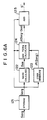
- An analog output signal S generated by the photomultiplier 11 is amplified by an amplifier 16, and digitized by an A/D converter 17 with a predetermined scale factor into an original image signal Sorg.
- the digital original image signal Sorg thus obtained is fed to an operation device 18.
- the operation device 18 calculates unsharp mask signals by averaging the image signals within a predetermined range surrounding each scanning point.
- Operation processing represented by Formula (28) indicates that spatial frequency components above the spatial frequency component which the unsharp mask signal Sus.l has are attenuated positively. Image graininess can be improved apparently and deterioration of other image quality factors such as sharpness can be minimized by accurately selecting the spatial frequency components which are to be attenuated and the extent of attenuation of the spatial frequency components.
- the image signal S′ obtained by carrying out operation processing in the operation device 18 is stored in a memory 19, and used for reproducing and displaying the radiation image on an image display device 20.
- Figures 3A, 3B and 3C show different configurations of the operation device 18 shown in Figure 2.
- the original image signal Sorg is fed to a storage means 21 from the left side and stored therein.
- the original image signal Sorg stored in the storage means 21 is directly fed to a subtraction means 24 as will be described later, and fed in parallel to n number of unsharp mask signal calculating means 22a, 22b, ..., 22n including the first unsharp mask signal calculating means 22a.
- the unsharp mask signal calculating means 22a, 22b, ..., 22n calculate unsharp mask signals Sus.1, Sus.2, ..., Sus.n respectively by averaging the image signals at N1 ⁇ N1 number of scanning points, N1 ⁇ N2 number of scanning points, ..., Nn ⁇ Nn number of scanning points around each scanning point.
- the unsharp mask signals Sus.1, Sus.2, ..., Sus.n are respectively fed to n number of attenuation term calculating means 23a, 23b, ..., 23n including the first attenuation term calculating means 23a, which calculate attenuation terms ⁇ 1(Sorg-Sus.1), ⁇ 2(Sorg-Sus.2), ..., ⁇ n(Sorg-Sus.n) respectively.
- These attenuation terms and the original image signal Sorg are fed to the subtraction means 24 which calculates as represented by a formula to obtain the operation-processed image signal S′.
- Figure 3B shows an example of the configuration of the operation device 18 different from the configuration shown in Figure 3A.
- similar elements are numbered with the same reference numerals with respect to Figure 3A.
- an unsharp mask signal calculatin- means 22′ calculates a mean value of the signals at 3 ⁇ 3 scanning points around each scanning point, and then calculates a mean value of the mean values thus obtained.
- the unsharp mask signal calculating means 22′ calculates mean values of the signals at 9 ⁇ 9 scanning points, 15 ⁇ 15 scanning points and so on, thereby to obtain the unsharp mask signals corresponding to the attenuation term calculating means 23a, 23b, ..., 23n, and sends the unsharp small signals to the attenuation term calculating means 23a, 23b, ..., 23n.
- the unsharp mask signals can be calculated efficiently.
- Figure 3C shows a further example of the configuration of the operation device 18 shown in Figure 2.
- the original image signal Sorg is temporarily stored in a storage means 21 ⁇ and then sent to an unsharp mask signal calculating means 22 ⁇ .
- the unsharp mask signal calculating means 22 ⁇ calculates the unsharp mask signal Sus.1 corresponding to the attenuation coefficient ⁇ 1 on the basis of the original image signal Sorg.
- the unsharp mask signal Sus.1 is sent to an attenuation term calculating means 23 ⁇ which calculates ⁇ 1(Sorg-Sus.1) and sends the calculated value to a subtraction means 24 ⁇ .
- the image signal S1 thus obtained is fed back to the storage means 21 ⁇ and stored instead of the original image signal Sorg which has been stored in the storage means 21 ⁇ .
- the image signal S1 is sent to the unsharp mask signal calculating means 22 ⁇ , and the unsharp mask signal Sus.2 corresponding to the attenuation coefficient ⁇ 2 is then calculated on the basis of the image signal S1.
- the unsharp mask signal Sus.2 is sent to the attenuation term calculating means 23 ⁇ which calculates as represented by ⁇ 2(S1-Sus.2).
- Grainy noise can be attenuated efficiently while deterioration of image quality factors such as the sharpness is being minimized also by calculating the unsharp mask signals Sus.1, Sus.2, ..., Sus.n by use of the intermediate-processed image signals S1, S2, ..., Sn-1 and calculating as represented by Formula (30) in the manner as mentioned above.
- the same image signal Sn-1 is used as the image signals Sb1 and Sb2 in Formula (27).
- the image signals Sb1 and Sb2 may be different from each other.
- the original image signal Sorg may be directly fed also to the attenuation term calculating means 23 ⁇ and stored therein, and calculations expressed as may be carried out in the attenuation term calculating means 23 ⁇ by use of the original image signal Sorg alone, instead of using the image signals S1, S2, ..., Sn-1 obtained by intermediate processing.
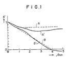
- the results of calculations are shown with respect to the spatial frequency region.
- the horizontal axis indicates the spatial frequency
- the vertical axis indicates the values relative to the direct current component taken as 1.
- S′ signals obtained by Fourier transformation of the operation-processed image signals S′ and indicated in terms of the spatial frequency region are expressed also as S′.
- the graph A is an ideal one indicating the spatial frequency characteristics suitable for restricting grainy noise of a radiation image and minimizing deterioration of other image quality factors such as the sharpness.
- the results of the calculation are indicated in terms of the spatial frequency region.
- the graph A′ is substantially approximate to the graph A.
- the graph B is an ideal one indicating the spatial frequency characteristics suitable for another radiation image.
- the results of the calculation are indicated in terms of the spatial frequency region.
- the graph B′ is substantially approximate to the graph B.
- the radiation images are classified in accordance with the kind of the object, the intensity of radiation irradiated to the object, and the like, and operation processing is carried out in accordance with the aforesaid method by selecting the method of calculation of the unsharp mask signal and selecting the value of the attenuation coefficient to be suitable for each radiation image, a reproduced visible image wherein grainy noise of the radiation image is attenuated efficiently and deterioration of other image quality factors such as the sharpness is minimized can be obtained.
- the digital original image signal Sorg obtained by the A/D converter 17 in the same manner as mentioned above is fed to the operation device 18.
- the operation device 18 calculates unsharp mask signals by averaging the image signals within a predetermined range surrounding each scanning point.
- Operation processing represented by Formula (35) indicates that spatial frequency components above the spatial frequency component which the unsharp mask signal Sus.l has are attenuated positively. Image graininess can be improved apparently and deterioration of other image quality factors such as sharpness can be minimized by accurately selecting the spatial frequency components which are to be attenuated and the extent of attenuation of the spatial frequency components.
- the image signal S′ obtained by carrying out operation processing in the operation device 18 is stored in the memory 19, and used for reproducing and displaying the radiation image on the image display device 20.
- the operation device 18 may be constituted in the same manner as shown in Figures 3A, 3B and 3C.
- Figure 4 is a graph showing an example of the function of the attenuation coefficient ⁇ l with the image signal being the variable.
- the graph shown in Figure 4 is a mere example, and a suitable function form of the attenuation coefficient ⁇ l is selected in accordance with the kind of the radiation image, the purpose of image processing and the like.
- the attenuation coefficient ⁇ l may vary in a curve form with respect to the image signal.
- the intensity of radiation irradiated to the object, and the like is carried out in accordance with the aforesaid method by selecting the method of calculation of the unsharp mask signal and selecting the value of the attenuation coefficient to be suitable for each radiation image, a reproduced visible image wherein grainy noise of the radiation image is attenuated efficiently in accordance with each region in the image and deterioration of other image quality factors such as the sharpness is minimized can be obtained.
- the digital original image signal Sorg obtained by the A/D converter 17 in the same manner as mentioned above is fed to the operation device 18.
- the original image signal Sorg is proportional to the dose of radiation irradiated to the stimulable phosphor sheet 1.
- the operation device 18 calculates an unsharp mask signal Sus by averaging the image signals within a predetermined range surrounding each scanning point.
- the coefficient ⁇ is adjusted as a function of the original image signal Sorg so that ⁇ 0 when the level of the original image signal Sorg is low and ⁇ >0 when the level of the original image signal Sorg is high.
- the operation device 18 may be constituted for:
- the image signal S′ thus obtained by carrying out operation processing in the operation device 18 is stored in the memory 19, and used for reproducing and displaying the radiation image on the image display device 20.
- Figures 5A, 5B and 5C are graphs showing examples of the functions of the coefficient ⁇ wherein the dose of radiation irradiated to the stimulable phosphor sheet 1 shown in Figure 2 is employed as a variable.
- the original image signal Sorg is read out to be proportional to the radiation dose. Therefore, the radiation dose plotted on the horizontal axis may be replaced by the original image signal Sorg.
- Figure 5B shows the example wherein the coefficient ⁇ is increased monotonously as the level of the image signal becomes higher.
- the graphs shown in Figures 5A, 5B and 5C are mere examples, and the function form may be selected appropriately from various forms in accordance with the kind of the object or the like insofar as ⁇ 0 in the region where the level of the image signal is low (the radiation dose is low) and ⁇ >0 in the region where the level of the image signal is high (the radiation dose is high). Also, experiments carried out by the inventors revealed that, though the function form of ⁇ differs in accordance with the kind of the object or the like, the coefficient ⁇ need not generally be adjusted so that ⁇ -1, and substantially appropriate image processing can be achieved in the range of -1 ⁇ .
- Figures 6A, 6B and 6C show examples of the configurations of the operation device 18 shown in Figure 2 for carrying out the third and fourth radiation image processing methods in accordance with the present invention.
- the original image signal Sorg is fed to a storage means 121 from the left side and stored therein.
- the original image signal Sorg stored in the storage means 121 is fed to an unsharp mask signal calculating means 122, a coefficient generating means 123, an addition term calculating means 124, and an addition means 125.
- the unsharp mask signal calculating means 122 calculates the unsharp mask signal Sus by averaging the image signals at N ⁇ N scanning points around each scanning point on the basis of the original image signal Sorg.
- the unsharp mask signal Sus thus calculated is fed to the addition term calculating means 124 as will be described later.
- the coefficient generating means 123 stores a table specifying the correspondence between the original image signal Sorg and the coefficient ⁇ .
- the coefficient generating means 123 generates the coefficient ⁇ corresponding to each scanning point in accordance with the value of the fed original image signal Sorg at each scanning point, and feeds the coefficient ⁇ to the addition term calculating means 124.
- the addition term calculating means 124 calculates ⁇ (Sorg-Sus) for each scanning point on the basis of the fed original image signal Sorg, the unsharp mask signal Sus and the coefficient ⁇ , and feeds out the calculated value.
- Figure 6B shows another example of the configuration of the operation device 18 shown in Figure 2.
- the original image signal Sorg is fed to a storage means 121′ from the left side and stored therein.
- the original image signal Sorg stored in the storage means 121′ is fed to n number of unsharp mask signal calculating means 122a′, 122b′, ..., 122n′, n number of coefficient generating means 123a′, 123b′, ..., 123n′, n number of addition term calculating means 124a′, 124b′, ..., 124n′, and an addition means 125′.
- n number of the unsharp mask signal calculating means 122a′, 122b′, ..., 122n′ including the first unsharp mask signal calculating means 122a′ calculate unsharp mask signals Sus.1, Sus.2, ..., Sus.n respectively by averaging the image signals at N1 ⁇ N1 number of scanning points, N2 ⁇ N2 number of scanning points, ..., Nn ⁇ Nn number of scanning points around each scanning point.
- the unsharp mask signals Sus.1, Sus.2, ..., Sus.n are respectively fed to n number of the addition term calculating means 124a′, 124b′, ..., 124n′ including the first addition term calculating means 124a′.
- n number of the coefficient generating means 123a′, 123b′, ..., 123n′ including the first coefficient generating means 123a′ store tables specifying the correspondence between the original image signal Sorg and the coefficients ⁇ 1, ⁇ 2, ... ⁇ n, corresponding to n number of the unsharp mask signals Sus.1, Sus.2, ..., Sus.n.
- the coefficient generating means 123a′, 123b′, ..., 123n′ generate the coefficients ⁇ 1, ⁇ 2, ..., ⁇ n corresponding to each scanning point in accordance with the value of the fed original image signal Sorg at each scanning point, and feed the generated coefficients respectively to n number of the addition term calculating means 124a′, 124b′, ..., 124n′ including the first addition term calculating means 124a′.
- n number of the addition term calculating means 124a′, 124b′, ..., 124n′ including the first addition term calculating means 124a′ calculate ⁇ 1(Sorg-Sus.1), ⁇ 2(Sorg-Sus.2), ..., ⁇ n(Sorg-Sus.n) respectively on the basis of the fed original image signal Sorg, the corresponding unsharp mask signals Sus.1, Sus.2, ..., Sus.n, and the corresponding coefficients ⁇ 1, ⁇ 2, ... ⁇ n.
- Figure. 6C shows a further example of the configuration of the operation device 18 shown in Figure 2.
- the original image signal Sorg is fed to a storage means 121 ⁇ from the left side and stored therein.
- the original image signal Sorg stored in the storage means 121 ⁇ is fed to an unsharp mask signal calculating means 122 ⁇ , a coefficient generating means 123 ⁇ , an addition term calculating means 124 ⁇ , and an addition means 125 ⁇ .
- the unsharp mask signal calculating means 122 ⁇ calculates the unsharp mask signal Sus.1 by averaging the image signals at N1 ⁇ N1 scanning points around each scanning point on the basis of the original image signal Sorg.
- the unsharp mask signal Sus.1 thus calculated is fed to the addition term calculating means 124 ⁇ .
- the coefficient generating means 123 ⁇ stores tables specifying the correspondence between the fed image signal and the coefficients ⁇ 1, ⁇ 2, ..., ⁇ n.
- the coefficient generating means 123 ⁇ refers to the table specifying the correspondence between the fed original image signal Sorg and the coefficient ⁇ 1, generates the coefficient ⁇ 1 corresponding to each scanning point in accordance with the value of the fed original image signal Sorg at each scanning point, and feeds the coefficient ⁇ 1 to the addition term calculating means 124 ⁇ .
- the addition term calculating means 124 ⁇ calculates ⁇ 1(Sorg-Sus.1) for each scanning point on the basis of the fed original image signal Sorg, the unsharp mask signal Sus.1 and the coefficient ⁇ 1, and feeds out the calculated value.
- the image signal S1 thus obtained is fed back to the storage means 121 ⁇ and stored instead of the original image signal Sorg which has been stored in the storage means 121 ⁇ .
- the image signal S1 is sent to the unsharp mask signal calculating means 122 ⁇ , the coefficient generating means 123 ⁇ and the addition term calculating means 124 ⁇ .
- the unsharp mask signal calculating means 122 ⁇ then calculates the unsharp mask signal Sus.2 on the basis of the image signal S1 by averaging the image signals at N2 ⁇ N2 scanning points around each scanning point.
- the coefficient generating means 123 ⁇ refers to the table specifying the correspondence between the image signal S1 and the coefficient ⁇ 2, generates the coefficient ⁇ 2 corresponding to each scanning point in accordance with the value of the fed image signal S1 at each scanning point, and feeds the coefficient ⁇ 2 to the addition term calculating means 124 ⁇ .
- Grain noise can be attenuated efficiently in the region where the radiation dose is low and grain noise is perceptible, and the image quality factors such as the sharpness and the contrast can be improved positively in the region where the radiation dose is high and grain noise is originally imperceptible also by calculating the unsharp mask signals Sus.1, Sus.2, ..., Sus.n by use of the intermediate-processed image signals S1, S2, ..., Sn-1 and calculating as represented by Formula (40) in the manner as mentioned above.
- the same image signal Sn-1 is used as the image signals Sb1 and Sb2 in Formula (37).
- the image signals Sb1 and Sb2 may be different from each other.
- the fed original image signal Sorg may be stored in the addition term calculating means 124 ⁇ , and calculations expressed as may be carried out in the addition term calculating means 124 ⁇ by use of the original image signal Sorg alone, instead. of using the image signals S1, S2, ..., Sn-1 obtained by intermediate processing.
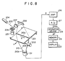
- an original photograph 201 carrying an X-ray image of an object recorded thereon is conveyed in a sub-scanning direction as indicated by the arrow Y by a photograph conveyance means 203 operated by a motor 202.
- reading light 205 produced by a laser beam source 204 is reflected and deflected by a rotating polygon mirror 206 quickly rotated by a motor 213 in the direction as indicated by the arrow, and passes through a converging lens 207 constituted by a f ⁇ lens or the like.
- the optical path of the reading light 205 is then changed by a mirror 208, and the reading light 205 impinges upon the original photograph 201 and scans it in a main scanning direction as indicated by the arrow X approximately normal to the sub-scanning direction as indicated by the arrow Y.
- the reading light 205 passes through the original photograph 201 and is intensity-modulated by the density (original image density) of the X-ray image recorded on the original photograph 201.
- the reading light 205 passing through the original photograph 201 is guided by a light guide member 210, and photoelectrically detected by a photomultiplier. 211 as a photodetector.
- the light guide member 210 is made by the forming of a light guiding material such as an acrylic plate, and has a linear light input face 210a positioned to extend along the main scanning line on the original photograph 201, and a ring-shaped light output face 210b closely contacted with a light receiving face of the photomultiplier 211.
- the reading light 205 entering the light guide member 210 from its light input face 210a is guided through total reflection inside of the light guide member 210, emanates from the light output face 210b, and is received by the photomultiplier 211. In this manner, the amount of the reading light 205 carrying the X-ray image is detected by the photomultiplier 211.
- An analog output signal D generated by the photomultiplier 211 is amplified by an amplifier 216, and digitized by an A/D converter 217 with a predetermined scale factor into an original image density Dorg.
- the digital signal representing the original image density Dorg thus obtained is fed to an operation device 218.
- the operation device 218 calculates densities of unsharp masks by averaging the image densities within a predetermined range surrounding each scanning point.
- Dorg is used for denoting the image density and denoting the signal representing the image density.
- Operation processing represented by Formula (43) indicates that spatial frequency components above the spatial frequency component which the density Dus.l of the unsharp mask has are attenuated positively. Image graininess can be improved apparently and deterioration of other image quality factors such as sharpness can be minimized by accurately selecting the spatial frequency components which are to be attenuated and the extent of attenuation of the spatial frequency components.
- the image density D′ obtained by carrying out operation processing in the operation device 218 is stored in a memory 219, and the X-ray image is reproduced and displayed on an image display device 220 by use of the signal representing the image density D′.
- Figures 9A, 9B and 9C show different configurations of the operation device 218 shown in Figure 8.
- the signal representing the original image density Dorg is fed to a storage means 221 from the left side and stored therein.
- the signal representing the original image density Dorg stored in the storage means 221 is directly fed to a subtraction means 224 as will be described later, and fed in parallel to n number of unsharp mask density calculating means 222a, 222b, ..., 222n including the first unsharp mask density calculating means 222a for calculating the density of the first unsharp mask.
- the unsharp mask density calculating means 222a, 222b, ..., 222n calculate unsharp mask densities Dus.1, Dus.2, ..., Dus.n respectively by averaging the image densities at N1 ⁇ N1 number of scanning points, N2 ⁇ N2 number of scanning points, ..., Nn ⁇ Nn number of scanning points around each scanning point.
- the unsharp mask densities Dus.1, Dus.2, ..., Dus.n are respectively fed to n number of attenuation term calculating means 223a, 223b, ..., 223n including the first attenuation term calculating means 223a, which calculate attenuation terms ⁇ 1(Dorg-Dus.1), ⁇ 2(Dorg-Dus.2), ..., ⁇ n(Dorg-Dus.n) respectively.
- These attenuation terms and the original image density Dorg are fed to the subtraction means 224 which calculates as represented by a formula to obtain the operation-processed image density D′.
- Figure 9B shows an example of the configuration of the operation device 218 different from the configuration shown in Figure 9A.
- similar elements are numbered with the same reference numerals with respect to Figure 9A.
- an unsharp mask density calculating means 222′ calculates a mean value of the densities at 3 ⁇ 3 scanning points around each scanning point, and then calculates a mean value of the mean values thus obtained.
- the unsharp mask density calculating means 22′ calculates mean values of the densities at 9 ⁇ 9 scanning points, 15 ⁇ 15 scanning points and so on, thereby to obtain the densities of the unsharp masks corresponding to the attenuation term calculating means 223a, 223b, ..., 223n, and sends the unsharp mask densities to the attenuation term calculating means 223a, 223b, ..., 223n.
- the densities of the unsharp masks can be calculated efficiently.
- Figure 9C shows a further example of the configuration of the operation device 218 shown in Figure 8.
- the signal representing the original image density Dorg is temporarily stored in a storage means 221 ⁇ and then sent to an unsharp mask density calculating means 222 ⁇ .
- the unsharp mask density calculating means 222 ⁇ calculates the density Dus.1 of the unsharp mask corresponding to the attenuation coefficient ⁇ 1 on the basis of the original image density Dorg.
- the signal representing the unsharp mask density Dus.1 is sent to an attenuation term calculating means 223 ⁇ which calculates ⁇ 1(Dorg-Dus.1) and sends the calculated value to a subtraction means 224 ⁇ .
- the signal representing the image density D1 thus obtained is fed back to the storage means 221 ⁇ and stored instead of the original image density Dorg which has been stored in the storage means 221 ⁇ .
- the signal representing the image density D1 is sent to the unsharp mask density calculating means 222 ⁇ , and the density Dus.2 of the unsharp mask corresponding to the attenuation coefficient ⁇ 2 is then calculated on the basis of the image density D1.
- the signal representing the unsharp mask density Dus.2 is sent to the attenuation term calculating means 223 ⁇ which calculates as represented by ⁇ 2(D1-Dus.2).
- Grainy noise can be attenuated efficiently while deterioration of image quality factors such as the sharpness is being minimized also by calculating the unsharp mask densities Dus.1, Dus.2, ..., Dus.n by use of the intermediate-processed image densities D1, D2, ..., Dn-1 and calculating as represented by Formula (45) in the manner as mentioned above.
- the same image density Dn-1 is used as the image densities Db1 and Db2 in Formula (42).
- the image densities Db1 and Db2 may be different from each other.
- the signal representing the original image density Dorg may be directly fed also to the attenuation term calculating means 223 ⁇ and stored therein, and calculations expressed as may be carried out in the attenuation term calculating means 223 ⁇ by use of the original image density Dorg alone, instead of using the image densities D1, D2, ..., Dn-1 obtained by intermediate processing.
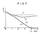
- the results of calculations are shown with respect to the spatial frequency region.
- the horizontal axis indicates the spatial frequency
- the vertical axis indicates the values relative to the direct current component taken as 1.
- signals obtained by Fourier transformation of the signals representing the operation-processed image densities D′ and indicated in terms of the spatial frequency region are expressed also as D′.
- the graph A is an ideal one indicating the spatial frequency characteristics suitable for restricting grainy noise of an X-ray image and minimizing deterioration of other image quality factors such as the sharpness.
- the results of the calculation are indicated in terms of the spatial frequency region.
- the graph A′ is substantially approximate to the graph A.
- the graph B is an ideal one indicating the spatial frequency characteristics suitable for another X-ray image.
- the results of the calculation are indicated in terms of the spatial frequency region.
- the graph B′ is substantially approximate to the graph B.
- the X-ray images are classified in accordance with the kind of the object, the intensity of X-rays irradiated to the object, and the like, and operation processing is carried out in accordance with the aforesaid method by selecting the method of calculation of the density of the unsharp mask and selecting the value of the attenuation coefficient to be suitable for each X-ray image, a reproduced visible image wherein grainy noise of the X-ray image is attenuated efficiently and deterioration of other image quality factors such as the sharpness is minimized can be obtained.
- the digital signal representing the original image density Dorg obtained by the A/D converter 217 in the same manner as mentioned above is fed to the operation device 218.
- the operation device 218 calculates densities of unsharp masks by averaging the image densities within a predetermined range surrounding each scanning point.
- Operation processing represented by Formula (50) indicates that spatial- frequency components above the spatial frequency component which the density Dus.l of the unsharp mask has are attenuated positively. Image graininess can be improved apparently and deterioration of other image quality factors such as sharpness can be minimized by accurately selecting the spatial frequency components which are to be attenuated and the extent of attenuation of the spatial frequency components.
- the image density D′ obtained by carrying out operation processing in the operation device 218 is stored in the memory 219, the X-ray image is reproduced and displayed on the image display device 220 by use of the signal representing the image density D′.
- the operation device 218 may be constituted in the same manner as shown in Figures 9A, 9B and 9C.
- Figure 10 is a graph showing an example of the function of the attenuation coefficient ⁇ l with the image density being the variable.
- the graph shown in Figure 10 is a mere example, and a suitable function form of the attenuation coefficient ⁇ l is selected in accordance with the kind of the X-ray image, the purpose of image processing and the like.
- the attenuation coefficient ⁇ l may vary in a curve form with respect to the image density.
- the intensity of X-rays irradiated to the object, and the like, and operation processing is carried out in accordance with the aforesaid method by selecting the method of calculation of the density of the unsharp mask and selecting the value of the attenuation coefficient to be suitable for each X-ray image, a reproduced visible image wherein grainy noise of the X-ray image is attenuated efficiently in accordance with each region in the image and deterioration of other image quality factors such as the sharpness is minimized can be obtained.
- the digital signal representing the original image density Dorg obtained by the A/D converter 217 in the same manner as mentioned above is fed to the operation device 218.
- the original image density Dorg is approximately proportional to the dose of X-rays irradiated to the photographic film for recording the X-ray image on the photographic film.
- the operation device 218 calculates a density Dus of an unsharp mask by averaging the image densities within a predetermined range surrounding each scanning point.
- the coefficient ⁇ is adjusted as a function of the original image density Dorg so that ⁇ 0 when the original image density Dorg is low and ⁇ >0 when the original image density Dorg is high.
- the operation device 18 may be constituted for:
- the image density D′ thus obtained by carrying out operation processing in the operation device 218 is stored in the memory 219, and the X-ray image is reproduced and displayed on the image display device 220 by use of the signal representing the image density D′.
- Figures 11A, 11B and 11C are graphs showing examples of the functions of the coefficient ⁇ wherein the dose of X-rays irradiated to the photographic film 201 shown in Figure 8 is employed as a variable.
- the original image density Dorg is read out to be proportional to the X-ray dose. Therefore, the X-ray dose plotted on the horizontal axis may be replaced by the original image density Dorg.
- Figure 11B shows the example wherein the coefficient ⁇ is increased monotonously as the image density becomes higher.
- the graphs shown in Figures 11A, 11B and 11C are mere examples, and the function form may be selected appropriately from various forms in accordance with the kind of the object or the like insofar as ⁇ 0 in the region where the image density is low (the X-ray dose is low) and ⁇ >0 in the region where the image density is high (the X-ray dose is high). Also, experiments carried out by the inventors revealed that, though the function form of ⁇ differs in accordance with the kind of the object or the like, the coefficient ⁇ need not generally be adjusted so that ⁇ -1, and substantially appropriate image processing can be achieved in the range of -1 ⁇ .
- Figures 12A, 12B and 12C show examples of the configurations of the operation device 218 shown in Figure 8 for carrying out the third and fourth X-ray image processing methods in accordance with the present invention.
- the signal representing the original image density Dorg is fed to a storage means 321 from the left side and stored therein.
- the signal representing the original image density Dorg stored in the storage means 321 is fed to an unsharp mask density calculating means 322, a coefficient generating means 323, an addition term calculating means 324, and an addition means 325.
- the unsharp mask density calculating means 322 calculates the density Dus of the unsharp mask by averaging the image densities at N ⁇ N scanning points around each scanning point on the basis of the signal representing the original image density Dorg.
- the signal representing the unsharp mask density Dus thus calculated is fed to the addition term calculating means 324 as will be described later.
- the coefficient generating means 323 stores a table specifying the correspondence between the signal representing the original image density Dorg and the coefficient ⁇ .
- the coefficient generating means 323 generates the coefficient ⁇ corresponding to each scanning point in accordance with the the fed original image density Dorg at each scanning point, and feeds the coefficient ⁇ to the addition term calculating means 324.
- the addition term calculating means 324 calculates ⁇ (Dorg-Dus) for each scanning point on the basis of the fed signal representing the original image density Dorg, the signal representing the density Dus of the unsharp mask, and the coefficient ⁇ , and feeds out the calculated value.
- Figure 12B shows another example of the configuration of the operation device 218 shown in Figure 8.
- the signal representing the original image density Dorg is fed to a storage means 321′ from the left side and stored therein.
- the signal representing the original image density Dorg stored in the storage means 321′ is fed to n number of unsharp mask density calculating means 322a′, 322b′, ..., 322n′, n number of coefficient generating means 323a′, 323b′, ..., 323n′, n number of addition term calculating means 324a′, 324b′, ..., 324n′, and an addition means 325′.
- n number of the unsharp mask density calculating means 322a′, 322b′, ..., 322n′ including the first unsharp mask density calculating means 322a′ calculate unsharp mask densities Dus.1, Dus.2, ..., Dus.n respectively by averaging the image densities at N1 ⁇ N1 number of scanning points, N2 ⁇ N2 number of scanning points, ..., Nn ⁇ Nn number of scanning points around each scanning point.
- the signals representing the unsharp mask densities Dus.1, Dus.2, ..., Dus.n are respectively fed to n number of the addition term calculating means 324a′, 324b′, ..., 324n′ including the first addition term calculating means 324a′.
- n number of the coefficient generating means 323a′, 323b′, ..., 323n′ including the first coefficient generating means 323a′ store tables specifying the correspondence between the original image density Dorg and the coefficients ⁇ 1, ⁇ 2, ... ⁇ n, corresponding to n number of the unsharp mask densities Dus.1, Dus.2, ..., Dus.n.
- the coefficient generating means 323a′, 323b′, ..., 323n′ generate the coefficients ⁇ 1, ⁇ 2, ..., ⁇ n corresponding to each scanning.
- n number of the addition term calculating means 324a′, 324b′, ..., 324n′ including the first addition term calculating means 324a′ calculate ⁇ 1(Dorg-Dus.1), ⁇ 2(Dorg-Dus.2), ..., ⁇ n(Dorg-Dus.n) respectively on the basis of the fed signal representing the original image density Dorg, the signals representing the densities Dus.1, Dus.2, ..., Dus.n of the corresponding unsharp masks, and the corresponding coefficients ⁇ 1, ⁇ 2, ... ⁇ n.
- Figure 12C shows a further example of the configuration of the operation device 218 shown in Figure 8.
- the signal representing the original image density Dorg is fed to a storage means 321 ⁇ from the left side and stored therein.
- the signal representing the original image density Dorg stored in the storage means 321 ⁇ is fed to an unsharp mask density calculating means 322 ⁇ , a coefficient generating means 323 ⁇ , an addition term calculating means 324 ⁇ , and an addition means 325 ⁇ .
- the unsharp mask density calculating means 322′ calculates the density Dus.1 of the unsharp mask by averaging the image densities at N1 ⁇ N1 scanning points around each scanning point on the basis of the signal representing the original image density Dorg.
- the signal representing the density Dus.1 of the unsharp mask thus calculated is fed to the addition term calculating means 324 ⁇ .
- the coefficient generating means 323 ⁇ stores tables specifying the correspondence between the image density and the coefficients ⁇ 1, ⁇ 2, ..., ⁇ n.
- the coefficient generating means 323 ⁇ refers to the table specifying the correspondence between the fed original image density Dorg and the coefficient ⁇ 1, generates the coefficient ⁇ 1 corresponding to each scanning point in accordance with the fed original image density Dorg at each scanning point, and feeds the coefficient ⁇ 1 to the addition term calculating means 324 ⁇ .
- the addition term calculating means 324 ⁇ calculates ⁇ 1(Dorg-Dus.1) for each scanning point on the basis of the fed signal representing the original image density Dorg, the signal representing the density Dus.1 of the unsharp mask, and the coefficient ⁇ 1, and feeds out the calculated value.
- the signal representing the image density D1 thus obtained is fed back to the storage means 321 ⁇ and stored instead of the signal representing the original image density Dorg which has been stored in the storage means 321 ⁇ .
- the signal representing the image density D1 is sent to the unsharp mask density calculating means 322 ⁇ , the coefficient generating means 323 ⁇ and the addition term calculating means 324 ⁇ .
- the unsharp mask density calculating means 322 ⁇ then calculates the density Dus.2 of the unsharp mask on the basis of the iamge density D1 by averaging the image densities at N2 ⁇ N2 scanning points around each scanning point.
- the coefficient generating means 323 ⁇ refers to the table specifying the correspondence between the image density D1 and the coefficient ⁇ 2, generates the coefficient ⁇ 2 corresponding to each scanning point in accordance with the fed image density D1 at each scanning point, and feeds the coefficient ⁇ 2 to the addition term calculating means 324 ⁇ .
- the addition term calculating means 324 ⁇ then calculates ⁇ 2(D1-Dus.2). The result of the calculation is sent to the addition means 325 ⁇ , and an image density D2-D1+ ⁇ 2(D1-Dus.2) obtained by second intermediate processing of the signal representing the image density D1 is calculated.
- Grain noise can be attenuated efficiently in the region where the X-ray dose is low and grain noise is perceptible, and the image quality factors such as the sharpness and the contrast can be improved positively in the region where the X-ray dose is high and grain noise is originally imperceptible also by calculating the unsharp mask density Dus.1, Dus.2, ..., Dus.n by use of the intermediate-processed image densities D1, D2, ..., Dn-1 and calculating as represented by Formula (55) in the manner as mentioned above.
- the same image density Dn-1 is used as the image densities Db1 and Db2 in Formula (52).
- the image densities Db1 and Db2 may be different from each other.
- the fed signal representing the original image density Dorg may be stored in the addition term calculating means 324 ⁇ , and calculations expressed as may be carried out in the addition term calculating means 324 ⁇ by use of the original image density Dorg alone, instead of using the image densities D1, D2, ..., Dn-1 obtained by intermediate processing.
Landscapes
- Engineering & Computer Science (AREA)
- Multimedia (AREA)
- Signal Processing (AREA)
- Radiography Using Non-Light Waves (AREA)
- Image Analysis (AREA)
- Apparatus For Radiation Diagnosis (AREA)
- Image Processing (AREA)
Applications Claiming Priority (12)
| Application Number | Priority Date | Filing Date | Title |
|---|---|---|---|
| JP265017/87 | 1987-10-20 | ||
| JP265016/87 | 1987-10-20 | ||
| JP26501787A JPH0743767B2 (ja) | 1987-10-20 | 1987-10-20 | 放射線画像処理方法および装置 |
| JP62265016A JPH0743766B2 (ja) | 1987-10-20 | 1987-10-20 | X線画像処理方法および装置 |
| JP62265011A JPH0743765B2 (ja) | 1987-10-20 | 1987-10-20 | 放射線画像処理方法および装置 |
| JP265018/87 | 1987-10-20 | ||
| JP265011/87 | 1987-10-20 | ||
| JP62265018A JPH0743768B2 (ja) | 1987-10-20 | 1987-10-20 | X線画像処理方法および装置 |
| JP66752/88 | 1988-03-19 | ||
| JP66751/88 | 1988-03-19 | ||
| JP63066752A JPH0786926B2 (ja) | 1988-03-19 | 1988-03-19 | X線画像処理方法および装置 |
| JP63066751A JPH0786925B2 (ja) | 1988-03-19 | 1988-03-19 | 放射線画像処理方法および装置 |
Publications (3)
| Publication Number | Publication Date |
|---|---|
| EP0313042A2 true EP0313042A2 (fr) | 1989-04-26 |
| EP0313042A3 EP0313042A3 (fr) | 1991-11-06 |
| EP0313042B1 EP0313042B1 (fr) | 1994-02-02 |
Family
ID=27551053
Family Applications (1)
| Application Number | Title | Priority Date | Filing Date |
|---|---|---|---|
| EP88117483A Expired - Lifetime EP0313042B1 (fr) | 1987-10-20 | 1988-10-20 | Procédé et appareil de traitement d'images de rayonnement et traitement d'image de rayons X |
Country Status (4)
| Country | Link |
|---|---|
| US (1) | US5051902A (fr) |
| EP (1) | EP0313042B1 (fr) |
| CA (1) | CA1316591C (fr) |
| DE (1) | DE3887624T2 (fr) |
Cited By (1)
| Publication number | Priority date | Publication date | Assignee | Title |
|---|---|---|---|---|
| EP0766202A3 (fr) * | 1995-09-29 | 1998-01-14 | Fuji Photo Film Co., Ltd. | Méthode et appareil de traitement d'images |
Families Citing this family (20)
| Publication number | Priority date | Publication date | Assignee | Title |
|---|---|---|---|---|
| JP2663189B2 (ja) * | 1990-01-29 | 1997-10-15 | 富士写真フイルム株式会社 | 画像のダイナミックレンジ圧縮処理方法 |
| JP3003799B2 (ja) * | 1990-03-28 | 2000-01-31 | 富士写真フイルム株式会社 | 画像の鮮鋭度強調方法及びその装置 |
| US5485534A (en) * | 1990-03-28 | 1996-01-16 | Fuji Photo Film Co., Ltd. | Method and apparatus for emphasizing sharpness of image by detecting the edge portions of the image |
| JPH04156689A (ja) * | 1990-10-19 | 1992-05-29 | Fuji Photo Film Co Ltd | 放射線画像処理方法および装置 |
| JP3039879B2 (ja) * | 1991-04-17 | 2000-05-08 | 富士写真フイルム株式会社 | 放射線画像の周波数処理方法 |
| US6466689B1 (en) * | 1991-11-22 | 2002-10-15 | Arch Development Corp. | Method and system for digital radiography |
| JPH06259541A (ja) * | 1992-10-30 | 1994-09-16 | Toshiba Corp | 画像歪み補正方法およびそのシステム |
| DE69331537D1 (de) * | 1992-11-24 | 2002-03-21 | Eastman Kodak Co | Mehrere Versionen eines Speicherleuchtstoffbildes |
| JP3696339B2 (ja) * | 1996-08-19 | 2005-09-14 | 富士写真フイルム株式会社 | 画像処理方法および装置 |
| JP3738791B2 (ja) * | 1996-08-19 | 2006-01-25 | 富士写真フイルム株式会社 | 画像処理方法および装置 |
| US5835618A (en) * | 1996-09-27 | 1998-11-10 | Siemens Corporate Research, Inc. | Uniform and non-uniform dynamic range remapping for optimum image display |
| JPH10282582A (ja) * | 1997-04-10 | 1998-10-23 | Fuji Photo Film Co Ltd | 画像処理方法及び画像処理装置 |
| US6091861A (en) * | 1998-02-03 | 2000-07-18 | Eastman Kodak Company | Sharpening algorithm adjusted for measured exposure of photofinishing images |
| US6233069B1 (en) * | 1998-05-28 | 2001-05-15 | Eastman Kodak Company | Digital photofinishing system including film under exposure gamma, scene balance, contrast normalization, and image sharpening digital image processing |
| DE19936615A1 (de) * | 1999-08-04 | 2000-03-02 | Werner Stein | Verfahren zur Verbesserung der Kontrastwiedergabe bei digitalisierten Bildern |
| JP2001051672A (ja) * | 1999-08-05 | 2001-02-23 | Neucore Technol Inc | 画像処理装置 |
| US6778692B1 (en) * | 2000-08-11 | 2004-08-17 | General Electric Company | Image processing method and apparatus including image improving circuit |
| JP2006507585A (ja) * | 2002-11-15 | 2006-03-02 | ワーナー・ブロス・エンターテイメント・インコーポレーテッド | デジタルモデリング用のリバースレンダリング法 |
| US7697783B2 (en) * | 2005-07-26 | 2010-04-13 | Sony Corporation | Coding device, coding method, decoding device, decoding method, and programs of same |
| DE102009019840A1 (de) * | 2009-05-04 | 2011-01-27 | Siemens Aktiengesellschaft | Kontrastverstärkung von CT-Bildern mittels eines Multibandfilters |
Family Cites Families (8)
| Publication number | Priority date | Publication date | Assignee | Title |
|---|---|---|---|---|
| FR2461279B1 (fr) * | 1979-07-11 | 1987-01-02 | Fuji Photo Film Co Ltd | Procede de traitement d'une image radiographique |
| JPS5611395A (en) * | 1979-07-11 | 1981-02-04 | Fuji Photo Film Co Ltd | Radiation image writeereading device |
| JPS5814270A (ja) * | 1981-07-17 | 1983-01-27 | Fuji Photo Film Co Ltd | 画像走査記録方法 |
| DE3378933D1 (en) * | 1982-10-07 | 1989-02-16 | Toshiba Kk | Image data processing apparatus |
| JPS59141871A (ja) * | 1983-02-02 | 1984-08-14 | Dainippon Screen Mfg Co Ltd | 画像走査記録時における鮮鋭度強調方法 |
| JPH0614168B2 (ja) * | 1984-03-07 | 1994-02-23 | 富士写真フイルム株式会社 | 放射線画像の周波数処理方法および装置 |
| DE3520405A1 (de) * | 1984-06-09 | 1985-12-12 | Fuji Photo Film Co., Ltd., Minami-Ashigara, Kanagawa | Verfahren zur bearbeitung von bildsignalen |
| US4747052A (en) * | 1984-11-14 | 1988-05-24 | Philips Medical Systems, Inc. | Radiation image processing |
-
1988
- 1988-10-19 US US07/259,814 patent/US5051902A/en not_active Expired - Lifetime
- 1988-10-19 CA CA000580626A patent/CA1316591C/fr not_active Expired - Lifetime
- 1988-10-20 EP EP88117483A patent/EP0313042B1/fr not_active Expired - Lifetime
- 1988-10-20 DE DE88117483T patent/DE3887624T2/de not_active Expired - Lifetime
Cited By (3)
| Publication number | Priority date | Publication date | Assignee | Title |
|---|---|---|---|---|
| EP0766202A3 (fr) * | 1995-09-29 | 1998-01-14 | Fuji Photo Film Co., Ltd. | Méthode et appareil de traitement d'images |
| US5991457A (en) * | 1995-09-29 | 1999-11-23 | Fuji Photo Film Co., Ltd. | Multi-resolution transforming, image processing and dynamic range compressing method and apparatus |
| EP1168243A3 (fr) * | 1995-09-29 | 2002-01-23 | Fuji Photo Film Co., Ltd. | Méthode et appareil de traitement d'images |
Also Published As
| Publication number | Publication date |
|---|---|
| EP0313042A3 (fr) | 1991-11-06 |
| DE3887624T2 (de) | 1994-05-11 |
| DE3887624D1 (de) | 1994-03-17 |
| US5051902A (en) | 1991-09-24 |
| CA1316591C (fr) | 1993-04-20 |
| EP0313042B1 (fr) | 1994-02-02 |
Similar Documents
| Publication | Publication Date | Title |
|---|---|---|
| EP0313042B1 (fr) | Procédé et appareil de traitement d'images de rayonnement et traitement d'image de rayons X | |
| EP0440166B1 (fr) | Méthode de compression de gammes dynamiques d'images | |
| US5535289A (en) | Method for reducing noise in energy subtraction images | |
| EP0689795B1 (fr) | Méthode et appareil pour le lissage d'images | |
| US5454053A (en) | Method for compressing dynamic ranges of images | |
| US5210415A (en) | Method and apparatus for forming energy subtraction images | |
| US5425113A (en) | Method and apparatus for performing various types of image processing in one operation | |
| US5291403A (en) | Method of and apparatus for processing radiation image | |
| EP0691627B1 (fr) | Dispositif et méthode de conversion de Gradation | |
| US5301107A (en) | Method for forming energy subtraction images | |
| US5502775A (en) | Method and apparatus for adjusting read-out and processing conditions for radiation images | |
| US5272339A (en) | Method for adjusting conditions in radiation image recording, readout, and reproducing systems | |
| US5278755A (en) | Method for determining image points in object images using neural networks | |
| US5278754A (en) | Method for processing radiation images | |
| US5315507A (en) | Energy subtraction processing method and apparatus, superposition processing method and apparatus, and radiation image read-out apparatus | |
| US5229618A (en) | Radiation image read-out apparatus compensating for image distortion | |
| JP2715212B2 (ja) | 放射線画像の重ね合せ処理方法および装置 | |
| US5237176A (en) | Method of energy subtraction for radiation image and apparatus for carrying out the method | |
| JPH0743765B2 (ja) | 放射線画像処理方法および装置 | |
| JPH0786925B2 (ja) | 放射線画像処理方法および装置 | |
| JP3241488B2 (ja) | 画像処理方法 | |
| JPH01106277A (ja) | 放射線画像処理方法および装置 | |
| JPH0786926B2 (ja) | X線画像処理方法および装置 | |
| JPH0743768B2 (ja) | X線画像処理方法および装置 | |
| JPS63262131A (ja) | 医用画像の撮影体位判別方法 |
Legal Events
| Date | Code | Title | Description |
|---|---|---|---|
| PUAI | Public reference made under article 153(3) epc to a published international application that has entered the european phase |
Free format text: ORIGINAL CODE: 0009012 |
|
| AK | Designated contracting states |
Kind code of ref document: A2 Designated state(s): DE FR NL |
|
| PUAL | Search report despatched |
Free format text: ORIGINAL CODE: 0009013 |
|
| AK | Designated contracting states |
Kind code of ref document: A3 Designated state(s): DE FR NL |
|
| 17P | Request for examination filed |
Effective date: 19920131 |
|
| 17Q | First examination report despatched |
Effective date: 19930401 |
|
| GRAA | (expected) grant |
Free format text: ORIGINAL CODE: 0009210 |
|
| AK | Designated contracting states |
Kind code of ref document: B1 Designated state(s): DE FR NL |
|
| REF | Corresponds to: |
Ref document number: 3887624 Country of ref document: DE Date of ref document: 19940317 |
|
| ET | Fr: translation filed | ||
| PLBE | No opposition filed within time limit |
Free format text: ORIGINAL CODE: 0009261 |
|
| STAA | Information on the status of an ep patent application or granted ep patent |
Free format text: STATUS: NO OPPOSITION FILED WITHIN TIME LIMIT |
|
| 26N | No opposition filed | ||
| REG | Reference to a national code |
Ref country code: FR Ref legal event code: CD Ref country code: FR Ref legal event code: TP |
|
| PGFP | Annual fee paid to national office [announced via postgrant information from national office to epo] |
Ref country code: NL Payment date: 20071024 Year of fee payment: 20 Ref country code: DE Payment date: 20071130 Year of fee payment: 20 |
|
| PGFP | Annual fee paid to national office [announced via postgrant information from national office to epo] |
Ref country code: FR Payment date: 20071017 Year of fee payment: 20 |
|
| PG25 | Lapsed in a contracting state [announced via postgrant information from national office to epo] |
Ref country code: NL Free format text: LAPSE BECAUSE OF EXPIRATION OF PROTECTION Effective date: 20081020 |
|
| NLV7 | Nl: ceased due to reaching the maximum lifetime of a patent |
Effective date: 20081020 |