EP0313182A2 - Vorrichtung zum Transferieren von Kettfäden - Google Patents
Vorrichtung zum Transferieren von Kettfäden Download PDFInfo
- Publication number
- EP0313182A2 EP0313182A2 EP88305066A EP88305066A EP0313182A2 EP 0313182 A2 EP0313182 A2 EP 0313182A2 EP 88305066 A EP88305066 A EP 88305066A EP 88305066 A EP88305066 A EP 88305066A EP 0313182 A2 EP0313182 A2 EP 0313182A2
- Authority
- EP
- European Patent Office
- Prior art keywords
- pinion
- warp
- frame structure
- rack
- support
- Prior art date
- Legal status (The legal status is an assumption and is not a legal conclusion. Google has not performed a legal analysis and makes no representation as to the accuracy of the status listed.)
- Withdrawn
Links
Images


Classifications
-
- D—TEXTILES; PAPER
- D03—WEAVING
- D03J—AUXILIARY WEAVING APPARATUS; WEAVERS' TOOLS; SHUTTLES
- D03J3/00—Weavers' tools, e.g. knot-tying tools
-
- D—TEXTILES; PAPER
- D03—WEAVING
- D03J—AUXILIARY WEAVING APPARATUS; WEAVERS' TOOLS; SHUTTLES
- D03J1/00—Auxiliary apparatus combined with or associated with looms
- D03J1/14—Apparatus for threading warp stop-motion droppers, healds, or reeds
Definitions
- the present invention relates in general to a warp transfer apparatus, and in particular to an apparatus for transferring warp threads to a warp drawing apparatus in which the warp threads are drawn through an eye of the heddle for a loom.
- a warp transfer apparatus including a warp carrying frame for carrying warp threads thereon.
- the warp carrying frame is moved in a direction, wherein the warp threads are arranged, and transferred to a position in which the warp threads are drawn in by the warp drawing apparatus.
- a rack mounted on the warp carrying frame and a pinion engaged with the rack, and the warp carrying frame is moved by rotating the pinion by a pinion drive unit.
- the pinion drive unit is mounted on a fixed frame of the warp drawing apparatus, the height of the pinion is fixed with respect to the floor on which the fixed frame of the warp drawing apparatus is mounted, and the pinion is constructed so as to engage with the rack of the warp carrying frame that moves on the floor.
- the rack tends to be moved upward and downward because of irregularities of the surface of the floor during movement of the warp carrying frame, and therefore the depth of the engagement of the pinion with the rack changes.
- the conventional warp apparatus has the drawback that the warp threads cannot be transferred precisely to a predetermined position if the rack is moved upward and downward. Furthermore, in order to maintain constant the depth of the engagement of the pinion with the rack to improve the accuracy of movement of the warp carrying frame, the floor is required to be smoothly finished and therefore the installation cost for the apparatus is increased.
- the object of the present invention is to provide an improved warp transfer apparatus in which the accuracy of movement of the warp carrying frame structure is assured independently of the irregularities of the floor and in which the installation cost for the apparatus is reduced.
- a warp transfer apparatus for transferring warp threads to a warp drawing apparatus, comprising a stationary frame structure, a warp carrying frame structure for carrying the warp threads thereon which is movable with respect to the stationary frame structure and which has mounted thereon a rack extending along a direction in which the warp carrying frame structure moves, a pinion support rotatably supported on the stationary frame structure, a pinion rotatably supported on the pinion support and engageable with the rack, means for driving the pinion to rotate about an axis of rotation of the pinion, the warp carrying frame structure being transferred to a predetermined position of the stationary frame structure by rotation of the pinion, means for rotating the pinion support in accordance with upward and downward movements of the rack during movement of the warp carrying frame structure, with the condition the rack is properly engaged by the pinion.
- a warp transfer apparatus for transferring warp threads to a warp drawing apparatus, comprising a stationary frame structure, a warp carrying frame structure for carrying the warp threads thereon which is movable with respect to the stationary frame structure and which has mounted thereon a rack extending along a direction in which the warp carrying frame structure moves, a pinion support rotatably supported on the stationary frame structure, a pinion rotatably supported on the pinion support and engageable with the rack, means for driving the pinion to rotate about an axis of rotation of the pinion, the warp carrying frame structure being moved to a predetermined position of the stationary frame structure by rotation of the pinion, a lever rotatably supported to the pinion support and having rotatably mounted thereon a roll which is arranged in facing relationship with the pinion, means connected to the pinion support and the lever and for rotating the pinion support and the lever in such a manner that the pinion and the roll are moved toward and
- the warp transfer apparatus 1 is provided in the vicinity of the front face 2a of a warp drawing apparatus 2 wherein warp threads are drawn through an eye of the heddle for a loom.
- the warp drawing apparatus 2 is mounted through a stationary frame structure 3 on a floor 4.
- the warp transfer apparatus 1 according to the present invention comprises a warp carrying frame structure 5 including a movable base frame 6 on which a warp beam 7 is mounted.
- the movable base frame 6 has a plurality of rolls 8 carried thereon and is movable in a longitudinal direction indicated by the arrow X in Fig. 2 along the front face 2a of the warp drawing apparatus 2.
- the warp carrying frame structure 5 further includes a warp frame 9 extending upward from the base frame 6 and carrying in the longitudinal direction X a mass or pack of warp threads W through warp-holding upper and lower members 11 and 12 respectively mounted in upper and lower channel beams 13 and 14.
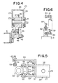
- a rack denoted by reference numeral 20 extends, as shown in Fig. 2, in the longitudinal direction of the base frame 6 of the warp carrying frame structure 5, i.e., in the direction X in which the warp carrying frame structure 5 moves, and the rack 20 is fixedly mounted to the base frame 6 through a bracket member 21 as clearly shown in Fig. 4.
- the rack 20 is engaged by a pinion 26 which is nonrotatably mounted on a pinion shaft 22 which in turn is freely rotatably supported through front and rear bearings 23 and 24 to a pinion support 25.
- the pinion 26 is freely rotatably supported by the pinion support 25.
- the pinion support 25 comprises a pair of front and rear plates 27 and 28 in which the front and rear bearings 23 and 24 are respectively mounted, an upper plate 29 extending between the front and rear plates 27 and 28 and covering the upper ends of the front and rear plates 27 and 28, and a pair of side plates 30 and 31 (Fig. 3).
- the pinion support 25 is freely rotatably supported through bearings 33 and 34 on one end of an intermediate shaft 32 which passes through the front and rear plates 27 and 28 of the pinion support 25.
- a bearing housing designated by reference numeral 35 is provided on a common bed 36 fixedly mounted on the stationary frame structure 3 of the warp drawing apparatus 2, and the intermediate shaft 32 is freely rotatably supported through bearings 37 and 38 of the bearing housing 35.
- the intermediate shaft 32 has an intermediate gear 39 mounted on one end thereof between the bearings 33 and 34, and has a driven bevel gear 40 mounted on the other end thereof.
- the intermediate gear 39 is engaged by the pinion 26, while the driven bevel gear 40 is engaged by a drive bevel gear 42 which is mounted on the output shaft 41a of a clutch brake 41 having a center axis perpendicular to the center axis of the intermediate shaft 32.
- the clutch brake 41 has at the opposite side of the output shaft 41a an input shaft 41b which is coupled to the output shaft 44a of a reduction gear 44 which is driven by means of a motor 43.
- the rotation of the motor 43 is reduced by the reduction gear 44 and transmitted to the clutch brake 41.
- the clutch mechanism (not shown) provided in the clutch brake 41 is in the operating position, the rotation of the motor 33 reduced by means of the reduction gear 44 is transmitted through the clutch brake 41, drive bevel gear 42, driven bevel gear 40 and through the intermediate gear 39 to the pinion 26, and the rack 20 is driven by rotation of the pinion 26, so that the warp carrying frame structure 5 is caused to move in the longitudinal direction X.
- the clutch mechanism of the clutch brake 41 is released and at the same time the rotation of the output shaft 41a of the clutch brake 41 is stopped by means of the brake (not shown) of the clutch brake 41, and therefore the movement of the warp carrying frame structure 5 is brought into a stop concurrently with the release of the clutch mechanism.
- the aforementioned motor 43, reduction gear 44, clutch brake 41, drive bevel gear 42, driven bevel gear 40, intermediate shaft 32, bearing housing 35 and intermediate gear 39 as a whole constitute pinion drive means 45 which is adapted to drive the pinion 26 and which is fixedly mounted on the common bed 36 on the stationary frame structure 3 of the warp drawing apparatus 2.
- a rack holding lever denoted by reference numeral 46 is freely rotatably supported through its pin 47 to the pinion support 25.
- the rack holding lever 46 has at its one end a rack holding roll 48 which is engageable with the rack 20 and which is freely rotatably supported on a pin 49 fixed to the lever 46.
- An actuator 50 comprising a cylinder 51 and a piston rod 52 fixed to the piston (not shown), is connected to the other end of the rack holding lever 46 and to the pinion support 25, and serves as drive means which drives the rack holding lever 46 and the pinion support 25 to rotate about the pin 47 and about the intermediate shaft 32, respectively, in such a manner that the rack holding roll 48 and the pinion 26 are moved toward and away from each other.
- the actuator 50 is connected to the side plate 31 of the pinion support 25 through a pair of bracket members 53 and 54 which are respectively rotatably supported at one ends thereof on pins 55 and 56 projecting from the actuator 50 and which are respectively fixed at the other ends thereof to the side plate 31 of the pinion support 25 by means of bolts 53a and 54a.
- On the piston rod 52 of the actuator 50 is threaded a cylindrical connection member 57 which is formed with a groove 57a in which the other end of the rack holding lever 46 is inserted.
- the actuator 50 is connected to the rack holding lever 46 through the connection member 57 and through a connection pin 58 which is passed through apertures formed in the connection member 57 and which is also passed through an aperture formed in the other end of the rack holding lever 46.
- the cylinder 51 of the actuator 50 is provided with a pair of inlet ports 51a and 51b through which working fluid, for example, air or oil under pressure is supplied to one or the other cylinder chamber (not shown) arranged across the piston of the cylinder.
- working fluid for example, air or oil under pressure
- the admission of the working fluid to one or the other cylinder chamber causes the piston rod 52 to project from and retract into the cylinder 51. Therefore, the pinion support 25 and the rack holding lever 46 are rotated by the movement of the piston rod 52 of the actuator 50.
- the pinion support 25 rotatable on the intermediate shaft 32 is connected to the pin 55 of the actuator 50 and since the rack holding lever 46 rotatable on the pin 47 is connected to the connection pin 58 of the piston rod 52, if the distance between the pins 55 and 58 is decreased, the pinion support 25 and the rack holding roll 48 are rotated away from each other, and on the other hand, if the distance between the pins 55 and 58 is increased, the pinion support 25 and the rack holding roll 48 are rotated toward each other. Namely, if the piston rod 52 projects from the cylinder 51, the rack holding roll 48 and the pinion 26 supported by the pinion support 25 are moved toward each other as shown by the solid lines in Fig. 3 and hold the rack 20 therebetween. If, on the other hand, the piston rod 52 retracts into the cylinder 51, the rack holding roll 48 and the pinion 26 are moved away from each other as shown by the broken lines in Fig. 3.
- a coil spring denoted by reference numeral 59 is interposed between the stationary frame structure 3 of the warp drawing apparatus 2 and the pinion support 25.
- the coil spring 59 is urged such that the pinion support 25 is rotated and the pinion 26 and the rack holding roll 48 are moved away from each other, and serves as an elastic member which regulates the rotation of the pinion support 25.
- the upper end of the coil spring 59 as clearly shown in Figs.
- connection bolt 61 is provided in the upper end of the post 62, and as shown by the broken lines in Fig.
- a proximity switch designated by reference numeral 65 is provided in the vicinity of the rear plate 28 of the pinion support 25 and fixed through a L-shaped bracket member 66 to the pinion support 25.
- a projection 67 is mounted on the stationary frame structure 3 of the warp drawing apparatus 2 in facing relationship with a lower end 65a of the proximity switch 65.
- the switch 65 serves to output a proximity signal, when the pinion support 25 is rotated downward and the space between the lower end 65a of the proximity switch 65 and the projection 67 becomes 1 to 3 mm for example. If the piston rod 52 of the actuator 50 projects, the rack holding lever 46 is first rotated upward and therefore the rack holding roll 48 is brought into engagement with the rack 20.
- the piston rod 52 further projects against the coil spring 59 to rotate the pinion support 25 toward the rack 20 so that the rack holding roll 48 and the pinion 26 is moved toward each other, and stops with the condition the pinion 26 is properly engaged with the rack 20.
- the lower end 65a of the proximity switch 65 fixed to the pinion support 25 is moved downward toward the projection 67 and the space therebetween becomes the aforesaid dimension (1 to 3 mm), so that the proximity switch 65 outputs the proximity signal, thereby being able to confirm whether the rack 20 is held by the pinion 26 and the rack holding roll 48.
- the amount of backlash between the pinion 26 and the rack 20 can be adjusted by adjusting in advance the distance that the piston rod 52 of the actuator 50 advances.
- the pinion 26 is driven to rotate about its own axis by the pinion drive means 45.
- the coil spring 59 is expanded as shown by the solid lines in Fig. 3 and the stop lever 60 of the pinion support 25 is moved away from the stop member 64.
- a photoelectric switch 68 is provided in the upper end portion of the warp drawing apparatus 2 and comprises a projector part for projecting a ray of light on the warp threads W held between the upper and lower beams 13 and 14 of the warp carrying frame structure 5, and a receiver part for receiving the reflected ray of the warp thread W and converting it into a control signal.
- the photoelectric switch 68 After the first one of the warp threads W, which are successively arranged in the longitudinal direction X along the front face 2a of the warp drawing apparatus 2, is drawn through the heddle eye by the warp drawing apparatus 2, the photoelectric switch 68 outputs the control signal to a control circuit (not shown) which controls the actuation of the pinion drive means 45.
- the control circuit outputs an actuation signal to the pinion drive means 45 in accordance with the control signal from the photoelectric switch 68, and actuates the clutch brake 41 of the pinion drive means 45 to drive the pinion drive means 45. Consequently, the pinion 26 is rotated about its own axis and the warp carrying frame structure 5 is moved through the rack 20 mounted on the structure 5. If the next warp thread W, which is arranged adjacent the warp thread W that has been drawn through the heddle eye, is advanced to the position of the projector part of the photoelectric switch 68, the photoelectric switch 68 receives the reflected ray of the warp thread W and again outputs the control signal to the control circuit.
- the control circuit outputs a stop signal to the pinion drive means 45, and the warp carrying frame structure 5 is stopped and held in a predetermined position of the stationary frame structure 3 of the warp drawing apparatus 2. Consequently, the warp thread W to be drawn through the heddle eye is properly positioned in the predetermined position.
- an additional photoelectric switch 68 is provided against the fault of the aforesaid photoelectric switch 68.
- the aforesaid proximity switch 65 is connected to the control circuit above described, and that an interlock circuit is provided in the control circuit in order that the pinion drive means 45 is driven after the rack 20 is held by the pinion 26 and rack holding roll 48.
- the warp drawing apparatus 2 As shown in Fig. 1, the warp carrying frame structure 5, in which a mass or pack of warp threads W wound around the warp beam 7 are held between the upper and lower beams 13 and 14 and arranged successively in the longitudinal direction of the longitudinal center axis of the warp beam 7, is arranged in facing relationship to the front face 2a of the warp drawing apparatus 2.
- the piston rod 52 of the actuator 50 is retracted into the cylinder 51 by supplying the working oil to one of the cylinder chambers, and the pinion 26 and the rack holding roll 48 are moved away from each other, and furthermore, with the stop lever 60 of the pinion support 25 fixed and held on the stop member 64 by the coil spring 59, the warp carrying frame structure 5 is arranged such that the rack 20 of the warp carrying frame structure 5 is positioned between the pinion 26 and the rack holding roll 48.
- the first one of the warp threads W which are held between the upper and lower warp beams 13 and 14 and arranged in the longitudinal direction, is positioned short of the photoelectric switch 68.
- the piston rod 52 of the actuator 50 is projected by supplying the working oil to the other chamber, and as shown by the solid lines in Fig. 3, the pinion 26 and the rack holding roll 48 move toward each other to hold the rack 20 therebetween, and the pinion 25 is brought into meshing engagement with the rack 20.
- the motor 43 of the pinion drive means 45 is driven, and since the first one of the warp threads W longitudinally arranged is arranged short of the position of the photoelectric switch 68, the control circuit outputs the actuation signal to the pinion drive means 45 in accordance with the control signal from the photoelectric switch 68.
- the clutch mechanism of the clutch brake 41 is coupled, and the rotation of the motor 44 is reduced through the reduction gear 44 and transmitted through the clutch brake 41, drive bevel gear 42, driven bevel gear 40 and through the intermediate gear 39 to the pinion 26.
- the rack 20 engaged by the pinion 26 is then driven and therefore the warp carrying frame structure 5 advances in the direction indicated by the arrow X in Fig. 2.
- the movement of the warp carrying frame structure 5 causes the warp thread W to approach the photoelectric switch 68.
- the switch 68 receives the reflected ray and outputs the control signal to the control circuit.
- the control circuit outputs the stop signal to the pinion drive means 45, and the connection of the clutch mechanism of the clutch brake 41 is released.
- the output shaft 41a of the clutch brake 41 is braked and the movement of the warp carrying frame structure 5 is rapidly brought into a stop.
- the warp carrying frame structure 5 is accurately stopped to the predetermined position and positioned.
- the warp thread W to be drawn through the heddle eye is accurately transferred in the predetermined.
- the pinion drive means 45 is driven according to the signal of the photoelectric switch 68, and the warp carrying frame structure 5 is moved and stopped, so that the next warp thread is transferred to the predetermined position.
- the aforesaid process is repeated in order that all of the warp threads held by the warp carrying frame structure 5 are drawn through the heddle eye by the warp drawing apparatus 2.
- the pinion support 25 can be rotated in accordance with the upward and downward movements of the rack 20, by the deformation of the coil spring 59 and with the condition that the rack 20 is held by the pinion 26 and rack holding roll 48 and that the pinion 26 is properly held in meshing engagement with the rack 20. Accordingly, the movement of the warp carrying frame structure 5 can be always maintained with high accuracy.
- the pinion drive means 45 is driven and stopped by the clutch mechanism of the clutch brake 41, and particularly since, when the pinion drive means 45 is brought into a stop, it is rapidly braked by the brake of the clutch brake 41, the movement of the warp carrying frame structure 5 also can be enhanced in accuracy.
- the rack 20 can be easily positioned between the pinion 26 and the rack holding roll 48, as previously indicated, and furthermore since the pinion 26 can be surely engaged with the rack 20 only by the actuation of the actuator 50, the replacement of the warp carrying frame structure 5, that is made five to ten times per day, can be very easily made.
- the pinion support 25 is rotated by means of the actuator 50, the rack 20 is held by the pinion 26 and the rack holding roll 48 with the pinion 26 and rack holding roll 48 engaged with each other with a suitable backlash, and furthermore by the deformation of the coil spring 59, the pinion support 25 is rotated in accordance with the upward and downward movements of the rack 20 so that the engagement of the pinion 26 with the rack 20 is maintained constant.
- the accuracy of movement of the warp carrying frame structure 5 can be assured independently of the irregularities of the floor 4.
- the warp threads are reliably passed through the heddle eye by the warp drawing apparatus 2, and the installation cost for the apparatus can be reduced.
- an improved warp transfer apparatus in which the accuracy of movement of the warp carrying frame structure is assured independently of the irregularities of the floor and in which the installation cost for the apparatus is reduced.
Landscapes
- Engineering & Computer Science (AREA)
- Textile Engineering (AREA)
- Auxiliary Weaving Apparatuses, Weavers' Tools, And Shuttles (AREA)
- Transmission Devices (AREA)
- Looms (AREA)
- Processing And Handling Of Plastics And Other Materials For Molding In General (AREA)
Applications Claiming Priority (2)
| Application Number | Priority Date | Filing Date | Title |
|---|---|---|---|
| JP1987160843U JPH0351347Y2 (de) | 1987-10-22 | 1987-10-22 | |
| JP160843/87 | 1987-10-22 |
Publications (2)
| Publication Number | Publication Date |
|---|---|
| EP0313182A2 true EP0313182A2 (de) | 1989-04-26 |
| EP0313182A3 EP0313182A3 (de) | 1991-02-27 |
Family
ID=15723608
Family Applications (1)
| Application Number | Title | Priority Date | Filing Date |
|---|---|---|---|
| EP19880305066 Withdrawn EP0313182A3 (de) | 1987-10-22 | 1988-06-03 | Vorrichtung zum Transferieren von Kettfäden |
Country Status (4)
| Country | Link |
|---|---|
| US (1) | US4878279A (de) |
| EP (1) | EP0313182A3 (de) |
| JP (1) | JPH0351347Y2 (de) |
| KR (1) | KR930000173B1 (de) |
Cited By (2)
| Publication number | Priority date | Publication date | Assignee | Title |
|---|---|---|---|---|
| WO1992007127A1 (de) * | 1990-10-23 | 1992-04-30 | Zellweger Uster Ag | Maschine zum automatischen einziehen von kettfäden |
| WO2011117678A1 (en) * | 2010-03-24 | 2011-09-29 | Cameron International Corporation | Compact-actuator gear set |
Families Citing this family (4)
| Publication number | Priority date | Publication date | Assignee | Title |
|---|---|---|---|---|
| US5243742A (en) * | 1991-10-25 | 1993-09-14 | Teijin Seiki Co., Ltd. | Warp supplying apparatus for a warp threading machine |
| DE4234563C2 (de) * | 1992-10-14 | 1996-02-29 | Dornier Gmbh Lindauer | Vorrichtung zur temporären Lagerung eines zum Weben vorbereiteten Kettwechselsystems |
| CH690783A5 (de) * | 1995-12-21 | 2001-01-15 | Staeubli Ag Zweigwerk Sargans | Verfahren und Vorrichtung zum Einziehen von Kettfäden. |
| DE102005019906B3 (de) * | 2005-04-29 | 2006-03-30 | Lindauer Dornier Gmbh | Webmaschine mit lösbarer Verbindung zwischen einem Antriebsmittel und dem Kettbaum einer Webmaschine |
Family Cites Families (8)
| Publication number | Priority date | Publication date | Assignee | Title |
|---|---|---|---|---|
| US1342896A (en) * | 1917-07-30 | 1920-06-08 | Barber Colman Co | Machine for operating upon warps |
| US1716549A (en) * | 1927-01-21 | 1929-06-11 | Firm Zellweger A G | Device for separating and supplying threads particularly to warpheddling machines |
| US2011115A (en) * | 1933-06-05 | 1935-08-13 | Barber Colman Co | Machine for operating upon warps |
| GB593660A (en) * | 1945-06-19 | 1947-10-22 | Ernest Matthias Feuerheerd | A needle-threading device |
| CH348937A (de) * | 1956-07-10 | 1960-09-15 | Zellweger Uster Ag | Vorrichtung zum Abteilen von kreuzeingelesenen Kettfäden |
| FR1227485A (fr) * | 1958-04-02 | 1960-08-22 | Zellweger Uster Ag | Bâti de montage des chaînes de tissage pour dispositifs de nouage des chaînes de tissage et analogues |
| US3741836A (en) * | 1968-11-06 | 1973-06-26 | W Williams | Method of splicing synthetic thermoplastic carpet yarn ends |
| JPS60224842A (ja) * | 1984-04-19 | 1985-11-09 | 帝人製機株式会社 | 糸通し方法およびその装置 |
-
1987
- 1987-10-22 JP JP1987160843U patent/JPH0351347Y2/ja not_active Expired
-
1988
- 1988-06-03 EP EP19880305066 patent/EP0313182A3/de not_active Withdrawn
- 1988-06-08 US US07/204,122 patent/US4878279A/en not_active Expired - Fee Related
- 1988-07-20 KR KR1019880009068A patent/KR930000173B1/ko not_active Expired - Fee Related
Cited By (6)
| Publication number | Priority date | Publication date | Assignee | Title |
|---|---|---|---|---|
| WO1992007127A1 (de) * | 1990-10-23 | 1992-04-30 | Zellweger Uster Ag | Maschine zum automatischen einziehen von kettfäden |
| TR25534A (tr) * | 1990-10-23 | 1993-05-01 | Zellweger Uster Ag | CÖZGü IPLIKLERININ OTOMATIK CEKIMLERINE YARAYAN MAKINA |
| WO2011117678A1 (en) * | 2010-03-24 | 2011-09-29 | Cameron International Corporation | Compact-actuator gear set |
| KR20130004578A (ko) * | 2010-03-24 | 2013-01-11 | 카메론 인터내셔널 코포레이션 | 소형 액츄에이터 기어 세트 |
| KR101697810B1 (ko) | 2010-03-24 | 2017-01-18 | 카메론 인터내셔널 코포레이션 | 소형 액츄에이터 기어 세트 |
| US9909683B2 (en) | 2010-03-24 | 2018-03-06 | Cameron International Corporation | Compact-actuator gear set |
Also Published As
| Publication number | Publication date |
|---|---|
| JPH0351347Y2 (de) | 1991-11-01 |
| KR930000173B1 (ko) | 1993-01-11 |
| KR890006889A (ko) | 1989-06-16 |
| JPH0165890U (de) | 1989-04-27 |
| US4878279A (en) | 1989-11-07 |
| EP0313182A3 (de) | 1991-02-27 |
Similar Documents
| Publication | Publication Date | Title |
|---|---|---|
| US4292864A (en) | Automatic magazine and feeder for automatic multi-mandrel lathe | |
| EP0313182A2 (de) | Vorrichtung zum Transferieren von Kettfäden | |
| US3760697A (en) | Apparatus for grooving and/or longitudinally cutting a continuous web | |
| US4203477A (en) | Material working machine mounting tools in several planes | |
| EP0516260A1 (de) | Vorrichtung zum Aufspannen von Druckplatten auf den Plattenzylinder | |
| US4372183A (en) | Program controlled punching and nibbling machine | |
| JP2941798B2 (ja) | 制御可能なよこ糸給糸把持装置及び織機特にグリッパ織機で製織するときのよこ糸屑を最小にするための装置 | |
| JPS591815B2 (ja) | 平たんな布帛制品の製造装置用の制動装置 | |
| US7644850B2 (en) | Stapling device | |
| DE3240211C2 (de) | Walzenzuführungseinrichtung | |
| CS268678B2 (en) | Automatic printing machine for text printing on motion picture film | |
| DE69518899T2 (de) | Motorgetriebene Pressvorrichtung | |
| US3595462A (en) | Device for regulating the operations of the friction welder | |
| GB2042383A (en) | Coil spring manufacturing machine | |
| EP0338153A1 (de) | Vorrichtung zur Herstellung von Federn | |
| US4744139A (en) | Apparatus for automatically adjusting the worktable of an electronic components insertion machine | |
| EP1155847B1 (de) | Druckmachine | |
| DE1123339B (de) | Vorrichtung zum Zusammenfuehren zweier in einer Klebevorrichtung miteinander zu verbindender und anschliessend einer Verarbeitungsmaschine, insbesondere einer Druckmaschine, zuzufuehrender Kartonbahnen | |
| US5970772A (en) | Positioning control device for guide apparatus | |
| US3890863A (en) | Stamping machine for slotting core plates | |
| EP1155822A2 (de) | Druckpresse | |
| GB2132928A (en) | An adjustable nip mechanism | |
| US5271434A (en) | Control mechanism for the rapier heads of weaving machines | |
| GB2112350A (en) | Robot | |
| KR810001911Y1 (ko) | 공작 기계 |
Legal Events
| Date | Code | Title | Description |
|---|---|---|---|
| PUAI | Public reference made under article 153(3) epc to a published international application that has entered the european phase |
Free format text: ORIGINAL CODE: 0009012 |
|
| AK | Designated contracting states |
Kind code of ref document: A2 Designated state(s): CH DE FR IT LI |
|
| PUAL | Search report despatched |
Free format text: ORIGINAL CODE: 0009013 |
|
| AK | Designated contracting states |
Kind code of ref document: A3 Designated state(s): CH DE FR IT LI |
|
| 17P | Request for examination filed |
Effective date: 19910403 |
|
| 17Q | First examination report despatched |
Effective date: 19920721 |
|
| STAA | Information on the status of an ep patent application or granted ep patent |
Free format text: STATUS: THE APPLICATION IS DEEMED TO BE WITHDRAWN |
|
| 18D | Application deemed to be withdrawn |
Effective date: 19921202 |