EP0313245A2 - Cartouche pour ruban encreur avec dispositif de réencrage - Google Patents
Cartouche pour ruban encreur avec dispositif de réencrage Download PDFInfo
- Publication number
- EP0313245A2 EP0313245A2 EP88309443A EP88309443A EP0313245A2 EP 0313245 A2 EP0313245 A2 EP 0313245A2 EP 88309443 A EP88309443 A EP 88309443A EP 88309443 A EP88309443 A EP 88309443A EP 0313245 A2 EP0313245 A2 EP 0313245A2
- Authority
- EP
- European Patent Office
- Prior art keywords
- ink
- roller
- metering means
- inking
- ribbon
- Prior art date
- Legal status (The legal status is an assumption and is not a legal conclusion. Google has not performed a legal analysis and makes no representation as to the accuracy of the status listed.)
- Granted
Links
Images

Classifications
-
- B—PERFORMING OPERATIONS; TRANSPORTING
- B41—PRINTING; LINING MACHINES; TYPEWRITERS; STAMPS
- B41J—TYPEWRITERS; SELECTIVE PRINTING MECHANISMS, i.e. MECHANISMS PRINTING OTHERWISE THAN FROM A FORME; CORRECTION OF TYPOGRAPHICAL ERRORS
- B41J31/00—Ink ribbons; Renovating or testing ink ribbons
- B41J31/14—Renovating or testing ink ribbons
- B41J31/16—Renovating or testing ink ribbons while fitted in the machine using the ink ribbons
-
- B—PERFORMING OPERATIONS; TRANSPORTING
- B41—PRINTING; LINING MACHINES; TYPEWRITERS; STAMPS
- B41J—TYPEWRITERS; SELECTIVE PRINTING MECHANISMS, i.e. MECHANISMS PRINTING OTHERWISE THAN FROM A FORME; CORRECTION OF TYPOGRAPHICAL ERRORS
- B41J32/00—Ink-ribbon cartridges
- B41J32/02—Ink-ribbon cartridges for endless ribbons
Definitions
- the present invention relates to a cartridge for an inked ribbon with a re-inking device, of the type set forth in the introductory part of claim 1.
- the ink metering means comprises a blade which is in contact with a roller in contact with the ribbon and which provides for the ribbon feed.
- the ink metering means is partially housed in an inking reservoir which in turn is accommodated in a recess in the container; a spring urges the entire inking reservoir, with its metering means towards the feed roller.
- That re-inking device suffers from the disadvantage that the inking reservoir can allow the ink to be easily drawn out.
- the form of the feed roller which is subdivided into rings and the essential purpose of which is to engage the ribbon for the feed thereof is not suitable for providing for regular distribution of the ink over the ribbon to be re-inked.
- the object of the present invention is therefore to provide a re-inking device for an inked ribbon in a cartridge, of low cost, which is simple, reliable and which at the same time permits uniform re-inking of the ribbon.
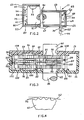
- the re-inking device which is generally indicated at 11 is applied by way of example to a cartridge 12 which, not being principal subject-matter of the present invention, is described only in respect of part thereof in order better to set forth the use of the re-inking device 11.
- the cartridge 12 comprises a container 13 having abottom 14 and a series of internal walls 16, 17 and 18 such as to define a space 19.
- the container 13 is closed upwardly by a cover 21 and is delimited by a rear wall 22, a front wall 23, a right-hand side wall 24 and a left-hand side wall 26.
- the cartridge 12 comprises, projecting from the rear wall 22, two arms 27 and 28 which are suitably shaped and which at their ends have two apertures 29 and 31 respectively for permitting a portion of an inked ribbon 32 to pass therethrough and be guided to the outside.
- the arms 27 and 28 are connected by a reinforcing rib 33.
- the inked ribbon 32 is of the closed loop type and is disposed in randomly distributed turns in a magazine 34 in the container 13.
- the ribbon 32 issues from the container 13 by way of the aperture 31, returns into the container 13 through the aperture 29 and is guided to the interior of the container by a fixed guide 39 and a guide bush 41 to be directed in tangential relationship and in contact with an inking roller 42.
- the ribbon 32 is then engaged by a pair of rollers which are generally indicated at 43 for the undirectional feed movement and is re-introduced into the magazine 34.
- the re-inking device 11 comprises a supply reservoir for the ink as indicated at 51 (see Figure 2), comprising a soft porous body of low density formed for example by a polyester felt pad and capable of containing the ink 50 by impregnation, and an ink metering means 52 comprising a porous but compact body of high density and of reasonable rigidity, formed for example by a felt of wool which is treated with epoxy resin.
- the ink metering means 52 has a first portion in close contact with the supply reservoir 51 and a second portion in contact with the inking roller 42 for permitting capillary flow of the ink 50 from the reservoir 51 to the inking roller 42.
- the reservoir for the ink or polyester felt pad 51 is protected from losing ink 50 by a casing formed by a closed cassette or box 53 which in turn is housed within the container 13 (see Figure 1).
- the box 53 comprises two recesses 54 and 56 for accommodating two positioning pins 57 and 58 which project from the bottom 14, within the container 13, for removably fixing the box 53 to the container 13, positioning it adjacent to a portion of the ribbon 32, the guide bush 41 and the inking roller 42, as is clearly visible in Figure 1.
- the box 53 comprises two internal blades 59 (see Figure 2) and 61 and two pins 62 and 63 arranged for positioning on the one hand the polyester felt 51 and for holding a part of the metering means 52 closely in contact against the polyester felt 51 by virtue of the compliance of the material.
- the box 53 having the recesses 54 and 56 is formed by a bottom 64 and a series of walls 66, 67, 68, 69, 71 (see Figure 1), and 72 each having a rebate 65 at its upper edge.
- the box 53 is closed in known fashion, for example a cover 73 is ultrasonically welded to the rebates 65 of the walls 66, 67, 68, 69, 71 and 72 after the reservoir 51 and the metering means 52 have been positioned within the box 53.
- the box 53 comprises a lateral opening 74 (see Figure 2) to permit the metering means 52 to be passed therethrough and positioned therein.
- the opening 74 is of a predetermined shape of frustoconical section such as to reduce and slightly compress the part of the metering means 52 which is accommodated in the opening 74, in such a way as to prevent leakage of the ink 50 contained in the reservoir 51, except for that which passes by capillary flow along the fibres of the metering means 52.
- the ink 50 is introduced into the box 53 after the box is sealingly closed, in per se known manner, for example using a syringe system for injecting a predetermined amount which is preset such as to be completely absorbed by the reservoir 51 and the metering means 52, by way of a small hole 75 provided in the wall 66.
- the internal blades 59 and 61 are spaced from the wall 66 in such a way as to form a space 80 which is kept at ambient pressure by virtue of the presence of the hole 75 and capable of ensuring a normal discharge flow of ink 50 by way of the metering means 52.
- the pins 62 and 63 are spaced from the wall 68 to form a space 85 adjacent to the aperture 74.
- the pins 62 and 63 of the box and the opening 74 define a reference axis 70 for the metering means 52, which is substantially parallel to the wall 68.
- the positioning pins 57 (see Figure 1) and 58 of the container 13 predetermine a position of the box 53 within the container such that the axis 70 of the metering means 52 is disposed along a plane intermediate reference plane tangential to the periphery and a plane passing through the axis of the inking roller 42, both parallel to the wall 68.
- the projecting portion of the metering means 52 is obliged to flex and bears against the outside surface of the teeth 76 of the roller 42. In addition it tends to return to its original position due to the resiliency of the materials of which it is composed and therefore applies a pressure in the region of contact with the outside surface of the teeth 76, which is sufficient to ensure that the ink passes on to the teeth 76.
- the inking roller 42 is rotatable on a pin 77 which projects from the bottom 14, and has the tips of the teeth 76 of rounded section (see Figure 4) so as not to cause wear on the ribbon 32 and the portion of the metering means 52 (see Figure 1) which are held in contact with the teeth 76. Capillary flow of the ink 50 from the metering means 52 to the outside surface of the teeth 76 and subsequently to the ribbon 32 therefore takes place in a smooth and reliable fashion.
- the pair of rollers 43 comprise a toothed drive roller 78 which is always engaged with the inking roller 42 and a toothed drive roller 79.
- the drive and driven rollers 78 and 79 are each formed in one piece comprising three toothed wheels or gears which are spaced from each other by two sleeve portions 81 (see Figure 3) and 82.
- the drive roller 78 is rotatable between an opening 83 in the bottom 14 and an opening 84 in the cover 21 and can be connected in per se known manner for example to a drive shaft 86 which is substantially similar to the drive shaft 66 shown in Figure 3 of Italian patent No 1 024 899 when the cartridge 12 is mounted on a typewriter.
- the drive roller 78 is supported by a support 87 having two flanges 88 with semicylindrical seats 90 engaged with the two sleeve portions 81 and a pin 89 which is housed in a cylindrical seat 91 in the bottom 14.
- the drive roller 78 has a gripping portion 92 which projects from the cover 21 and which is capable of being manually rotated for manual feed of the inked roller 32.
- the driven roller 79 is rotatable by means of the end portions 93 and 94 which are accommodated in respective slots 96 and 97 in the bottom 14 and the cover 21.
- the driver roller 79 is supported by a pressing support 98 having two flanges 99 with semicylindrical seats 100 engaged with the two sleeves 82 and a cylindrical pin 101 housed in a radial groove 102 in the bottom 14.
- a leaf spring 103 has one end 104 (see Figure 1) received in a recess 105 in the container 13, with the other end 106 engaged with the pressing means 98 and an intermediate portion co-operating with a preloading member 107 of the container 13 for holding the driven toothed roller 79 constantly in mesh and engaged with the drive toothed roller 78.
- the structure of the rollers 78 and 79 and the associated supports 87 and 98 as described hereinbefore is optimised to produce feed movement of the ribbon without obstruction and jamming in per se known manner.
- the cover 21 (see Figure 3) comprises ribs 108 capable of co-operating with the upper portions of the support 87, the pressing means 98 and the rollers 78 and 79 to prevent undesired movements of the various components when the cartridge 12 is not mounted on the typewriter.
- the guide bush 41 (see Figure 1) is rotatable on a pin 109 on the bottom 14 and the ribbon 32 is engaged around the guide bush 41 to be directed towards the teeth 76 of the inking roller 42 and subsequently towards the pair of rollers 43, following an inclined path of movement as shown in Figure 4.
- the ink metering means 52 (see Figures 1 and 2) is of substantially parallelepipedic form and is of a height equal to the height of the inking roller 42, the guide bush 41 and the inked ribbon 32.
- the drive shaft 86 rotates with the drive roller 78 and the driven roller 79 and the inked ribbon 32 is moved with a unidirectional feed movement.
- the projecting portion of the metering means 52 is always in contact with the teeth 76 of the inking roller 42 and the ink 50 thus flows from the ink reservoir 51 to the rounded external surface of the teeth 76. Since the inking roller 42 is always engaged with the drive roller 78, rotary movement thereof causes rotary movement of the inking roller 42.
- the teeth 76 engage the ribbon 32 and the ink 50 deposited on the teeth 76 passes to the ribbon 32. That therefore provides for uniform and controlled re-inking of the ribbon 32.
- the reservoir 51 and a part of the metering means 52 are housed in a closed box 53 having a single opening 74 for the metering means 52 to pass therethrough; the ink 50 cannot therefore escape from any part of the arrangement, except by way of the metering means 52.
- the box 53 does not lose ink 50, it permits assembly of the reservoir 51 and the metering means 52, and loading of the ink 50 and subsequent storage of the box, as a unit which is separate and separable from the cartridge.
- the cartridge 12 is designed for that purpose, it is possible to replace an exhausted box by a fresh box.
- cartridge 12 for an inked ribbon 32 with the re-inking device 11 may be the subject of modifications and improvements both in regard to the shape and the arrangement of the various components and parts without departing from the scope of the invention.
Landscapes
- Impression-Transfer Materials And Handling Thereof (AREA)
- Beverage Vending Machines With Cups, And Gas Or Electricity Vending Machines (AREA)
Priority Applications (1)
| Application Number | Priority Date | Filing Date | Title |
|---|---|---|---|
| AT88309443T ATE84259T1 (de) | 1987-10-20 | 1988-10-10 | Farbbandkassette mit nachtraenk-vorrichtung. |
Applications Claiming Priority (2)
| Application Number | Priority Date | Filing Date | Title |
|---|---|---|---|
| IT6787287 | 1987-10-20 | ||
| IT8767872A IT1211410B (it) | 1987-10-20 | 1987-10-20 | Cartuccia per un nastro inchiostrato con dispositivo di reinchiostra zione |
Publications (3)
| Publication Number | Publication Date |
|---|---|
| EP0313245A2 true EP0313245A2 (fr) | 1989-04-26 |
| EP0313245A3 EP0313245A3 (en) | 1989-08-30 |
| EP0313245B1 EP0313245B1 (fr) | 1993-01-07 |
Family
ID=11305973
Family Applications (1)
| Application Number | Title | Priority Date | Filing Date |
|---|---|---|---|
| EP88309443A Expired - Lifetime EP0313245B1 (fr) | 1987-10-20 | 1988-10-10 | Cartouche pour ruban encreur avec dispositif de réencrage |
Country Status (7)
| Country | Link |
|---|---|
| EP (1) | EP0313245B1 (fr) |
| AT (1) | ATE84259T1 (fr) |
| CA (1) | CA1334564C (fr) |
| DE (1) | DE3877319T2 (fr) |
| ES (1) | ES2038306T3 (fr) |
| IT (1) | IT1211410B (fr) |
| ZA (1) | ZA887793B (fr) |
Cited By (3)
| Publication number | Priority date | Publication date | Assignee | Title |
|---|---|---|---|---|
| EP0417488A1 (fr) * | 1989-09-15 | 1991-03-20 | Lexmark International, Inc. | Cartouche à ruban comprenant un mécanisme de réencrage pour rubans encreurs sans fin |
| EP0428123A1 (fr) * | 1989-11-16 | 1991-05-22 | Incas Holding S.P.A. | Cassette contenant un ruban encreur |
| WO1995032870A1 (fr) * | 1994-05-26 | 1995-12-07 | Baltea S.P.A. | Dispositif d'alimentation de ruban d'impression |
Family Cites Families (5)
| Publication number | Priority date | Publication date | Assignee | Title |
|---|---|---|---|---|
| US4091914A (en) * | 1977-02-22 | 1978-05-30 | Porelon, Inc. | Wear-activated ribbon reinker |
| JPS6044384A (ja) * | 1983-08-22 | 1985-03-09 | エヌ・シー・アール・コーポレーション | インキ供給機構付リボン・カ−トリツジ |
| DE3535876A1 (de) * | 1985-10-08 | 1987-04-09 | Turbon International | Farbbandkassette fuer gestopfte endlosfarbbaender |
| IT1187942B (it) * | 1986-02-28 | 1987-12-23 | Olivetti & Co Spa | Cartucce per nastro inchiostrato con dispositivo di reinchiostrazione |
| US4653947A (en) * | 1986-03-05 | 1987-03-31 | Echodata Corporation | Reinking device for ribbon cartridge |
-
1987
- 1987-10-20 IT IT8767872A patent/IT1211410B/it active
-
1988
- 1988-10-07 CA CA000579581A patent/CA1334564C/fr not_active Expired - Fee Related
- 1988-10-10 DE DE8888309443T patent/DE3877319T2/de not_active Expired - Lifetime
- 1988-10-10 EP EP88309443A patent/EP0313245B1/fr not_active Expired - Lifetime
- 1988-10-10 AT AT88309443T patent/ATE84259T1/de not_active IP Right Cessation
- 1988-10-10 ES ES198888309443T patent/ES2038306T3/es not_active Expired - Lifetime
- 1988-10-19 ZA ZA887793A patent/ZA887793B/xx unknown
Cited By (5)
| Publication number | Priority date | Publication date | Assignee | Title |
|---|---|---|---|---|
| EP0417488A1 (fr) * | 1989-09-15 | 1991-03-20 | Lexmark International, Inc. | Cartouche à ruban comprenant un mécanisme de réencrage pour rubans encreurs sans fin |
| EP0428123A1 (fr) * | 1989-11-16 | 1991-05-22 | Incas Holding S.P.A. | Cassette contenant un ruban encreur |
| US5145268A (en) * | 1989-11-16 | 1992-09-08 | Incas Holding S.P.A. | Cassette containing an inked ribbon |
| WO1995032870A1 (fr) * | 1994-05-26 | 1995-12-07 | Baltea S.P.A. | Dispositif d'alimentation de ruban d'impression |
| US5820278A (en) * | 1994-05-26 | 1998-10-13 | Olivetti Lexikon S.P.A. | Printing ribbon feeding device |
Also Published As
| Publication number | Publication date |
|---|---|
| EP0313245A3 (en) | 1989-08-30 |
| CA1334564C (fr) | 1995-02-28 |
| ATE84259T1 (de) | 1993-01-15 |
| EP0313245B1 (fr) | 1993-01-07 |
| IT8767872A0 (it) | 1987-10-20 |
| ES2038306T3 (es) | 1993-07-16 |
| ZA887793B (en) | 1989-07-26 |
| DE3877319T2 (de) | 1993-07-22 |
| IT1211410B (it) | 1989-10-18 |
| DE3877319D1 (de) | 1993-02-18 |
Similar Documents
| Publication | Publication Date | Title |
|---|---|---|
| US4213715A (en) | Ink ribbon cartridge having a replaceable ribbon magazine | |
| US4616942A (en) | Ribbon cassette with re-inking mechanism | |
| US4747711A (en) | Cartridge for an inked ribbon with a re-inking device | |
| US4653947A (en) | Reinking device for ribbon cartridge | |
| US3831731A (en) | Self-tensioning and re-inking ribbon cartridge for endless ribbons | |
| KR920000440B1 (ko) | 재잉킹 롤러와 이송 롤러 조립체 | |
| US4109790A (en) | Supporting cover for an ink roll means | |
| EP0313245A2 (fr) | Cartouche pour ruban encreur avec dispositif de réencrage | |
| US4273453A (en) | Selectively engageable ribbon re-inking device for ink ribbon cartridge | |
| US4536098A (en) | Self-regulating ribbon re-inking device | |
| US4741639A (en) | Cartridge for an inked ribbon with a re-inking pad | |
| EP0417488B1 (fr) | Cartouche à ruban comprenant un mécanisme de réencrage pour rubans encreurs sans fin | |
| EP0210755B1 (fr) | Dispositif d'encrage d'un ruban dans une cassette | |
| JPH0224186A (ja) | タイプライターの修正リボン用カートリッジ | |
| EP0314254B1 (fr) | Cartouche pour encre et son rouleau de transfert | |
| JPH0460030B2 (fr) | ||
| US5401108A (en) | Ink retaining mass for reinking ribbons in ink cartridges | |
| CA1203431A (fr) | Dispositif de reencrage de ruban auto-regulateur | |
| JPH0536705Y2 (fr) | ||
| US5567064A (en) | Ribbon cartridge | |
| EP0260834A2 (fr) | Cassette pour ruban d'impression | |
| JPH0423019Y2 (fr) | ||
| JPS5913081Y2 (ja) | プリンタ用インクリボンカセツト |
Legal Events
| Date | Code | Title | Description |
|---|---|---|---|
| PUAI | Public reference made under article 153(3) epc to a published international application that has entered the european phase |
Free format text: ORIGINAL CODE: 0009012 |
|
| AK | Designated contracting states |
Kind code of ref document: A2 Designated state(s): AT BE CH DE ES FR GB LI NL |
|
| PUAL | Search report despatched |
Free format text: ORIGINAL CODE: 0009013 |
|
| AK | Designated contracting states |
Kind code of ref document: A3 Designated state(s): AT BE CH DE ES FR GB LI NL |
|
| 17P | Request for examination filed |
Effective date: 19900227 |
|
| 17Q | First examination report despatched |
Effective date: 19910607 |
|
| GRAA | (expected) grant |
Free format text: ORIGINAL CODE: 0009210 |
|
| AK | Designated contracting states |
Kind code of ref document: B1 Designated state(s): AT BE CH DE ES FR GB LI NL |
|
| REF | Corresponds to: |
Ref document number: 84259 Country of ref document: AT Date of ref document: 19930115 Kind code of ref document: T |
|
| REF | Corresponds to: |
Ref document number: 3877319 Country of ref document: DE Date of ref document: 19930218 |
|
| ET | Fr: translation filed | ||
| REG | Reference to a national code |
Ref country code: ES Ref legal event code: FG2A Ref document number: 2038306 Country of ref document: ES Kind code of ref document: T3 |
|
| PLBE | No opposition filed within time limit |
Free format text: ORIGINAL CODE: 0009261 |
|
| STAA | Information on the status of an ep patent application or granted ep patent |
Free format text: STATUS: NO OPPOSITION FILED WITHIN TIME LIMIT |
|
| 26N | No opposition filed | ||
| REG | Reference to a national code |
Ref country code: GB Ref legal event code: IF02 |
|
| PGFP | Annual fee paid to national office [announced via postgrant information from national office to epo] |
Ref country code: AT Payment date: 20021011 Year of fee payment: 15 |
|
| PGFP | Annual fee paid to national office [announced via postgrant information from national office to epo] |
Ref country code: NL Payment date: 20021031 Year of fee payment: 15 |
|
| PGFP | Annual fee paid to national office [announced via postgrant information from national office to epo] |
Ref country code: BE Payment date: 20021219 Year of fee payment: 15 |
|
| PG25 | Lapsed in a contracting state [announced via postgrant information from national office to epo] |
Ref country code: AT Free format text: LAPSE BECAUSE OF NON-PAYMENT OF DUE FEES Effective date: 20031010 |
|
| PG25 | Lapsed in a contracting state [announced via postgrant information from national office to epo] |
Ref country code: BE Free format text: LAPSE BECAUSE OF NON-PAYMENT OF DUE FEES Effective date: 20031031 |
|
| BERE | Be: lapsed |
Owner name: C. *OLIVETTI & C. S.P.A. Effective date: 20031031 |
|
| PG25 | Lapsed in a contracting state [announced via postgrant information from national office to epo] |
Ref country code: NL Free format text: LAPSE BECAUSE OF NON-PAYMENT OF DUE FEES Effective date: 20040501 |
|
| NLV4 | Nl: lapsed or anulled due to non-payment of the annual fee |
Effective date: 20040501 |
|
| PGFP | Annual fee paid to national office [announced via postgrant information from national office to epo] |
Ref country code: ES Payment date: 20071120 Year of fee payment: 20 Ref country code: DE Payment date: 20071004 Year of fee payment: 20 |
|
| PGFP | Annual fee paid to national office [announced via postgrant information from national office to epo] |
Ref country code: CH Payment date: 20071015 Year of fee payment: 20 |
|
| PGFP | Annual fee paid to national office [announced via postgrant information from national office to epo] |
Ref country code: FR Payment date: 20071009 Year of fee payment: 20 Ref country code: GB Payment date: 20071010 Year of fee payment: 20 |
|
| REG | Reference to a national code |
Ref country code: CH Ref legal event code: PL |
|
| REG | Reference to a national code |
Ref country code: GB Ref legal event code: PE20 Expiry date: 20081009 |
|
| REG | Reference to a national code |
Ref country code: ES Ref legal event code: FD2A Effective date: 20081011 |
|
| PG25 | Lapsed in a contracting state [announced via postgrant information from national office to epo] |
Ref country code: ES Free format text: LAPSE BECAUSE OF EXPIRATION OF PROTECTION Effective date: 20081011 |
|
| PG25 | Lapsed in a contracting state [announced via postgrant information from national office to epo] |
Ref country code: GB Free format text: LAPSE BECAUSE OF EXPIRATION OF PROTECTION Effective date: 20081009 |