EP0314536A2 - Appareil électrostatique de formation d'images - Google Patents
Appareil électrostatique de formation d'images Download PDFInfo
- Publication number
- EP0314536A2 EP0314536A2 EP88402491A EP88402491A EP0314536A2 EP 0314536 A2 EP0314536 A2 EP 0314536A2 EP 88402491 A EP88402491 A EP 88402491A EP 88402491 A EP88402491 A EP 88402491A EP 0314536 A2 EP0314536 A2 EP 0314536A2
- Authority
- EP
- European Patent Office
- Prior art keywords
- gear
- motor
- roller
- transmission system
- pickup roller
- Prior art date
- Legal status (The legal status is an assumption and is not a legal conclusion. Google has not performed a legal analysis and makes no representation as to the accuracy of the status listed.)
- Granted
Links
Images


Classifications
-
- G—PHYSICS
- G03—PHOTOGRAPHY; CINEMATOGRAPHY; ANALOGOUS TECHNIQUES USING WAVES OTHER THAN OPTICAL WAVES; ELECTROGRAPHY; HOLOGRAPHY
- G03G—ELECTROGRAPHY; ELECTROPHOTOGRAPHY; MAGNETOGRAPHY
- G03G15/00—Apparatus for electrographic processes using a charge pattern
- G03G15/65—Apparatus which relate to the handling of copy material
-
- G—PHYSICS
- G03—PHOTOGRAPHY; CINEMATOGRAPHY; ANALOGOUS TECHNIQUES USING WAVES OTHER THAN OPTICAL WAVES; ELECTROGRAPHY; HOLOGRAPHY
- G03G—ELECTROGRAPHY; ELECTROPHOTOGRAPHY; MAGNETOGRAPHY
- G03G15/00—Apparatus for electrographic processes using a charge pattern
- G03G15/06—Apparatus for electrographic processes using a charge pattern for developing
- G03G15/08—Apparatus for electrographic processes using a charge pattern for developing using a solid developer, e.g. powder developer
- G03G15/09—Apparatus for electrographic processes using a charge pattern for developing using a solid developer, e.g. powder developer using magnetic brush
- G03G15/0921—Details concerning the magnetic brush roller structure, e.g. magnet configuration
- G03G15/0935—Details concerning the magnetic brush roller structure, e.g. magnet configuration relating to bearings or driving mechanism
-
- G—PHYSICS
- G03—PHOTOGRAPHY; CINEMATOGRAPHY; ANALOGOUS TECHNIQUES USING WAVES OTHER THAN OPTICAL WAVES; ELECTROGRAPHY; HOLOGRAPHY
- G03G—ELECTROGRAPHY; ELECTROPHOTOGRAPHY; MAGNETOGRAPHY
- G03G15/00—Apparatus for electrographic processes using a charge pattern
- G03G15/20—Apparatus for electrographic processes using a charge pattern for fixing, e.g. by using heat
- G03G15/2003—Apparatus for electrographic processes using a charge pattern for fixing, e.g. by using heat using heat
- G03G15/2014—Apparatus for electrographic processes using a charge pattern for fixing, e.g. by using heat using heat using contact heat
- G03G15/2064—Apparatus for electrographic processes using a charge pattern for fixing, e.g. by using heat using heat using contact heat combined with pressure
-
- G—PHYSICS
- G03—PHOTOGRAPHY; CINEMATOGRAPHY; ANALOGOUS TECHNIQUES USING WAVES OTHER THAN OPTICAL WAVES; ELECTROGRAPHY; HOLOGRAPHY
- G03G—ELECTROGRAPHY; ELECTROPHOTOGRAPHY; MAGNETOGRAPHY
- G03G15/00—Apparatus for electrographic processes using a charge pattern
- G03G15/75—Details relating to xerographic drum, band or plate, e.g. replacing, testing
- G03G15/757—Drive mechanisms for photosensitive medium, e.g. gears
-
- G—PHYSICS
- G03—PHOTOGRAPHY; CINEMATOGRAPHY; ANALOGOUS TECHNIQUES USING WAVES OTHER THAN OPTICAL WAVES; ELECTROGRAPHY; HOLOGRAPHY
- G03G—ELECTROGRAPHY; ELECTROPHOTOGRAPHY; MAGNETOGRAPHY
- G03G2215/00—Apparatus for electrophotographic processes
- G03G2215/00362—Apparatus for electrophotographic processes relating to the copy medium handling
- G03G2215/00367—The feeding path segment where particular handling of the copy medium occurs, segments being adjacent and non-overlapping. Each segment is identified by the most downstream point in the segment, so that for instance the segment labelled "Fixing device" is referring to the path between the "Transfer device" and the "Fixing device"
- G03G2215/00396—Pick-up device
-
- G—PHYSICS
- G03—PHOTOGRAPHY; CINEMATOGRAPHY; ANALOGOUS TECHNIQUES USING WAVES OTHER THAN OPTICAL WAVES; ELECTROGRAPHY; HOLOGRAPHY
- G03G—ELECTROGRAPHY; ELECTROPHOTOGRAPHY; MAGNETOGRAPHY
- G03G2215/00—Apparatus for electrophotographic processes
- G03G2215/00362—Apparatus for electrophotographic processes relating to the copy medium handling
- G03G2215/00367—The feeding path segment where particular handling of the copy medium occurs, segments being adjacent and non-overlapping. Each segment is identified by the most downstream point in the segment, so that for instance the segment labelled "Fixing device" is referring to the path between the "Transfer device" and the "Fixing device"
- G03G2215/00405—Registration device
-
- G—PHYSICS
- G03—PHOTOGRAPHY; CINEMATOGRAPHY; ANALOGOUS TECHNIQUES USING WAVES OTHER THAN OPTICAL WAVES; ELECTROGRAPHY; HOLOGRAPHY
- G03G—ELECTROGRAPHY; ELECTROPHOTOGRAPHY; MAGNETOGRAPHY
- G03G2215/00—Apparatus for electrophotographic processes
- G03G2215/00362—Apparatus for electrophotographic processes relating to the copy medium handling
- G03G2215/00367—The feeding path segment where particular handling of the copy medium occurs, segments being adjacent and non-overlapping. Each segment is identified by the most downstream point in the segment, so that for instance the segment labelled "Fixing device" is referring to the path between the "Transfer device" and the "Fixing device"
- G03G2215/00417—Post-fixing device
- G03G2215/00421—Discharging tray, e.g. devices stabilising the quality of the copy medium, postfixing-treatment, inverting, sorting
-
- G—PHYSICS
- G03—PHOTOGRAPHY; CINEMATOGRAPHY; ANALOGOUS TECHNIQUES USING WAVES OTHER THAN OPTICAL WAVES; ELECTROGRAPHY; HOLOGRAPHY
- G03G—ELECTROGRAPHY; ELECTROPHOTOGRAPHY; MAGNETOGRAPHY
- G03G2215/00—Apparatus for electrophotographic processes
- G03G2215/00362—Apparatus for electrophotographic processes relating to the copy medium handling
- G03G2215/00535—Stable handling of copy medium
- G03G2215/00679—Conveying means details, e.g. roller
Definitions
- the present invention relates to a novel structure of an image forming apparatus such as an electrostatic printer or a copying apparatus.
- an electrostatic printer comprises a photoconductive drum around which a series of elements are arranged for forming a latent image on the surface of the drum, developing a toner image from the latent image, and transferring the toner image to a medium.
- These elements include a precharger, a latent image former, a developer, a transfer charger, a discharger and a cleaner.
- a hopper is provided for accommodating a medium to be printed in a cut sheet form.
- a series of rollers are provided for conveying the medium through the printer, including a pickup roller for removing the cut sheets one by one from the hopper, a regist roller for introducing the cut sheets into the image-transferring zone, a guide roller for guiding the cut sheets in synchronism with the rotation of the photoconductive drum during the image transferring operation, a heat roller for fixing the toner image on the cut sheets, and an eject roller for discharging the cut sheets from the printer.
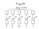
- the conventional electrostatic printer having such a structure has the driving system shown diagrammatically shown in Fig. 24.
- each of the rotating elements i.e., the photoconductive drum and roller
- a magnetic clutch for selectively connecting each element with a drive source (an electric motor), and thus the respective rotating elements can be independently controlled.
- Magnetic clutches are expensive, and the provision of same increases the cost of manufacturing the printer, and further, the size of the printer is necessarily increased.
- an object of the present invention is to provide a compact size printer at a reduced manufacturing cost.
- Another object of the present invention is to provide a printer having a structure such that a jam can be easily cleared.
- an image forming apparatus such as an electrostatic printer which comprises a rotating image carrier, such as a photoconductive drum a developer for forming a toner image on a surface of the image carrier, a pickup roller for removing a medium in a cut sheet form from a hopper, a regist roller for introducing the cut sheets removed by the pickup roller into a printing zone, a fuser for fixing the toner image on the cut sheets, and an eject roller for discharging the cut sheets from the printing zone.
- a rotating image carrier such as a photoconductive drum a developer for forming a toner image on a surface of the image carrier
- a pickup roller for removing a medium in a cut sheet form from a hopper
- a regist roller for introducing the cut sheets removed by the pickup roller into a printing zone
- a fuser for fixing the toner image on the cut sheets
- an eject roller for discharging the cut sheets from the printing zone.
- the printer according to the present invention is characterized in that a single motor selectively rotatable in the normal direction and the reverse direction in accordance with commands output from a control unit is provided for driving the rotating elements; a torque derived from the motor being transmitted, on one hand, to the pickup roller through a first transmission system incorporating a one-way clutch, which transmits only one directional rotation of the motor, and on the other hand to torque is transmitted to the rotating elements other than pickup roller through a second transmission system incorporating another one-way clutch which transmits only the opposite directional rotation of the motor.
- the motor rotates in one direction (normal rotation) and the pickup roller is driven through the first transmission system to remove the cut sheets from the hopper. Thereafter, the motor rotates in the reverse direction and the other rotating elements are driven through the second transmission system to convey the cut sheets through the printing zone while forming and fixing a toner image on the cut sheets. Therefore, when a cut sheet is in the image-transfer zone, the removal of the next cut sheet from a hopper is absolutely inhibited.
- the structure of the transmission system can be simplified, resulting in a compact and low cost printer.
- an electrostatic printer in which housing accommodating the elements of the printer is a clam type, comprising a lower cover unit and an upper frame unit hinged to the former at the rear end thereof so that the units are detachably connected to each other, and in which the motor, the rotating image carrier, the developer, and a gear box constituting a part of the transmission system is provided in the lower cover unit and the rollers for transporting the cut sheets are provided in the upper frame unit, so that when the units are detached from each other, a gear train constituting a downstream part of the transmission system is completely separated from the gear box. Therefore, when a jam occurs, the upper frame unit can be detached from the lower cover unit, and the roller then easi]y rotated by hand to clear the jam.
- the printer is provided with a plurality of hoppers, each provided with a pickup roller and connected to the transmission system through a magnetic clutch in such a manner that any one of these can be selectively driven by the transmission system.
- the rotating image carrier is integrally incorporated in a process cartridge with the developer
- the fuser is integrally incorporated in a fuser unit with a cooling fan and the eject roller, and thus the maintenance of the printer is greatly simplified.
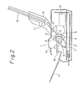
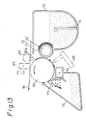
- FIG. 2 illustrates a structure of a printer according to a first embodiment of the present invention.
- the printer 1 is provided with a photoconductive drum 2 and a series of image-forming elements including a precharger 3, a latent image-forming means 4, such as an LED array, a developer 5, a transfer-charger 9, a discharger 6, and a cleaner 7 arranged around the surface of the drum 2.
- a fuser 14 is disposed on the left of the transfer-charger 9 in Fig. 2.
- a medium 10 in a cut sheet form is accommodated in a hopper 8 and removed therefrom one by one by the rotation of a pickup roller 11 pressing against the cut sheets 10, and sent toward a regist roller 12.
- the medium cut sheets 10 are then kept in a standby position while in contact with the regist roller 12, until a command to commence to printing operation is output from a control unit (not shown).
- the photoconductive drum 2 Upon receiving the commence printing command, the photoconductive drum 2 is made to rotate in the arrowed direction, and the cut sheets 10 delivered from the regist roller 12 through a path 13 are introduced into an operational area of the transfer-charger 9 by a guide roller 15, in synchronism with the rotation of the drum 2.
- the photoconductive drum 2 is uniformly charged by the precharger 3, then a static latent image is formed by the LED array 4, which is developed by the developer 5 and transferred onto the cut sheet 10 by the transfer- charger 9.
- the cut sheet 10 is conveyed to the left in Fig. 2 toward the fuser 14, in which the toner image is fixed on the cut sheet 10, and finally the cut sheet 10 is discharged onto a stacker 17 by the eject roller 16.
- the charge on the surface of the photoconductive drum 2 is removed by the discharger 6 and residual toner powder is withdrawn by the cleaner 7.
- a reversible motor 19 is provided in the printer 1 as a common drive source for the respective rotating elements, which is selectively rotatable in the normal direction and the reverse direction in accordance with a command output by the control unit.
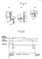
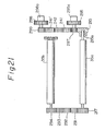
- the pickup roller 11 has a gear G12 at one end of a shaft 11a thereof and a one-way clutch 20a of the conventional type, which transmits a torque derived from the motor 19 to the shaft 11a only when the gear G12 rotates in the direction shown by a dotted line and shuts off the torque when rotated in the direction shown by a solid line.
- Figure 4(b) and 4(c) are similar views to Fig. 4(a), of the regist roller 12 and the photoconductive drum 2, respectively.
- a torque from the motor 19 is transmitted to the one-way clutch 20a via a gear train G12, G11, G10, G9, G8, G7, G6′, G6, G5′, G5, G4, G1, and 19b.
- the regist roller 12, which nips the cut sheet 10, in association with a pinch roller 12a, delivered by the pickup roller 11 has a gear G8 at one end of the shaft thereof, and another one-way clutch 20b, which transmits a torque derived from the motor 19 to the shaft 12b only when the gear G8 rotates in the direction shown by a solid line and inhibits the torque transmission when the gear G8 rotates in the reverse direction as shown by a dotted line.
- the latter rotation of the gear G8 corresponds to the counterclockwise rotation of the motor 19, by which the pickup roller 11 is operated.
- the photoconductive drum 2 is driven by a gear G secured to a shaft 2a, which gear G is, in turn, is driven by the motor 19 through a gear train G3, a third one-way clutch 20c, G3′, G2′ and G2 and G1.
- a sleeve and an agitator (not shown) in the developer 5 are also driven by a branch of this gear train.
- the one-way clutch 20c is adapted to transmit a torque only when the motor 19 is made to rotate clockwise.
- a heat roller 14 in the fuser which nips, in association with a backup roller 14a, the cut sheet 10 for fixing a toner image on the cut sheet, has a gear G14 at one end of the shaft thereof and a one-way clutch 20d.
- the gear 14 is related to a gear G6′ via a gear train G15, G16, G17, G18.
- the eject roller 16 has a gear G19 at one end of The shaft thereof, and a one-way clutch 20e.
- the gear G19 is related to a gear G16 through a gear train G20, G21.
- the one-way clutches 20d and 20e are adapted to transmit a torque to the associated shafts only when the motor 19 is rotated clockwise.
- An entry sensor 41 is provided for detecting the arrival of the cut sheet 10 at the standby position in front of the regist roller 12, and an exit sensor 42 is provided for detecting the discharger of the cut sheet 10 from the printing zone by the eject roller 16.
- Figure 5 shows a time chart for transporting the cut sheets 10.
- one cut sheet 10 in the hopper 8 is removed by the rotation of the pickup roller 11 caused by the rotation of the motor 19 in the normal direction and reaches the regist roller 12, this arrival is detected by the entry sensor 41.
- the motor 19 is made to rotate in the reverse direction by a command output by a control unit, and thus a printing operation is carried out on the cut sheet 10.
- the exit sensor 42 detects the discharge of the cut sheet 10
- the motor 19 made to stop after a period T2 from the detection of the discharge of the cut sheet 10 and waits for a command to commence the next cycle.
- the periods T1 and T2 are necessary fo enhancing the reliability of the operation.
- a printer according to this embodiment has a basic structure similar to that of the first embodiment described above, and the functions of the individual elements composing the printer are already known, the explanation will be made only of the difference of the second embodiment from the first embodiment.
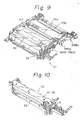
- the printer of the second embodiment has the appearance as shown in Fig. 6, and comprises a clam type housing having an upper frame unit 31 and a lower cover unit 32 detachably connected to each other by a hinge, as shown in Fig. 7.
- reference numeral 62 designates a control panel for controlling the operation of the printer and 63 designates a stacker for receiving a printed medium (cut sheets).
- the upper frame unit 31 has a fuser unit 36, a cooling fan 40, an entry sensor 41, an exit sensor 42 and a transfer-charger 43.
- first and second hoppers 33a and 33b are detachably secured to the upper frame unit 31.
- the hoppers 33a and 33b are provided, respectively, with pickup rollers 34a, 34b, which correspond, respectively, to regist rollers 35a, 35b secured to the upper frame unit 31.
- Different kinds of cut sheets 10 can be accommodated in these hoppers, respectively.
- either one of the hoppers is selected by the action of magnetic clutches 295a, 298a as stated later.
- a heat roller 37, a backup roller 38, and an eject roller 39 are all incorporated into the fuser unit 36.
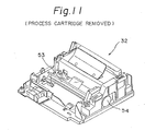
- a process cartridge 52 As illustrated in Figs. 7, 8 and 10, in the lower cover unit 32 are secured a process cartridge 52, and LED array 53, and a reversible motor 54 which is a drive source for the rotating elements of the printer.
- the process cartridge 52 is a composite body in which a developer consisting of a toner vessel 70, an agitator 71, and a developing roller 72, a precharger 74, a cleaning blade 73, a residual toner withdrawal vessel 75 and photoconductive drum 55 are integrally and compactly combined.
- the cartridge 52 is easily attached to and detached from the lower cover unit 32 by a push button mechanism.
- a toner powder in the vessel 70 is stirred by the agitator 71 and uniformly fed to the developing roller 72.
- the developing roller 72 consists of a magnetic roller 76 forming a core and of a sleeve 77 covered thereon.
- the magnetic roller 76 and the sleeve 77 rotate, respectively, at different speeds, so that the sleeve 77 can convey a toner powder onto the surface of the photoconductive drum 55 by a magnetic brush formed on the surface of the sleeve 77, which toner powder forms a toner image on the drum 55 corresponding to a latent image.
- the cleaning blade 73 is adapted to clean residual toner powder from the surface of the photoconductive drum 55 after the toner is transferred to the cut sheets 10.
- the precharger 74 is adapted to uniformly impart an electric charge to the surface of the photoconductive drum 55, to prepare for the next image forming cycle.
- An upper surface 52′ of the process cartridge 52 constitutes a guide plate for the cut sheets 10.
- a pinch roller 60a is provided at a front edge of the upper surface 52′ and biased upward by a blade spring 52a to be resiliently in contact with a guide roller 60 secured on the upper frame unit 31.
- the cut sheet 10 can be introduced into an image-transfer zone formed between the drum 55 and a transfer- charger 43, while nipped between the pinch roller 60a and the guide roller 60.
- a torque from the motor 54 is transmitted to the respective rotating elements in the lower cover unit 32 and the upper frame unit 31 through a gear box secured on one side of the lower cover unit.
- Figure 14 shows the gear box with the cover removed therefrom, in which various gears and pulleys are secured on a bracket 90.
- the torque from the motor 54 is transmitted to a gear 162 from a motor gear 110.
- a gear 163 is coaxially secured with the gear 162, with the intervention of a one-way clutch 162a of the known spring type, so that only the counter-clockwise rotation of the gear 162 can be transmitted to the gear 163.
- a one-way clutch 151a of the same type as the clutch 161a is intervened between a pulley 149 and a gear 151 secured coaxially therewith, which transmits only the counter-clockwise rotation of the pulley 149 to the gear 151.
- the gear 151 is used for driving the photoconductive drum 55 in the process cartridge 52 and is biased about a shaft A in the arrowed direction by a spring (not shown).
- a gear 170 is used for driving a developing roller 72 and is biased about a shaft B in the arrowed direction.
- a gear 161 is used for transmitting a torque to a gear train for driving the rollers secured in the upper frame unit 31 and is biased about a shaft C by a spring 80.
- These three gears 151, 170, and 161 are key wheels for outputting a torque from the gear box.
- Gears 161, 180 fixed coaxially with each other are rotatably secured at one end of a U-shaped member 93.
- the member 93 is rotatably secured at a middle portion thereof on the shaft C of a gear 179 intermeshed with the gear 180.
- the shaft C is rotatably secured on the bracket 90.
- a pin 94 is provided at the other end of the member 93 opposite to the gear 91, which extends backward through an aperture 95 of the bracket 90.
- the spring 80 also see Fig.
- the rotation of the motor gear 110 drives the gear 151 in the arrowed direction through a path of the gear 174, a pulley 175, a belt 49, and the pulley 149.
- a pulley/belt mechanism is used for driving the gear 151 so that the photoconductive drum can be smoothly rotated, resulting in a better printing quality.
- the rotating elements in the process cartridge 52 can be driven only when the motor is rotated clockwise, and are not driven when the motor is rotated counter-clockwise.
- a mechanism for driving the process cartridge 52 is explained in more detail with reference to Figs. 12, 13 and 17.
- gears L through Q for driving the process cartridge 52 are shown in Figs. 17(a) and (b), these gears are also illustrated in Fig. 12(a) in a simplified manner.
- a gear L is fixedly secured at one end of the sleeve 77, and a gear Q is fixedly secured at one end of the magnetic roller 76.
- a gear M consists of three gears M1, M2, M3 coaxially and integrally fixed with each other and a gear N consists of two gears N1 and N2 also coaxially and integrally fixed with each other.
- the gear M1 is intermeshed with the gear 170 in the gear box and transmits the rotation thereof through the gear B2 to the gear Q, which then drives the magnet roller 76.
- the rotation of the gear M2 is transmitted through a gear train M3, N1, N2, P to the gear L, which then drives the sleeve 77.
- the gears M, N, P are rotatably secured on a side wall of the process cartridge 52.
- a gear G fixed at the opposite end of the magnetic roller 76 is intermeshed with a gear F fixed at one end of a shaft of the agitator 71, to drive the latter.
- a gear 281 disposed at a center of the gear train is intermeshed with the gear 161 in the gear box of the lower cover unit 32.
- a torque is transmitted through a gear train 237, 282, 286 to a gear 287, which is intermeshed with a gear R (Fig. 10) fixed on a shaft of the heat roller 37 of the fuser, to drive the same.
- the gears 286 and 287 are secured coaxially with a one-way clutch 287a intervened therebetween, which is adapted to transmit only the clockwise rotation of the gear 286 to the gear 287. Accordingly, the heat roller 37 can rotate only counter-clockwise, to forward the cut sheets 10.
- the gear 286 further transmits a torque to a gear 211 for driving the eject roller 39 through a gear train 283 284, 285a or 285b, and 278.
- the gear 285a is secured at one end of an L-shaped lever 285 which, in turn, is pivoted about an axis X coaxially with the gear 284.
- a gear 285b having the same number of teeth as the gear 285a.
- the guide roller 60 is made to rotate by the gear 237.
- a torque from the motor is transmitted to a gear 215 secured at one end of a shaft of the regist roller 35a for the first hopper 33 via a one-way clutch 215a.
- the one-way clutch 215a is adapted to prevent a rotation of the gear 215 in the direction for driving the pickup roller 11 from being transmitted to the regist roller 35a but to permit the transmission of the opposite rotation of the gear 215 to the regist roller 35a to transport the cut sheets 10.
- a gear 217 which is associated with a gear 294 fixed at one end of the regist roller 35b for the second hopper 33b via a gear train 291, 292 and 293.
- both the regist rollers 35a, 35b are made to rotate simultaneously with each other.
- a press roller (not shown) for nipping the cut sheets in association with the regist roller 35a, 35b is provided adjacent to the respective regist rollers 35a, 35b and is made to rotate by the latter through a gear-engagement therewith.
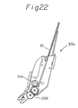
- the gear 215 is also intermeshed with a gear 297 coaxially fixed with a gear 295 having a magnetic clutch 295a and is associated with a gear 299 coaxially fixed with a gear 298 having a magnetic clutch 298a.
- the gear 295 is provided for engagement with a hopper gear 296 in the first hopper 33a, as shown in Fig. 22, and transmits the rotation to the latter when the magnetic clutch 295a is actuated so that the pickup roller 34a is made to rotate.
- the pickup roller 34b in the second hopper 33b is driven when the magnetic clutch 298a is actuated.
- the operation is basically similar to that of the first embodiment, but since a plurality of hoppers are provided in the second embodiment, the selection of the hopper must be made first by actuating one of the magnetic clutches. If the hopper 33a is selected, the magnetic clutch 295a is actuated so that the transmission path to the hopper 33a is formed. Of course, the other magnetic clutch 298a is off. Then the motor 54 is made to rotate in the direction whereby the pickup roller 34a is driven to forward the cut sheets 10, as shown in Fig. 23(a). When the front edge of the cut sheet 10 is detected by the entry sensor 41, the magnet clutch 295a is made off and then the motor 54 is stopped.
- the motor 54 When the next command is output, the motor 54 is rotated in the opposite direction, whereby the rotating elements in the printer other than pickup rollers 34a, 34b are driven in the arrowed direction in Fig. 23(b).
- the cut sheet 10 passes the upper surface of the photoconductive drum 55, and when the rear edge of the cut sheet 100 is detected by the exit sensor 42, the motor is stopped and waits for the command to commence the next printing.
- the printer since a single reversible motor is adopted for driving the respective rotating elements in the printer, and the normal and reverse rotations of the motor are separately used for driving a pickup roller and other rotating elements, respectively, by the intervention of a one-way clutch in a transmission path, the printer had a simple structure and small size.
- the printer housing is a clam type formed by an upper frame unit and a lower cover unit, which are detachably connected by a hinge. Rollers for running cut sheets are accommodated in the upper frame unit and a motor and a gear box are accommodated in the lower cover unit.
- the connection between the rollers and the motor through the gear box is completely cut, so that the rollers can be easily rotated by hand when clearing a jam.
Landscapes
- Physics & Mathematics (AREA)
- General Physics & Mathematics (AREA)
- Electrophotography Configuration And Component (AREA)
- Paper Feeding For Electrophotography (AREA)
Applications Claiming Priority (2)
| Application Number | Priority Date | Filing Date | Title |
|---|---|---|---|
| JP246716/87 | 1987-09-30 | ||
| JP24671687 | 1987-09-30 |
Publications (3)
| Publication Number | Publication Date |
|---|---|
| EP0314536A2 true EP0314536A2 (fr) | 1989-05-03 |
| EP0314536A3 EP0314536A3 (fr) | 1991-05-02 |
| EP0314536B1 EP0314536B1 (fr) | 1993-12-15 |
Family
ID=17152585
Family Applications (1)
| Application Number | Title | Priority Date | Filing Date |
|---|---|---|---|
| EP88402491A Expired - Lifetime EP0314536B1 (fr) | 1987-09-30 | 1988-09-30 | Appareil électrostatique de formation d'images |
Country Status (4)
| Country | Link |
|---|---|
| US (1) | US4967239A (fr) |
| EP (1) | EP0314536B1 (fr) |
| CA (1) | CA1324912C (fr) |
| DE (1) | DE3886350T2 (fr) |
Cited By (11)
| Publication number | Priority date | Publication date | Assignee | Title |
|---|---|---|---|---|
| EP0345089A3 (en) * | 1988-06-03 | 1990-12-27 | Fujitsu Limited | Image formation apparatus |
| EP0399565A3 (fr) * | 1989-05-26 | 1991-06-12 | Seiko Epson Corporation | Appareil d'impression |
| EP0416634A3 (en) * | 1989-09-08 | 1992-01-15 | Tokyo Electric Co., Ltd. | A paper feeder for page printer |
| EP0473180A3 (en) * | 1990-08-31 | 1992-03-18 | Canon Kabushiki Kaisha | Image forming apparatus |
| FR2675597A1 (fr) * | 1991-04-17 | 1992-10-23 | Samsung Electronics Co Ltd | Unite de traitement d'electrophotographie. |
| US5192067A (en) * | 1989-09-08 | 1993-03-09 | Tokyo Electric Co., Ltd. | Paper feed for page printer |
| EP0586033A3 (fr) * | 1992-06-30 | 1994-04-06 | Canon Kabushiki Kaisha | Tambour photosensible, cartouche de traitement, appareil et système de formation d'images |
| GB2278087A (en) * | 1993-04-28 | 1994-11-23 | Canon Kk | Gear unit,image forming apparatus and gear unit mounting method |
| EP0622698A3 (fr) * | 1993-04-28 | 1995-10-04 | Canon Kk | Tambour photosensible, unité de traitement et appareil de formation d'images. |
| EP1394624A1 (fr) * | 2002-08-30 | 2004-03-03 | Oki Data Corporation | Appareil de formation d'image avec dispositif de detection de l'image de toner |
| EP1209543B1 (fr) * | 2000-11-22 | 2008-07-02 | Ricoh Company, Ltd. | Méthode et dispositif de formation d'images avec procédé de fixation amélioré |
Families Citing this family (11)
| Publication number | Priority date | Publication date | Assignee | Title |
|---|---|---|---|---|
| KR0132039B1 (ko) * | 1993-05-24 | 1998-10-01 | 김광호 | 전자사진 현상방식 프린터의 잼 제거방법 |
| JPH07304233A (ja) * | 1994-05-16 | 1995-11-21 | Minolta Co Ltd | プリンタ装置 |
| KR100242296B1 (ko) * | 1997-08-30 | 2000-02-01 | 윤종용 | 전자사진 프로세서의 양면인쇄 구동장치 |
| JP4562017B2 (ja) * | 2000-07-13 | 2010-10-13 | 株式会社リコー | 像担持体回転制御装置、像担持体回転制御方法、および画像形成装置 |
| US7306216B2 (en) * | 2002-12-30 | 2007-12-11 | Samsung Electronics Co., Ltd. | Power transmitting apparatus, power switching apparatus, and driving apparatus of multi-function machine using the same |
| US7530559B2 (en) * | 2006-04-12 | 2009-05-12 | Hewlett-Packard Development Company, L.P. | Booklet maker |
| JP2008134556A (ja) * | 2006-11-29 | 2008-06-12 | Oki Data Corp | 画像形成装置 |
| JP5171869B2 (ja) * | 2010-03-31 | 2013-03-27 | 京セラドキュメントソリューションズ株式会社 | 駆動機構及びそれを備えた画像形成装置 |
| JP5577824B2 (ja) * | 2010-04-27 | 2014-08-27 | ブラザー工業株式会社 | 画像形成装置 |
| JP2014191106A (ja) * | 2013-03-26 | 2014-10-06 | Fuji Xerox Co Ltd | 画像形成装置および像保持体 |
| JP6387854B2 (ja) * | 2015-02-23 | 2018-09-12 | ブラザー工業株式会社 | 画像形成装置 |
Family Cites Families (8)
| Publication number | Priority date | Publication date | Assignee | Title |
|---|---|---|---|---|
| US4264182A (en) * | 1979-05-10 | 1981-04-28 | Eastman Kodak Company | Electrographic apparatus having improved development structure |
| US4652161A (en) * | 1983-04-28 | 1987-03-24 | Wang Laboratories, Inc. | Sheet feeding apparatus |
| US4789259A (en) * | 1986-01-13 | 1988-12-06 | Canon Kabushiki Kaisha | Cut sheet feed apparatus |
| JPS62177563A (ja) * | 1986-01-30 | 1987-08-04 | Toshiba Corp | 画像形成装置 |
| DE3784261T2 (de) * | 1986-04-04 | 1993-06-09 | Seiko Epson Corp | Geraet zum erzeugen eines bildes auf einem papierblatt. |
| JPS63210858A (ja) * | 1987-02-27 | 1988-09-01 | Toshiba Corp | 画像形成装置 |
| US4727387A (en) * | 1987-06-24 | 1988-02-23 | Blaser Industries, Inc. | Paper-handling mechanism for laser printer |
| CA1327831C (fr) * | 1988-05-25 | 1994-03-15 | Shigeki Sakakura | Appareil de formation d'images |
-
1988
- 1988-09-28 CA CA000578665A patent/CA1324912C/fr not_active Expired - Fee Related
- 1988-09-30 EP EP88402491A patent/EP0314536B1/fr not_active Expired - Lifetime
- 1988-09-30 DE DE88402491T patent/DE3886350T2/de not_active Expired - Lifetime
-
1990
- 1990-01-23 US US07/467,357 patent/US4967239A/en not_active Expired - Lifetime
Cited By (20)
| Publication number | Priority date | Publication date | Assignee | Title |
|---|---|---|---|---|
| EP0345089A3 (en) * | 1988-06-03 | 1990-12-27 | Fujitsu Limited | Image formation apparatus |
| EP0399565A3 (fr) * | 1989-05-26 | 1991-06-12 | Seiko Epson Corporation | Appareil d'impression |
| US5141222A (en) * | 1989-05-26 | 1992-08-25 | Seiko Epson Corporation | Process including multiple sheet discharge printer using electrophotographic receivers with a pivotal sorter guide |
| EP0416634A3 (en) * | 1989-09-08 | 1992-01-15 | Tokyo Electric Co., Ltd. | A paper feeder for page printer |
| US5192067A (en) * | 1989-09-08 | 1993-03-09 | Tokyo Electric Co., Ltd. | Paper feed for page printer |
| US5528343A (en) * | 1990-08-31 | 1996-06-18 | Canon Kabushiki Kaisha | Driving cartridge for an image forming apparatus |
| EP0473180A3 (en) * | 1990-08-31 | 1992-03-18 | Canon Kabushiki Kaisha | Image forming apparatus |
| FR2675597A1 (fr) * | 1991-04-17 | 1992-10-23 | Samsung Electronics Co Ltd | Unite de traitement d'electrophotographie. |
| EP0586033A3 (fr) * | 1992-06-30 | 1994-04-06 | Canon Kabushiki Kaisha | Tambour photosensible, cartouche de traitement, appareil et système de formation d'images |
| US5602623A (en) * | 1992-06-30 | 1997-02-11 | Canon Kabushiki Kaisha | Photosensitive drum provided in an image forming apparatus including gears disposed at an end of drum |
| EP0813119A1 (fr) * | 1992-06-30 | 1997-12-17 | Canon Kabushiki Kaisha | Tambour photosensible, cartouche de traitement, appareil et système de formation d'image |
| US5926672A (en) * | 1992-06-30 | 1999-07-20 | Canon Kabushiki Kaisha | Photosensitive drum provided in an image forming apparatus including helical gears disposed at an end of the drum |
| GB2278087A (en) * | 1993-04-28 | 1994-11-23 | Canon Kk | Gear unit,image forming apparatus and gear unit mounting method |
| EP0622698A3 (fr) * | 1993-04-28 | 1995-10-04 | Canon Kk | Tambour photosensible, unité de traitement et appareil de formation d'images. |
| GB2278087B (en) * | 1993-04-28 | 1996-07-31 | Canon Kk | Electrophotographic image forming apparatus |
| US5634178A (en) * | 1993-04-28 | 1997-05-27 | Canon Kabushiki Kaisha | Gear unit, image forming apparatus and gear unit mounting method |
| US5825472A (en) * | 1993-04-28 | 1998-10-20 | Canon Kabushiki Kaisha | Photosensitive drum, process cartridge and image forming apparatus |
| EP1209543B1 (fr) * | 2000-11-22 | 2008-07-02 | Ricoh Company, Ltd. | Méthode et dispositif de formation d'images avec procédé de fixation amélioré |
| EP1394624A1 (fr) * | 2002-08-30 | 2004-03-03 | Oki Data Corporation | Appareil de formation d'image avec dispositif de detection de l'image de toner |
| US7020404B2 (en) | 2002-08-30 | 2006-03-28 | Oki Data Corporation | Image forming apparatus with color shift sensors that are shielded from toner |
Also Published As
| Publication number | Publication date |
|---|---|
| DE3886350D1 (de) | 1994-01-27 |
| EP0314536A3 (fr) | 1991-05-02 |
| CA1324912C (fr) | 1993-12-07 |
| DE3886350T2 (de) | 1994-03-31 |
| EP0314536B1 (fr) | 1993-12-15 |
| US4967239A (en) | 1990-10-30 |
Similar Documents
| Publication | Publication Date | Title |
|---|---|---|
| EP0314536B1 (fr) | Appareil électrostatique de formation d'images | |
| EP0348256B1 (fr) | Appareil de formation d'images | |
| US5047803A (en) | Image forming apparatus with detachably mountable process cartridge | |
| US4977428A (en) | System for drive control of toner agitator in image-forming apparatus | |
| EP0372294B1 (fr) | Mécanisme d'alimentation du papier | |
| US20040145112A1 (en) | Sheet delivery mechanism for image forming apparatus | |
| EP0400956B1 (fr) | Imprimante/copieur recto-verso | |
| US6950622B2 (en) | Manual paper feeding apparatus | |
| US8254824B2 (en) | Recording medium conveying device and image forming apparatus | |
| JP3347922B2 (ja) | 複写機 | |
| JPS60150073A (ja) | 像形成装置 | |
| US5162852A (en) | Image forming apparatus having exchangeable developing device | |
| EP0155357B1 (fr) | Procédé de production d'images | |
| JPH08225210A (ja) | 画像形成装置 | |
| JPH01156252A (ja) | プリンタ | |
| JP2002003046A (ja) | 画像形成装置 | |
| JP3913317B2 (ja) | 画像形成装置 | |
| JP2864971B2 (ja) | 両面印刷装置 | |
| JP2001002282A (ja) | シート搬送装置および画像形成装置 | |
| JP2583950B2 (ja) | 定着装置 | |
| JPH10203659A (ja) | 給紙装置 | |
| JPH03284554A (ja) | 用紙給送装置 | |
| JPH03232630A (ja) | 用紙送り機構 | |
| JPH08129319A (ja) | 画像形成装置 | |
| JPH10207156A (ja) | 画像形成装置 |
Legal Events
| Date | Code | Title | Description |
|---|---|---|---|
| PUAI | Public reference made under article 153(3) epc to a published international application that has entered the european phase |
Free format text: ORIGINAL CODE: 0009012 |
|
| AK | Designated contracting states |
Kind code of ref document: A2 Designated state(s): DE FR GB SE |
|
| PUAL | Search report despatched |
Free format text: ORIGINAL CODE: 0009013 |
|
| AK | Designated contracting states |
Kind code of ref document: A3 Designated state(s): DE FR GB SE |
|
| 17P | Request for examination filed |
Effective date: 19910927 |
|
| 17Q | First examination report despatched |
Effective date: 19920721 |
|
| GRAA | (expected) grant |
Free format text: ORIGINAL CODE: 0009210 |
|
| AK | Designated contracting states |
Kind code of ref document: B1 Designated state(s): DE FR GB SE |
|
| REF | Corresponds to: |
Ref document number: 3886350 Country of ref document: DE Date of ref document: 19940127 |
|
| ET | Fr: translation filed | ||
| PLBE | No opposition filed within time limit |
Free format text: ORIGINAL CODE: 0009261 |
|
| STAA | Information on the status of an ep patent application or granted ep patent |
Free format text: STATUS: NO OPPOSITION FILED WITHIN TIME LIMIT |
|
| 26N | No opposition filed | ||
| EAL | Se: european patent in force in sweden |
Ref document number: 88402491.0 |
|
| PGFP | Annual fee paid to national office [announced via postgrant information from national office to epo] |
Ref country code: SE Payment date: 19950918 Year of fee payment: 8 |
|
| PG25 | Lapsed in a contracting state [announced via postgrant information from national office to epo] |
Ref country code: SE Effective date: 19961001 |
|
| EUG | Se: european patent has lapsed |
Ref document number: 88402491.0 |
|
| REG | Reference to a national code |
Ref country code: GB Ref legal event code: IF02 |
|
| REG | Reference to a national code |
Ref country code: GB Ref legal event code: 732E |
|
| REG | Reference to a national code |
Ref country code: FR Ref legal event code: TP |
|
| PGFP | Annual fee paid to national office [announced via postgrant information from national office to epo] |
Ref country code: DE Payment date: 20070927 Year of fee payment: 20 |
|
| PGFP | Annual fee paid to national office [announced via postgrant information from national office to epo] |
Ref country code: GB Payment date: 20070926 Year of fee payment: 20 |
|
| PGFP | Annual fee paid to national office [announced via postgrant information from national office to epo] |
Ref country code: FR Payment date: 20070914 Year of fee payment: 20 |
|
| REG | Reference to a national code |
Ref country code: GB Ref legal event code: PE20 Expiry date: 20080929 |
|
| PG25 | Lapsed in a contracting state [announced via postgrant information from national office to epo] |
Ref country code: GB Free format text: LAPSE BECAUSE OF EXPIRATION OF PROTECTION Effective date: 20080929 |