EP0315041A2 - Vakuum-Rotationstrockner - Google Patents
Vakuum-Rotationstrockner Download PDFInfo
- Publication number
- EP0315041A2 EP0315041A2 EP88117862A EP88117862A EP0315041A2 EP 0315041 A2 EP0315041 A2 EP 0315041A2 EP 88117862 A EP88117862 A EP 88117862A EP 88117862 A EP88117862 A EP 88117862A EP 0315041 A2 EP0315041 A2 EP 0315041A2
- Authority
- EP
- European Patent Office
- Prior art keywords
- shell body
- shell
- charge
- air
- hot water
- Prior art date
- Legal status (The legal status is an assumption and is not a legal conclusion. Google has not performed a legal analysis and makes no representation as to the accuracy of the status listed.)
- Granted
Links
- 239000000463 material Substances 0.000 claims abstract description 36
- 238000002156 mixing Methods 0.000 claims abstract description 32
- XLYOFNOQVPJJNP-UHFFFAOYSA-N water Substances O XLYOFNOQVPJJNP-UHFFFAOYSA-N 0.000 claims abstract description 31
- 239000012530 fluid Substances 0.000 claims abstract description 17
- 238000001035 drying Methods 0.000 description 17
- 239000007788 liquid Substances 0.000 description 14
- 239000013590 bulk material Substances 0.000 description 6
- 238000005469 granulation Methods 0.000 description 5
- 230000003179 granulation Effects 0.000 description 5
- 239000000654 additive Substances 0.000 description 4
- 238000005516 engineering process Methods 0.000 description 4
- 239000000843 powder Substances 0.000 description 4
- 239000007921 spray Substances 0.000 description 4
- 239000011248 coating agent Substances 0.000 description 3
- 238000000576 coating method Methods 0.000 description 3
- 230000015556 catabolic process Effects 0.000 description 2
- 238000004891 communication Methods 0.000 description 2
- 238000006731 degradation reaction Methods 0.000 description 2
- 239000011521 glass Substances 0.000 description 2
- 238000010438 heat treatment Methods 0.000 description 2
- 238000003780 insertion Methods 0.000 description 2
- 230000037431 insertion Effects 0.000 description 2
- 238000000034 method Methods 0.000 description 2
- 238000003908 quality control method Methods 0.000 description 2
- 238000005979 thermal decomposition reaction Methods 0.000 description 2
- 238000001291 vacuum drying Methods 0.000 description 2
- 229910000975 Carbon steel Inorganic materials 0.000 description 1
- 230000000996 additive effect Effects 0.000 description 1
- 239000010962 carbon steel Substances 0.000 description 1
- 239000006185 dispersion Substances 0.000 description 1
- 238000010981 drying operation Methods 0.000 description 1
- 230000002349 favourable effect Effects 0.000 description 1
- 210000004907 gland Anatomy 0.000 description 1
- 230000001788 irregular Effects 0.000 description 1
- 239000000203 mixture Substances 0.000 description 1
- 238000012856 packing Methods 0.000 description 1
- 239000002245 particle Substances 0.000 description 1
- 238000012545 processing Methods 0.000 description 1
- 239000002994 raw material Substances 0.000 description 1
- 239000010935 stainless steel Substances 0.000 description 1
- 229910001220 stainless steel Inorganic materials 0.000 description 1
Images





Classifications
-
- F—MECHANICAL ENGINEERING; LIGHTING; HEATING; WEAPONS; BLASTING
- F26—DRYING
- F26B—DRYING SOLID MATERIALS OR OBJECTS BY REMOVING LIQUID THEREFROM
- F26B11/00—Machines or apparatus for drying solid materials or objects with movement which is non-progressive
- F26B11/02—Machines or apparatus for drying solid materials or objects with movement which is non-progressive in moving drums or other mainly-closed receptacles
- F26B11/04—Machines or apparatus for drying solid materials or objects with movement which is non-progressive in moving drums or other mainly-closed receptacles rotating about a horizontal or slightly-inclined axis
- F26B11/049—Machines or apparatus for drying solid materials or objects with movement which is non-progressive in moving drums or other mainly-closed receptacles rotating about a horizontal or slightly-inclined axis with provisions for working under increased or reduced pressure, with or without heating
-
- F—MECHANICAL ENGINEERING; LIGHTING; HEATING; WEAPONS; BLASTING
- F26—DRYING
- F26B—DRYING SOLID MATERIALS OR OBJECTS BY REMOVING LIQUID THEREFROM
- F26B11/00—Machines or apparatus for drying solid materials or objects with movement which is non-progressive
- F26B11/02—Machines or apparatus for drying solid materials or objects with movement which is non-progressive in moving drums or other mainly-closed receptacles
- F26B11/04—Machines or apparatus for drying solid materials or objects with movement which is non-progressive in moving drums or other mainly-closed receptacles rotating about a horizontal or slightly-inclined axis
-
- F—MECHANICAL ENGINEERING; LIGHTING; HEATING; WEAPONS; BLASTING
- F26—DRYING
- F26B—DRYING SOLID MATERIALS OR OBJECTS BY REMOVING LIQUID THEREFROM
- F26B5/00—Drying solid materials or objects by processes not involving the application of heat
- F26B5/04—Drying solid materials or objects by processes not involving the application of heat by evaporation or sublimation of moisture under reduced pressure, e.g. in a vacuum
-
- F—MECHANICAL ENGINEERING; LIGHTING; HEATING; WEAPONS; BLASTING
- F26—DRYING
- F26B—DRYING SOLID MATERIALS OR OBJECTS BY REMOVING LIQUID THEREFROM
- F26B7/00—Drying solid materials or objects by processes using a combination of processes not covered by a single one of groups F26B3/00 and F26B5/00
Definitions
- the present invention relates to drying technology, mixing technology, and granulating technology of bulk material which belong to the international patent classification B 02, 05. More particularly it relates to a double cone type vacuum rotary dryer having a superior mixing function, especially for the mixing of bulk materials, which prevents the material from sticking to the inner wall surface of the dryer and also has a granulating function.
- this type of rotary vacuum dryer only serves for the drying operation and it has no mixing function (the term "mixing” used here implies the technologies for blending defferent types of bulk material, for coating on particles, and for granulation). It merely rotates the drying chamber to conduct drying.
- the pre-mixed bulk materials or liquids to be dried enter through a charge/discharge opening in the side wall of the drying chamber, and the dried products are discharged through the same opening.
- This type of dryer also has the disadvantage that powders in particular tend to stick to the inner wall surface of the drying chamber and are heated to an abnormally high temperature, leading to a dispersion of mixing ratio.
- the existing equipment only performs drying and has structurally no good mixing function. Regerding the drying function, it has the problems that materials stick to the inner wall surface and that the irregular temperature distribution on the inner wall surface results in uneven drying of the materials.
- the present invention has been made to cope with the aforesaid disadvantages, and the object of this invention is to present a vacuum rotary dryer which performs vacuum drying of bulk materials, preventing them from sticking to the inner wall surface, and which yields stable high quality products by low temperature vacuum drying without any thermal decomposition or any thermal degradation.
- Another object of this invention is to present a vacuum rotary dryer which can be used also as a mixer and which freely allows the addition of additive powders and liquids during the mixing operation under air-tight conditions, which allow uniform mixing.
- the further object of this invention is to present a butterfly valve which forms a charge/discharge opening suitable for the above illustrated operations.
- the vacuum rotary dryer in accordance with the present invention has a structure wherein a shell is supported by the bearing stand at the axial shaft which projects from one side of the shell on the horizontal center axis and the shell has an open/close air-tight closure on one side of the shell as a charge/discharge opening and the shell has a double structure comprising a jacket on the whole surface of the inner shell body to form a flow path of hot water/hot air, and wherein a mixing blade is mounted at a part of the inner wall surface of the shell body to be rotated by an outside drive mechanism, and wherein charge/discharge pipes communicate with the flow path of the hot water/hot air and are connected to the outside conduits, and wherein more than one charge pipe which charge bulk materials or fluids and a high pressure gas feed pipe and an evacuation pipe communicate with an outside vacuum unit are opened in the inside of the shell body through the axial shaft, and wherein an inserted pipe of the high pressure gas feed pipe is curved along the curvature of the inner wall of the shell body at a
- this equipment To use this equipment as a dryer or a granulator, the bulk materials to be processed are charged through the opened air-tight closure of the charge/discharge opening, and after the closure is realed the chamber is rotated by a rotary drive motor around the supported axial shaft to conduct the drying or granulating operation.
- hot water at an appropriate temperature is sent through the flow path for hot water/hot air on the outside surface of the shell body and on the air-tight closure via the hot water charge/discharge pipes to heat and dry the contained bulk materials through the walls of the shell body and the closure.
- the drying occurs in a vacuum and at a low temperature to produce high quality products free from thermal decomposition or thermal degradation.
- this equipment To use this equipment as a mixer, after the bulk materials to be mixed are charged through the opened air-tight closure of charge/discharge opening, the closure is sealed and the chamber is rotated by the rotary drive motor around the supported axial shaft and the mixing blade mounted on the inner wall surface of the shell body is rotated by a rotary drive mechanism such as an air-motor to conduct the mixing operation.
- the rotation of the shell body induces the repeated "press” and “disperse” motion of the bulk materials against the wall surface. This motion enhances the mixing by the rotary mixing blade.
- the jacketed concave part of the air-tight closure is covered with a blind plate and a fluid such as hot water is charged to the jacketed fluid path via feed pipe and is discharged from the discharge pipe, the hot water heats the blind plate which in turn heats the contacting materials inside the chamber of the shell body to achieve a uniform temperature distribution on the whole wall surface.
- This new vacuum rotary dryer in accordance with the present invention has the advantage that it can be used as a dryer or mixer or a dryer and mixer.
- Another advantage of this invention is that the addition of bulk materials and liquids during the mixing process is considerably simplified.
- a further advantage is that there is no sticking of bulk materials to the inner wall surface of the shell body during mixing or drying.
- a further advantage is that it achieves excellent quality control because there is no opening of the closure when charging additives.
- a further advantage of this invention is that it can be used as a multi-functional piece of equipment for granulation, liquid addition, coating, and other operations because it mixes different types of bulk materials and liquids and it can add and mix them during the drying process.
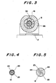
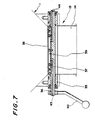
- Fig. 1 through Fig. 7 illustrate the first embodiment of this invention.
- Number 1 in the figures is the double structured shell which has the shell body 2 made of stainless steel or carbon steel or other materials as the inner structure and which has the jacket 3 at outside surface of the shell body 2 as the outer structure to form the flow path 4 between the shell body 2 and the jacket 3 for hot water/hot air and which has the charge/discharge opening 14 at a top of the conical shell and which has the air-tight closure 13 at the charge/discharge opening 14 in a manner to be easily opened or closed.
- the flange member 5a is mounted to penetrate the shell 1 to connect with the rotary tube shaft 5.
- the rotary tube shaft 5 which is extended with an air-tight device from the flange member 5a is supported to freely rotate on two bearings 6, 6 which are fixed on the base 7.
- the rotary tube shaft 5 or the extended part is connected to an appropriate rotary drive unit (not shown) to rotate the rotary tube shaft 5 according to a predetermined program.
- Number 8 in the figures is the observation hole in the shell 1 at one end of the rotating center axis.
- the observation hole 8 is formed by mounting a transparent hard glass plate 10 in a cylindrical frame 9 which penetrates the shell body 2 and the jacket 3 so that the fixture is air-tight.
- a feeder pipe 16 is inserted in a manner that the feeder pipe 16 freely rotates under air-tight conditions using a shaft seal mechanism 15 such as gland packings.
- the stick-proof air nozzle 23 is curved along the curvature of the inner wall of the shell body 2 at a certain distance and has many small holes 25, 25... along the line of the outer side of the curvature to form a circular arc, with the configuration of the air nozzle 23, the jetted air from many small holes 25, 25... blows off any bulk materials which stick to the inner wall surface of the shell body 2.
- Number 26 in the figures is the rotary joint pipe which sheathes the extended part of the rotary tube shaft 5 under air-tight and rotational conditions and which is provided with charge/discharge ports 27 and 28 for hot air or hot water to the jacket, the charge/discharge ports 29 and 30 for hot air or hot water to the air-tight closure 13, the gas charge/discharge ports 31 and 32 to the chopper, and the auxiliary port 33.
- the rotary joint 26 communicates with the hot water/hot air flow path 4 of the shell body 2 and the jacket on the air tight closure 13 via the corresponding communication paths 34 through the rotary tube shaft 5 under the rotating condition.
- the air-tight closure 13 opens and closes the charge/discharge opening 14 on the ring support frame 35.
- the rotary shaft 36 is attached to cross the ring support frame 35 at the center axis of the charge/discharge opening 14 under rotary and air-tight conditions.
- the closure plate 37 is attached to the rotary shaft to rotate approximately 90 degrees within the charge/discharge opening 14 and the closure plate 37 is provided with an 0-ring on the periphery thereof to construct air-tight inserted valve structure.
- the jacketed area 39 is formed with an arbitrarily perforated plate 38 mounted by small screws for easy removal.
- the fluid charge path 43 and the fluid discharge path 44 are provided to communicate with both ends of the rotary shaft 36 and the jacketed area 39.
- the charge/discharge ports 29 and 30 for hot air or hot water to the air-tight closure 13 communicate with the fluid paths 43 and 44 via the communication paths 34.
- Number 40 in the figures is the valve operating lever which is mounted at one end of the rotary shaft 36.
- Number 41 in the figures is the mixing blade which is mounted with an air-tight fitting from the outside of the shell 1 at a part of the inner wall of the shell body 2.
- the mixing blade 41 is driven by a rotary drive mechanism such as an airmotor 42 to break up the skinned agglomerates which are formed after the granulation upon the addition of liquid to the bulk materials or to disintegrate the skinned agglomerates which are formed after the drying of granulated materials by heating through the jacket or by hot air.
- the above illustrated vacuum rotary dryer dries or mixes the bulk materials by charging them into the shell body 2 through the charge/discharge opening 14 and by closing the air-tight closure 13 and by rotating or swinging the shell 1 with the rotary drive unit according to a predetermined program.
- the drying process is conducted with a supply of hot water or hot air to the hot water/hot air flow path 4 on the shell body 2 and to the jacketed area 39 on the air-tight closure 13 via the charge/discharge ports 27 and 28 for hot air or hot water to the jacket and via the charge/discharge ports for hot air or hot water to the air-tight closure 13.
- mixing or granulation is conducted while the additional fluids or powders are charged into the inside as needed through the bulk material charge pipe 12, the evacuation pipe 18, the liquid charge pipe 20, and the air supply pipe 24, or some combination of these pipes.
- the rotation of the shell body 2 induces a repeated "press” and “disperse” motion of the bulk materials against the wall surface. Tis motion enhances the mixing produced by the rotary motion by the mixing blade 41.
- Fig. 8 and Fig. 9 illustrate the second embodiment of this vacuum rotary dryer invention.
- the double structured shell 1 which has the shell body 2 as the inner structure and the jacket 3 on the outside surface of the shell body 2 as the outer structure to form the flow path 4 between the double structures for hot water/ hot air and which has the charge/discharge opening 14 at the bottom of the conical shell 1 and which has the air-tight closure 13 at the charge/discharge opening 14 in a manner to be easily opened and closed.
- the mixing blade 41 is air-tightly mounted with an air-tight fitting from the outside of the shell 1 at a part of the inner wall of the shell body 2.
- the mixing blade 41 is driven by a drive mechanism such as air-motor 42.
- the flange member 5a is mounted to penetrate the shell 1 to connect with the rotary tube shaft 5.
- the extended part of the rotary tube shaft 5 is horizontally supported on the bearing units mounted on the base (not shown) to rotate the tube shaft 5 following a predetermined program.
- the evacuating pipe 18 having an air filter 17 at one end is air-tightly inserted into the rotary tube shaft 5.
- the rotary frame 53 is mounted between the shell body 2 and the jacket 3.
- the rotary frame 53 rotates air-tightly inside the flange 52 which penetrates the jacket 3 and the shell body 2 to open the material charge opening 49 via the mechanical seal mechanism consisting of the bearing 45 and the oil seal 46.
- the material charge opening 49 has a cylindrical frame 9 which is opened or closed by the operation of the lock handles 50, 50 and has an observation hole 8 provided with a transparent hard glass plate 10 sealed air-tight into a cylindrical frame 9.
- the wiper 51 is attached to the observation hole 8.
- the following pipes are sealed air-tight to and pass through the flange 52 :
- the liquid charge pipe 20 which is provided with a spray nozzle 19 for liquid addition.
- the signal wire insertion pipe 22 which holds a signal cable to communicate with the temperature sensor 21 extended to the inside chamber of the shell body 2.
- the conduit 48 which communicates with the pressure gauge 47.
- the air supply pipe 24 which communicates with the stick-proof air nozzle 23.
- the air nozzle 23 is curved along the curvature of the inner wall of the shell body 2 at a certain distance to form a circular arc and has many small holes 25, 25... along the line of outer side of curvature to blow off any bulk materials stuck to the inner wall surface of the shell body 2 using the high pressure air jetted from the small holes 25.
- the vacuum rotary dryer having the described structure performs drying, granulation, and coating of bulk materials by charging the materials and additives through the material charge opening 49 and using the spray nozzle 19 for addition of liquids, and blows off bulk materials stuck to the inner wall surface of the shell body 2 using pressured air jetted from the stick-proof air nozzle 23 positioned against the inner wall of the shell body 2, and is automatically controlled using information output from the temperature sensor 21 and the pressure gauge 47.
- a vacuum rotary dryer provided with an air-tight closure having a jacket used for the through-flow or charging of fluid, and characterized by a structure comprising a shell having a charge/discharge opening provided with said air-tight closure being arbitrarily opened or closed, and comprising the double structure of said shell with an inside shell body and an outside jacket to form a hot water/hot air flow path between said shell body and said jacket, and comprising a drive motor to rotate said shell body via an axial shaft being projected from said shell body at the end of the horizontal center axis, and comprising a rotational mixing blade being mounted at a part of the inner wall of said shell body to be driven by a drive mechanism at need, and comprising the hot water/hot air charge/discharge pipes to communicate with said hot water/hot air flow path and with the outside source, and comprising more than one pipe to charge bulk materials or fluids, and a pipe to feed high pressure gas, and an evacuation pipe communicating with an outside vacuum unit, which pipes have ends opening into the inner chamber of said shell body and coming through
Landscapes
- Engineering & Computer Science (AREA)
- Mechanical Engineering (AREA)
- General Engineering & Computer Science (AREA)
- Health & Medical Sciences (AREA)
- Life Sciences & Earth Sciences (AREA)
- Molecular Biology (AREA)
- Drying Of Solid Materials (AREA)
- Vaporization, Distillation, Condensation, Sublimation, And Cold Traps (AREA)
Priority Applications (1)
| Application Number | Priority Date | Filing Date | Title |
|---|---|---|---|
| AT88117862T ATE87086T1 (de) | 1987-11-02 | 1988-10-26 | Vakuum-rotationstrockner. |
Applications Claiming Priority (4)
| Application Number | Priority Date | Filing Date | Title |
|---|---|---|---|
| JP16798687U JPH0349332Y2 (de) | 1987-11-02 | 1987-11-02 | |
| JP27759987 | 1987-11-02 | ||
| JP277599/87 | 1987-11-02 | ||
| JP1679/86U | 1987-11-02 |
Publications (3)
| Publication Number | Publication Date |
|---|---|
| EP0315041A2 true EP0315041A2 (de) | 1989-05-10 |
| EP0315041A3 EP0315041A3 (en) | 1990-06-27 |
| EP0315041B1 EP0315041B1 (de) | 1993-03-17 |
Family
ID=26491859
Family Applications (1)
| Application Number | Title | Priority Date | Filing Date |
|---|---|---|---|
| EP88117862A Expired - Lifetime EP0315041B1 (de) | 1987-11-02 | 1988-10-26 | Vakuum-Rotationstrockner |
Country Status (5)
| Country | Link |
|---|---|
| US (1) | US4916831A (de) |
| EP (1) | EP0315041B1 (de) |
| KR (1) | KR930006065B1 (de) |
| AT (1) | ATE87086T1 (de) |
| DE (1) | DE3879377T2 (de) |
Cited By (11)
| Publication number | Priority date | Publication date | Assignee | Title |
|---|---|---|---|---|
| EP0435305A3 (en) * | 1989-12-29 | 1991-09-25 | Maschinen Witte Gmbh & Co. Kg | Device for the drying of sludges, especially sewage sludges |
| EP0632241A1 (de) * | 1993-06-03 | 1995-01-04 | Dr. Karl Thomae GmbH | Eintopf-Mischer-Granulator-Trockner |
| EP1473532A2 (de) | 2003-01-13 | 2004-11-03 | Bernd Dreisbach | Rotations-Trocknungsanlage |
| CN103148682A (zh) * | 2013-03-13 | 2013-06-12 | 安徽省虹升生物科技有限公司 | 一种双锥形旋转烘干机 |
| CN103423975A (zh) * | 2013-08-30 | 2013-12-04 | 张家港市三联化工科技有限公司 | 用于dhppa的烘干装置 |
| CN103438673A (zh) * | 2013-08-22 | 2013-12-11 | 江苏美星大地环保科技有限公司 | 抽真空干燥机 |
| CN108692539A (zh) * | 2018-06-20 | 2018-10-23 | 南京汇龙橡胶制品有限公司 | 一种天然橡胶加工干燥装置 |
| CN116086137A (zh) * | 2023-02-09 | 2023-05-09 | 常州市步步干燥设备有限公司 | 一种回转式真空干燥机 |
| CN117404882A (zh) * | 2023-12-15 | 2024-01-16 | 常州市步步干燥设备有限公司 | 一种双锥回转式真空干燥机 |
| CN118361929A (zh) * | 2024-06-19 | 2024-07-19 | 江苏华普干燥工程有限公司 | 一种防结块的双锥真空干燥机及其工作方法 |
| CN119042957A (zh) * | 2024-10-31 | 2024-11-29 | 江苏金申医药科技有限公司 | 一种均匀加热的真空回转干燥机及其方法 |
Families Citing this family (26)
| Publication number | Priority date | Publication date | Assignee | Title |
|---|---|---|---|---|
| IT233918Y1 (it) * | 1994-01-25 | 2000-02-16 | C S S R L Coating System | Dispositivo di essiccazione per macchine confettatrici |
| JP3465735B2 (ja) * | 1995-10-02 | 2003-11-10 | 株式会社大井製作所 | 車両用スライドドアの自動開閉制御装置 |
| US6105272A (en) | 1998-06-22 | 2000-08-22 | Cabot Corporation | High temperature rotating vacuum kiln for heat treating solid particulate material under a vacuum |
| US6380517B2 (en) | 1999-06-21 | 2002-04-30 | Cabot Corporation | High temperature rotating vacuum kiln and method for heat treating solid particulate material under a vacuum |
| GB2461520A (en) | 2008-07-01 | 2010-01-06 | Magsnack Bv | Manufacturing crumb for the coating of food products |
| DE102009027790B4 (de) * | 2009-04-08 | 2017-05-18 | Dorfner Analysenzentrum Und Anlagenplanungs-Gesellschaft Mbh | Vorrichtung und Verfahren zum Reinigen von Quarzmaterial oder Silicium |
| US8765202B2 (en) | 2010-01-15 | 2014-07-01 | Crisp Sensation Holding S.A. | Coated stabilised microwave heated foods |
| US9326536B2 (en) | 2011-01-27 | 2016-05-03 | Crisp Sensation Holding S.A. | Production of microwaveable coated food products |
| US9326537B2 (en) | 2011-01-27 | 2016-05-03 | Crisp Sensation Holding S.A. | Microwaveable coated food product, and method and apparatus for the manufacture thereof |
| CN102168906B (zh) * | 2011-03-08 | 2012-07-25 | 常州先锋干燥设备有限公司 | 双锥回转真空干燥主机 |
| CN102288012A (zh) * | 2011-05-25 | 2011-12-21 | 烟台卓能电池材料有限公司 | 一种回转式微波真空干燥机 |
| CN103134277A (zh) * | 2011-11-23 | 2013-06-05 | 四川制药制剂有限公司 | 内附干燥剂贴附层的双锥回转真空干燥机 |
| CN103134278A (zh) * | 2011-11-23 | 2013-06-05 | 四川制药制剂有限公司 | 内附干燥剂贴附层的双锥回转炒药机 |
| US20130156925A1 (en) | 2011-12-20 | 2013-06-20 | Crisp Sensation Holding S.A. | Crumb manufacture |
| CN102564083B (zh) * | 2012-02-02 | 2015-04-01 | 常州市步步干燥设备有限公司 | 电加热双锥真空干燥机 |
| US9689611B2 (en) | 2014-08-20 | 2017-06-27 | Gencor Industries, Inc. | Locking cam stop |
| CN104329918A (zh) * | 2014-08-21 | 2015-02-04 | 安徽美腾特种电缆材料有限公司 | 一种一步法硅烷交联聚乙烯烘干系统 |
| US9782705B2 (en) | 2015-03-05 | 2017-10-10 | Gala Industries, Inc. | Tumbler systems and methods |
| US9689441B2 (en) | 2015-04-10 | 2017-06-27 | Gencor Industries, Inc. | Horizontal cam stop |
| CN106440713A (zh) * | 2016-08-15 | 2017-02-22 | 常州力马干燥科技有限公司 | 一种圆筒式真空喷雾干燥机 |
| CN107314643A (zh) * | 2017-06-12 | 2017-11-03 | 太仓市友联干燥粉碎设备有限公司 | 一种具有搅拌功能的双锥回转真空干燥机 |
| CN107101477A (zh) * | 2017-06-14 | 2017-08-29 | 桂林融通科技有限公司 | 一种热风循环烘箱 |
| CN107127955A (zh) * | 2017-06-27 | 2017-09-05 | 盐城永悦新材料有限公司 | 粉末涂料挤出机 |
| CN108955150B (zh) * | 2018-07-27 | 2020-07-07 | 揭阳市尖峰茶业有限公司 | 一种茶叶生产加工用微波烘干工艺 |
| CN111765729A (zh) * | 2020-06-23 | 2020-10-13 | 刘彦杰 | 一种具有平摊功能的干燥设备 |
| CN120008308B (zh) * | 2025-04-15 | 2025-08-19 | 山东潍坊双星农药有限公司 | 一种苯醚甲环唑分离干燥装置 |
Family Cites Families (5)
| Publication number | Priority date | Publication date | Assignee | Title |
|---|---|---|---|---|
| DE1246590B (de) * | 1962-08-03 | 1967-08-03 | Haas Vakuum Technik G M B H | Vakuum-Taumeltrockner |
| GB1221339A (en) * | 1967-11-22 | 1971-02-03 | Snia Viscosa | Improvements in or relating to rotary driers for granular materials having a low coefficient of thermal conductivity |
| GB1445941A (en) * | 1974-02-26 | 1976-08-11 | Apv Co Ltd | Heat treatment of particulate solid materials |
| WO1983000546A1 (en) * | 1981-08-10 | 1983-02-17 | Walter, Karl, Heinrich | Processing of particulate material |
| US4698917A (en) * | 1986-05-02 | 1987-10-13 | Italvacuum Di Ing. P. Debolini & C. S.A.S. | Rotary drier for drying heat-sensitive products and pharmaceuticals |
-
1988
- 1988-10-26 AT AT88117862T patent/ATE87086T1/de active
- 1988-10-26 EP EP88117862A patent/EP0315041B1/de not_active Expired - Lifetime
- 1988-10-26 DE DE8888117862T patent/DE3879377T2/de not_active Expired - Fee Related
- 1988-11-01 US US07/265,701 patent/US4916831A/en not_active Expired - Fee Related
- 1988-11-02 KR KR1019880014409A patent/KR930006065B1/ko not_active Expired - Fee Related
Cited By (14)
| Publication number | Priority date | Publication date | Assignee | Title |
|---|---|---|---|---|
| EP0435305A3 (en) * | 1989-12-29 | 1991-09-25 | Maschinen Witte Gmbh & Co. Kg | Device for the drying of sludges, especially sewage sludges |
| EP0632241A1 (de) * | 1993-06-03 | 1995-01-04 | Dr. Karl Thomae GmbH | Eintopf-Mischer-Granulator-Trockner |
| US5560122A (en) * | 1993-06-03 | 1996-10-01 | Dr. Karl Thomae Gmbh | One-pot mixer/granulator/dryer |
| EP1473532A2 (de) | 2003-01-13 | 2004-11-03 | Bernd Dreisbach | Rotations-Trocknungsanlage |
| EP1473532A3 (de) * | 2003-01-13 | 2008-08-20 | Bernd Dreisbach | Rotations-Trocknungsanlage |
| CN103148682A (zh) * | 2013-03-13 | 2013-06-12 | 安徽省虹升生物科技有限公司 | 一种双锥形旋转烘干机 |
| CN103438673A (zh) * | 2013-08-22 | 2013-12-11 | 江苏美星大地环保科技有限公司 | 抽真空干燥机 |
| CN103423975A (zh) * | 2013-08-30 | 2013-12-04 | 张家港市三联化工科技有限公司 | 用于dhppa的烘干装置 |
| CN108692539A (zh) * | 2018-06-20 | 2018-10-23 | 南京汇龙橡胶制品有限公司 | 一种天然橡胶加工干燥装置 |
| CN116086137A (zh) * | 2023-02-09 | 2023-05-09 | 常州市步步干燥设备有限公司 | 一种回转式真空干燥机 |
| CN117404882A (zh) * | 2023-12-15 | 2024-01-16 | 常州市步步干燥设备有限公司 | 一种双锥回转式真空干燥机 |
| CN117404882B (zh) * | 2023-12-15 | 2024-04-05 | 常州市步步干燥设备有限公司 | 一种双锥回转式真空干燥机 |
| CN118361929A (zh) * | 2024-06-19 | 2024-07-19 | 江苏华普干燥工程有限公司 | 一种防结块的双锥真空干燥机及其工作方法 |
| CN119042957A (zh) * | 2024-10-31 | 2024-11-29 | 江苏金申医药科技有限公司 | 一种均匀加热的真空回转干燥机及其方法 |
Also Published As
| Publication number | Publication date |
|---|---|
| US4916831A (en) | 1990-04-17 |
| KR890008543A (ko) | 1989-07-12 |
| EP0315041A3 (en) | 1990-06-27 |
| DE3879377D1 (de) | 1993-04-22 |
| DE3879377T2 (de) | 1993-07-22 |
| EP0315041B1 (de) | 1993-03-17 |
| ATE87086T1 (de) | 1993-04-15 |
| KR930006065B1 (ko) | 1993-07-03 |
Similar Documents
| Publication | Publication Date | Title |
|---|---|---|
| EP0315041A2 (de) | Vakuum-Rotationstrockner | |
| US4245580A (en) | Device for coating granular solids | |
| KR20010049418A (ko) | 교반기 | |
| JP2001224943A (ja) | 物質を処理するための装置 | |
| US20070261634A1 (en) | Coating Apparatus | |
| JPS6167701A (ja) | 粉末混合装置 | |
| EP0885652B1 (de) | Hochintensitätsmischer | |
| JPH0838868A (ja) | バッチ式混合機 | |
| JPH0638028B2 (ja) | 回転乾燥機 | |
| JP4290912B2 (ja) | 冷却または加熱容器を備えたミキサー | |
| US5026169A (en) | Mixer-dryer | |
| JPH089592Y2 (ja) | 真空回転乾燥機 | |
| KR102578166B1 (ko) | 진공 유동건조기 기밀구조 | |
| CN211636372U (zh) | 一种高效犁刀混合机 | |
| CA2096137A1 (en) | Device for mixing, homogenising or reacting at least two components | |
| JPH0626763A (ja) | 回転真空乾燥装置 | |
| JPH0634057A (ja) | ばら荷或いは液体用材料弁 | |
| JPH0538831Y2 (de) | ||
| CN223555872U (zh) | 一种无残留均匀受热混料的高混机 | |
| CN224009737U (zh) | 一种混合型造粒设备 | |
| JPS61107082A (ja) | 乾燥装置 | |
| CN215464395U (zh) | 一种4,4`,4``-三叔丁基-2,2`:6`,2``-三联吡啶的反应装置 | |
| JP2580775Y2 (ja) | 液添加装置付混合機 | |
| CN219640570U (zh) | 一种混合加热型回转干燥机 | |
| JPS63204092A (ja) | 真空回転乾燥機 |
Legal Events
| Date | Code | Title | Description |
|---|---|---|---|
| PUAI | Public reference made under article 153(3) epc to a published international application that has entered the european phase |
Free format text: ORIGINAL CODE: 0009012 |
|
| AK | Designated contracting states |
Kind code of ref document: A2 Designated state(s): AT BE CH DE ES FR GB IT LI NL SE |
|
| PUAL | Search report despatched |
Free format text: ORIGINAL CODE: 0009013 |
|
| RHK1 | Main classification (correction) |
Ipc: F26B 7/00 |
|
| AK | Designated contracting states |
Kind code of ref document: A3 Designated state(s): AT BE CH DE ES FR GB IT LI NL SE |
|
| 17P | Request for examination filed |
Effective date: 19900912 |
|
| 17Q | First examination report despatched |
Effective date: 19910131 |
|
| GRAA | (expected) grant |
Free format text: ORIGINAL CODE: 0009210 |
|
| AK | Designated contracting states |
Kind code of ref document: B1 Designated state(s): AT BE CH DE ES FR GB IT LI NL SE |
|
| PG25 | Lapsed in a contracting state [announced via postgrant information from national office to epo] |
Ref country code: SE Effective date: 19930317 Ref country code: NL Effective date: 19930317 Ref country code: LI Effective date: 19930317 Ref country code: ES Free format text: THE PATENT HAS BEEN ANNULLED BY A DECISION OF A NATIONAL AUTHORITY Effective date: 19930317 Ref country code: CH Effective date: 19930317 Ref country code: BE Effective date: 19930317 Ref country code: AT Effective date: 19930317 |
|
| REF | Corresponds to: |
Ref document number: 87086 Country of ref document: AT Date of ref document: 19930415 Kind code of ref document: T |
|
| REF | Corresponds to: |
Ref document number: 3879377 Country of ref document: DE Date of ref document: 19930422 |
|
| ET | Fr: translation filed | ||
| ITF | It: translation for a ep patent filed | ||
| REG | Reference to a national code |
Ref country code: CH Ref legal event code: PL |
|
| NLV1 | Nl: lapsed or annulled due to failure to fulfill the requirements of art. 29p and 29m of the patents act | ||
| PLBE | No opposition filed within time limit |
Free format text: ORIGINAL CODE: 0009261 |
|
| STAA | Information on the status of an ep patent application or granted ep patent |
Free format text: STATUS: NO OPPOSITION FILED WITHIN TIME LIMIT |
|
| 26N | No opposition filed | ||
| PGFP | Annual fee paid to national office [announced via postgrant information from national office to epo] |
Ref country code: DE Payment date: 19951031 Year of fee payment: 8 |
|
| PGFP | Annual fee paid to national office [announced via postgrant information from national office to epo] |
Ref country code: GB Payment date: 19951106 Year of fee payment: 8 |
|
| PGFP | Annual fee paid to national office [announced via postgrant information from national office to epo] |
Ref country code: FR Payment date: 19951116 Year of fee payment: 8 |
|
| PG25 | Lapsed in a contracting state [announced via postgrant information from national office to epo] |
Ref country code: GB Effective date: 19961026 |
|
| GBPC | Gb: european patent ceased through non-payment of renewal fee |
Effective date: 19961026 |
|
| PG25 | Lapsed in a contracting state [announced via postgrant information from national office to epo] |
Ref country code: FR Effective date: 19970630 |
|
| PG25 | Lapsed in a contracting state [announced via postgrant information from national office to epo] |
Ref country code: DE Effective date: 19970701 |
|
| REG | Reference to a national code |
Ref country code: FR Ref legal event code: ST |
|
| PG25 | Lapsed in a contracting state [announced via postgrant information from national office to epo] |
Ref country code: IT Free format text: LAPSE BECAUSE OF NON-PAYMENT OF DUE FEES;WARNING: LAPSES OF ITALIAN PATENTS WITH EFFECTIVE DATE BEFORE 2007 MAY HAVE OCCURRED AT ANY TIME BEFORE 2007. THE CORRECT EFFECTIVE DATE MAY BE DIFFERENT FROM THE ONE RECORDED. Effective date: 20051026 |