EP0885652B1 - Hochintensitätsmischer - Google Patents
Hochintensitätsmischer Download PDFInfo
- Publication number
- EP0885652B1 EP0885652B1 EP98201664A EP98201664A EP0885652B1 EP 0885652 B1 EP0885652 B1 EP 0885652B1 EP 98201664 A EP98201664 A EP 98201664A EP 98201664 A EP98201664 A EP 98201664A EP 0885652 B1 EP0885652 B1 EP 0885652B1
- Authority
- EP
- European Patent Office
- Prior art keywords
- mixing
- lid
- vessel
- mixing vessel
- product
- Prior art date
- Legal status (The legal status is an assumption and is not a legal conclusion. Google has not performed a legal analysis and makes no representation as to the accuracy of the status listed.)
- Expired - Lifetime
Links
- 238000002156 mixing Methods 0.000 claims description 63
- 238000001816 cooling Methods 0.000 claims description 7
- 238000010438 heat treatment Methods 0.000 claims description 6
- 239000007788 liquid Substances 0.000 claims description 4
- 230000005540 biological transmission Effects 0.000 claims description 3
- 239000000463 material Substances 0.000 claims description 3
- 238000001035 drying Methods 0.000 claims description 2
- 235000011837 pasties Nutrition 0.000 claims description 2
- 238000010008 shearing Methods 0.000 claims description 2
- 239000000725 suspension Substances 0.000 claims 1
- 238000010586 diagram Methods 0.000 description 2
- 210000000988 bone and bone Anatomy 0.000 description 1
- 239000002639 bone cement Substances 0.000 description 1
- 238000004140 cleaning Methods 0.000 description 1
- 230000001419 dependent effect Effects 0.000 description 1
- 239000012530 fluid Substances 0.000 description 1
- 239000011521 glass Substances 0.000 description 1
- 239000008187 granular material Substances 0.000 description 1
- 239000011796 hollow space material Substances 0.000 description 1
- 238000007689 inspection Methods 0.000 description 1
- 238000000034 method Methods 0.000 description 1
- 239000000843 powder Substances 0.000 description 1
- 239000007921 spray Substances 0.000 description 1
- 238000005507 spraying Methods 0.000 description 1
- 239000000126 substance Substances 0.000 description 1
- 238000003466 welding Methods 0.000 description 1
Images

Classifications
-
- B—PERFORMING OPERATIONS; TRANSPORTING
- B01—PHYSICAL OR CHEMICAL PROCESSES OR APPARATUS IN GENERAL
- B01F—MIXING, e.g. DISSOLVING, EMULSIFYING OR DISPERSING
- B01F33/00—Other mixers; Mixing plants; Combinations of mixers
- B01F33/50—Movable or transportable mixing devices or plants
-
- B—PERFORMING OPERATIONS; TRANSPORTING
- B01—PHYSICAL OR CHEMICAL PROCESSES OR APPARATUS IN GENERAL
- B01F—MIXING, e.g. DISSOLVING, EMULSIFYING OR DISPERSING
- B01F2101/00—Mixing characterised by the nature of the mixed materials or by the application field
- B01F2101/20—Mixing of ingredients for bone cement
-
- B—PERFORMING OPERATIONS; TRANSPORTING
- B01—PHYSICAL OR CHEMICAL PROCESSES OR APPARATUS IN GENERAL
- B01F—MIXING, e.g. DISSOLVING, EMULSIFYING OR DISPERSING
- B01F2101/00—Mixing characterised by the nature of the mixed materials or by the application field
- B01F2101/23—Mixing of laboratory samples e.g. in preparation of analysing or testing properties of materials
-
- B—PERFORMING OPERATIONS; TRANSPORTING
- B01—PHYSICAL OR CHEMICAL PROCESSES OR APPARATUS IN GENERAL
- B01F—MIXING, e.g. DISSOLVING, EMULSIFYING OR DISPERSING
- B01F33/00—Other mixers; Mixing plants; Combinations of mixers
- B01F33/50—Movable or transportable mixing devices or plants
- B01F33/501—Movable mixing devices, i.e. readily shifted or displaced from one place to another, e.g. portable during use
- B01F33/5011—Movable mixing devices, i.e. readily shifted or displaced from one place to another, e.g. portable during use portable during use, e.g. hand-held
Definitions
- the invention relates to a device for mixing, cooling, heating, drying and/or granulating of powder and/or granular materials, comprising a conical mixing vessel having a vertical axis, which narrows in a downward direction and in which at least one vertical mixing shaft can rotate, which mixing shaft a number of element projects, of which the outer end extends until close to the sidewall of the vessel.
- the mixer comprises an agigator having a number of blades, which mixer is connectable to the feed device and a vacuum source which is connectable to the feed device for mixing substances in said feed device under
- the object of the invention is the further development of this mixing device to an intensive mixer for industrial use, with which powdery, granular and/or pasty materials can be mixed, cooled, heated, dried and/or granulated.
- Fig. 1 shows in partial left side view and partial right cross section a mounted mixing device according to a first embodiment with knives that carry paddles at the outer end.
- Fig. 1A shows on an enlarged scale in side and front view details of Fig. 1 of the fastening of the paddles to the rods.
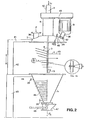
- Fig. 2 shows in partial left side view without outer wall and partial right side view a mixing device according to a second main embodiment, of which the lid has been removed and has been hoisted upwardly over at least the length of the mixing shaft, so that the mixing shaft, the mixing elements and the bottom scraper have become free from the mixing vessel and are visible.
- Fig. 2A shows on an enlarged scale in side view a detail of Fig. 2 of the pivotable connection of the knives to the mixing shaft.
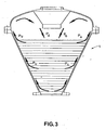
- Fig. 3 shows a diagram of the flow of the product in the intensive mixer according to the invention.
- the mixer is provided with a connical mixing vessel, that is generally indicated with 1, having a vertical axis 2, said vessel narrowing in a downward direction and in which at least one vertical mixing shaft 3 can rotate. From this mixing shaft 3 a number of knives 4 project gradually outwards, of which the outer end 5 extends until near the inner sidewall 6 of the vessel 1.
- the vessel 1 is closed at the upper side with a lid 7, of which the innerside is substantially elipsoide shape, on the one hand for the strength and on the other hand for the inward guiding of the product part Pu that possibly moves upwardly along the inner sidewall 6 into the lid 7 and in the direction of the centre of the lid, from which it again drops back as Pd downwardly in the mixing vessel 1.
- Fig. 3 shows this flow diagram.
- a drive motor 9 is fastened with the use of (not shown) seals and bearings on the central lid tube stub.
- the (not shown) outgoing driveshaft 10 is coupled with the mixing shaft 3.
- the mixing vessel 1 with the hoistable lid 7 can be closed vacuum tight by means of different types of quick fasteners, such as the screwbolt having a starhead 11 and the clamping screw 12, so that during the operation vacuum can be applied to the mixing vessel 1.
- quick fasteners such as the screwbolt having a starhead 11 and the clamping screw 12, so that during the operation vacuum can be applied to the mixing vessel 1.
- hoist means such as the arm 41, the double acting plunger 42, the cylinder 43 and the second arm 44 in Fig. 2.
- the mixing knives 4 can be cleaned, exchanged or repaired. It is also possible to inspect the vessel 1 internally or the lid 7 can be removed and quickly exchanged with an other lid with accessories.
- a scraper blade 13 is fastened in order to obviate a dead space in the bottom of the mixing vessel 1.
- An excentric tube stub 14 is also mounted on the lid 7, which stub can be opened and closed by means of an inspection lid 15. This is done with a pivotable arm 16, which can be screwed with a starhead 17 on a screwbolt 18 in the closing position in a uppertaining sidelog 19 of the stub 14.
- a flange 23 is fastened, on which the body is mounted of a ball segment valve 24, which contains a ball segment 25.
- the mixing vessel 1 is provided with an outer jacket 26 for heating and for cooling of the contents of a product P of the vessel 1.
- This jacket 26 carries the connecting tube stumps 28 and 29.
- the sidewall 6 is made of a so-called “template”, which is a double walled plate 13 that has been connected by welding in different places and is afterwards expended. Through the created hollow space again a cooling or heating medium can be circulated.
- the lid 7 comprises a tube stub 32 for a looking glass 33.
- the mixing shaft 3 carries a great number of knives 4 and has a high to very high number of revolutions N.
- the product to be treated experiences a very strong shearing at both the knives 4 as the inner sidewall 6, so that in a very short time a very intensive mixing of the product P is effected.
- a temperature rise can occur, which is counteracted by cooling the sidewall 6 of the mixing vessel 1.
- the number of revolutions N of the mixing vessel comprises 100 tot 1000 revolutions per minute.
- the knives 4 each carry at the outer end one or more mixing paddles 5, of which an outer edge extends parallel to and near the inner sidewall 6 of the vessel 1. Furthermore, the knives 4 are rod shaped and have a large radial dimension. Furthermore, the paddles 5 are plate shaped and have a small radial dimension. According to Fig. 1A at the left side of Fig. 1 the paddles 5 are limited pivotable over an angle (A) round the longitudinal axis of the rod shaped element.
- a second preferential embodiment of the invention is shown in the hoisted position of the lid 7 with accessories.
- the lid 7 is suspended on the upwardly and downwardly moveable horizontal arm 41 on the head of a hydraulic plunger 42 of a hoisting cylinder 43 which carries a fixed horizontal arm 44 at the upperside, on which the mixing vessel 1 is suspended. Also other that hydraulic hoisting tools can be applied.
- the knives 4 according to the invention comprise knives, of which the angle B with the vertical of at least a part of the knives is variable.
- FIG. 2A At a variant drawn at the right side of Fig. 2 the mixing shaft 3 and the knives 4 that are connected therewith are hollow and have outlet holes 45 for letting through and guiding of gasses and/or liquids U.
- Fig. 2A also a detail of the pivotable connection of the knives 4 with the mixing shaft 3 is shown. Here the scraper 13 at the lower end of the mixing shaft 3 is visible.
- the angle B is variable which the knives 4 make with the vertical.
- the outer sidewall 6 of the mixing vessel 1 is bound with a 1/2 tube spiral 46 for passing through a cooling and/or heating fluid.
- the lid 7 is provided with a tube stub 36 for the entrance of the product Pi.
- a flat outlet slide 47 with an operating lever 48 for the outgoing product PO is mounted.
- the mixing shaft 3 is accoupled by means of a transmission 49 with the inverted suspended drive motor 9, which transmission is fastened on the lid 7 by means of a heightened tube stub 8.
- a heightened tube stub 8 In the axis 2 an inlet 50 for liquid Li is mounted.
- the lid 7 is also provided with a port 38 for a low pressure sprayer 39 for process liquid and/or gas.
- the sidewall 6 of the mixing vessel 1 is provided at the right side with a port 34 for a thermometer 35.
Landscapes
- Chemical & Material Sciences (AREA)
- Chemical Kinetics & Catalysis (AREA)
- Mixers Of The Rotary Stirring Type (AREA)
- Crushing And Pulverization Processes (AREA)
- Accessories For Mixers (AREA)
Claims (15)
- Vorrichtung zum batchweisen Mischen, Kühlen, Erwärmen, Trocknen und/oder Granulieren von pulverartigen, körnigen und/oder pastösen Massen (P), welche einen konischen Mischbehälter (1) umfasst, der eine vertikale Achse (2) aufweist, wobei der Behälter sich nach unten hin verengt, und in welchem sich zumindest eine vertikale Mischwelle (3) drehen kann, wobei von der Mischwelle (3) mehrere Messer radial abragen, deren äusseres Ende sich bis in die Nähe der Seitenwand (6) des Behälters (1) erstreckt, dadurch gekennzeichnet, dass sie Messer (4) umfasst, welche an dem äusseren Ende ein oder mehrere Mischpaddel (5) tragen und die Mischwelle (3) mit einer Anzahl von Umdrehungen (N) dreht, welche zwischen 100 und 1.000 Umdrehungen pro Minute betragen, so dass die Zentrifugalkraft in Kombination mit der Drehung das Produkt (P) in einer Aufwärtsbewegung entlang der schrägen Seitenwand bewegt, nach welcher es entlang der vertikalen Achse (2) des Behälters (1) nach unten fällt, während dessen die zu behandelnde Masse sowohl an den Paddeln (5) als auch an der inneren Wand (6) eine Scherung erfährt, das eine und das andere derart, dass ein intensives Mischen des Produktes (P) bewirkt wird.
- Vorrichtung nach Anspruch 1, dadurch gekennzeichnet, dass die Messer (4) stangenartig ausgebildet sind und eine grosse radiale Abmessung aufweisen, wohin gegen die Paddel (5) plattenartig ausgebildet sind und eine geringe radiale Abmessung aufweisen und sie um die Längsachse des stangenförmigen Messers (4) um einen Winkel (A) drehbar begrenzt sind, wobei von diesen Paddeln sich eine radiale Aussenwand parallel zu und nahe zu der inneren Seitenwand (6) des Behälters (1) erstreckt.
- Vorrichtung nach einem oder mehreren der Ansprüche 1 und 2, dadurch gekennzeichnet, dass ein Schabmesser (13) an dem unteren Ende der Mischwelle (3) zum Vermeiden von totem Raum im Boden des Mischbehälters (1) angeordnet ist.
- Vorrichtung nach einem oder mehreren der Ansprüche 1 bis 3, bei welcher der Mischbehälter (1) mittels eines Deckels (7) auf der Oberseite geschlossen ist, dadurch gekennzeichnet, dass die Innenseite des Deckels (7) an dem Mischbehälter (1) im wesentlich ellipsenförmig ausgebildet ist, um den Teil des Produktes (Pu) zu führen, welcher sich entlang der inneren Seitenwand (6) von der Seitenwand (6) in die Richtung der Mitte des Deckels (7) nach oben bewegt, von wo aus es wieder nach unten in den Mischbehälter (1) als der Produktteil (Pd) fällt.
- Vorrichtung nach einem oder mehreren der Ansprüche 1 bis 4, dadurch gekennzeichnet, dass der Deckel (7) mit Hilfsmittel den Mischbehälter (1) luftdicht verschliessen kann, so dass Vakuum an dem Mischbehälter (1) angelegt werden kann.
- Vorrichtung nach einem oder mehreren der Ansprüche 1 bis 5, dadurch gekennzeichnet, dass der Deckel (7) mittels Schnellverschlüssen (11, 12) an dem Mischbehälter (1) befestigt ist, so dass der Deckel (7) mit Hilfsmittel nach dem Lösen der Schnellverschlüsse (11, 12) von dem Mischbehälter (1) abgehoben werden kann und nach der Bearbeitung und/oder Austausch erneut ausgetauscht und befestigt werden kann.
- Vorrichtung nach einem oder mehreren der Ansprüche 1 bis 6, dadurch gekennzeichnet, dass der Mischbehälter (1) mit einem äusseren Mantel (26) zum Erwärmen und/oder Kühlen der Inhalte des Produktes (P) des Behälters (1) versehen ist, wobei zu diesem Zweck die Rohranschlussstutzen (28, 29) vorhanden sind.
- Vorrichtung nach einem oder mehreren der Ansprüche 1 bis 7, dadurch gekennzeichnet, dass an dem unteren Ende des Mischbehälters (1) ein Kugelsegmentventil (24) angeordnet ist.
- Vorrichtung nach einem oder mehreren der Ansprüche 1 bis 8, dadurch gekennzeichnet, dass an dem unteren Ende des Mischbehälters (1) ein flacher Auslassschieber (47, 48) angeordnet ist.
- Vorrichtung nach einem oder mehreren der Ansprüche 1 bis 9, dadurch gekennzeichnet, dass die Mischwelle (3) mittels einer Übertragungsseinrichtung (49) mit einem umgedreht aufgehängten Antriebsmotor (9) verbunden ist, wobei an dem Deckel (7) ein aufragender Rohrstutzen (8) befestigt ist, welcher die Aufhängung (49) trägt, an welcher der Motor (9) umgedreht aufgehängt ist.
- Vorrichtung nach einem oder mehreren der Ansprüche 1 bis 10, dadurch gekennzeichnet, dass die Seitenwand (6) des Mischbehälters (1) mit einer Öffnung (34) für ein Thermometer (35) versehen ist.
- Vorrichtung nach einem oder mehreren der Ansprüche 1 bis 11, dadurch gekennzeichnet, dass der Deckel (7) mit einem Rohrstutzen (36) für den Einlass des Produktes (P) versehen ist.
- Vorrichtung nach einem oder mehreren der Ansprüche 1 bis 12, dadurch gekennzeichnet, dass der Deckel (7) mit einem Einlass (40) für einen Flüssigkeitszerstäuber (39) versehen ist.
- Vorrichtung nach einem oder mehreren der Ansprüche 1 bis 13, dadurch gekennzeichnet, dass der Deckel (7) an dem nach oben und nach unten bewegbaren, horizontalen Arm (41) an dem Kopf einer Kolbenstange (42) eines hydraulischen Hubzylinders (43) aufgehängt ist, welcher einen feststehenden horizontalen Arm (44) auf der oberen Seite trägt, an welchem der Mischbehälter (1) aufgehängt ist.
- Vorrichtung nach einem oder mehreren der Ansprüche 1 bis 14, dadurch gekennzeichnet, dass der Deckel (7) an dem nach oben und nach unten bewegbaren Arm (41) einer mechanisch Hubvorrichtung angeordnet ist.
Applications Claiming Priority (2)
| Application Number | Priority Date | Filing Date | Title |
|---|---|---|---|
| NL1006311A NL1006311C2 (nl) | 1997-06-13 | 1997-06-13 | Intensiefmenger. |
| NL1006311 | 1997-06-13 |
Publications (2)
| Publication Number | Publication Date |
|---|---|
| EP0885652A1 EP0885652A1 (de) | 1998-12-23 |
| EP0885652B1 true EP0885652B1 (de) | 2007-03-21 |
Family
ID=19765161
Family Applications (1)
| Application Number | Title | Priority Date | Filing Date |
|---|---|---|---|
| EP98201664A Expired - Lifetime EP0885652B1 (de) | 1997-06-13 | 1998-05-19 | Hochintensitätsmischer |
Country Status (4)
| Country | Link |
|---|---|
| EP (1) | EP0885652B1 (de) |
| JP (1) | JP4211015B2 (de) |
| DE (1) | DE69837365T2 (de) |
| NL (1) | NL1006311C2 (de) |
Cited By (1)
| Publication number | Priority date | Publication date | Assignee | Title |
|---|---|---|---|---|
| CN110813460A (zh) * | 2019-12-02 | 2020-02-21 | 苏州塔比诺机电有限公司 | 一种电子元件生产用原料研磨装置 |
Families Citing this family (10)
| Publication number | Priority date | Publication date | Assignee | Title |
|---|---|---|---|---|
| US6599005B2 (en) * | 1997-06-13 | 2003-07-29 | Hosokawa Micron Bv | Intensive mixer |
| JP2002181224A (ja) * | 2000-12-14 | 2002-06-26 | Mitsui Mining Co Ltd | 排出弁 |
| EP1791628A4 (de) * | 2004-09-21 | 2011-09-28 | Glaxo Group Ltd | Mischsystem und -verfahren |
| CN103041747A (zh) * | 2011-10-15 | 2013-04-17 | 四川制药制剂有限公司 | 便于观察反应情况的低功耗快速搅拌制粒机 |
| DE102013018094A1 (de) * | 2013-12-03 | 2015-06-03 | Merck Patent Gmbh | Mischvorrichtung und deren Verwendung |
| CN107282234A (zh) * | 2017-07-17 | 2017-10-24 | 邹铁梅 | 一种饲料生产用粉碎混合一体化设备 |
| CN108187840A (zh) * | 2017-12-28 | 2018-06-22 | 吴烨程 | 一种匀速间歇进料的多向粉碎过滤饲料装置 |
| CN115090211B (zh) * | 2022-06-08 | 2023-09-22 | 苏州思萃热控材料科技有限公司 | 一种铝碳化硅复合材料制备用烘干制粒一体设备 |
| CN116474607A (zh) * | 2023-04-15 | 2023-07-25 | 浙江恒翔新材料有限公司 | 非离子型毛纺专用高效净洗剂生产设备及生产方法 |
| DE102024128832A1 (de) * | 2024-10-07 | 2026-04-09 | Zeppelin Systems Gmbh | Mischer zum Verarbeiten von pulver- grieß- und /oder granulatförmigen Stoffen und Flüssigkeiten |
Family Cites Families (5)
| Publication number | Priority date | Publication date | Assignee | Title |
|---|---|---|---|---|
| IT1169505B (it) * | 1983-02-24 | 1987-06-03 | Luciano Occelli | Procedimento ed apparecchio per la mescolazione sotto vuoto di impasti per uso odontotecnico,orafo o simile |
| SE450545B (sv) * | 1984-10-19 | 1987-07-06 | Mit Ab | Forfarande och anordning vid framstellning av bencement for fixering av proteser |
| DE3768503D1 (de) * | 1987-09-10 | 1991-04-11 | Hosokawa Micron Europ | Vorrichtung zum trocknen von loesungsmittelhaltigem material. |
| US5265956A (en) * | 1991-09-30 | 1993-11-30 | Stryker Corporation | Bone cement mixing and loading apparatus |
| US5531519A (en) * | 1993-07-06 | 1996-07-02 | Earle; Michael L. | Automated bone cement mixing apparatus |
-
1997
- 1997-06-13 NL NL1006311A patent/NL1006311C2/nl not_active IP Right Cessation
-
1998
- 1998-05-19 DE DE69837365T patent/DE69837365T2/de not_active Expired - Lifetime
- 1998-05-19 EP EP98201664A patent/EP0885652B1/de not_active Expired - Lifetime
- 1998-06-01 JP JP15083898A patent/JP4211015B2/ja not_active Expired - Lifetime
Cited By (1)
| Publication number | Priority date | Publication date | Assignee | Title |
|---|---|---|---|---|
| CN110813460A (zh) * | 2019-12-02 | 2020-02-21 | 苏州塔比诺机电有限公司 | 一种电子元件生产用原料研磨装置 |
Also Published As
| Publication number | Publication date |
|---|---|
| NL1006311C2 (nl) | 1998-12-15 |
| EP0885652A1 (de) | 1998-12-23 |
| JP4211015B2 (ja) | 2009-01-21 |
| JPH1147573A (ja) | 1999-02-23 |
| DE69837365T2 (de) | 2007-12-13 |
| DE69837365D1 (de) | 2007-05-03 |
Similar Documents
| Publication | Publication Date | Title |
|---|---|---|
| US6599005B2 (en) | Intensive mixer | |
| EP0885652B1 (de) | Hochintensitätsmischer | |
| US4199266A (en) | Processing vessels | |
| ES2284609T3 (es) | Dispositivo para la manipulacion de sustancias. | |
| US4525072A (en) | Rotary mixing apparatus | |
| KR100787397B1 (ko) | 교반장치 | |
| JP2003117373A (ja) | 釜装置 | |
| JP2003126669A (ja) | 攪拌具とスクレーパとの配置構造及びそれを備えた釜装置 | |
| CN218130193U (zh) | 无菌级平板过滤洗涤干燥机 | |
| HU210406B (en) | Fluid processor apparatus | |
| KR100357739B1 (ko) | 배치믹서 | |
| US5513559A (en) | Food processing vat | |
| GB2116059A (en) | A rotary mixing apparatus | |
| JP2003144889A (ja) | ミキサ | |
| US4632025A (en) | Steam peeling apparatus | |
| CN219128957U (zh) | 一种硅酮胶生产用混合装置 | |
| JPH06296887A (ja) | アジテーターミル | |
| KR20170006173A (ko) | 유기성 폐기물 발효 감량 시스템 | |
| JP2003144896A (ja) | 排水装置及び釜装置 | |
| JP7712870B2 (ja) | 粒状物質または押出し物質の製造のための装置 | |
| CN118403582A (zh) | 一种化工反应釜 | |
| CN113975997A (zh) | 一种化妆品调配下料系统 | |
| JPH0357821B2 (de) | ||
| GB2194460A (en) | Agitator assembly for a rotary mixing apparatus | |
| CN218359257U (zh) | 一种混合反应釜 |
Legal Events
| Date | Code | Title | Description |
|---|---|---|---|
| PUAI | Public reference made under article 153(3) epc to a published international application that has entered the european phase |
Free format text: ORIGINAL CODE: 0009012 |
|
| 17P | Request for examination filed |
Effective date: 19981009 |
|
| AK | Designated contracting states |
Kind code of ref document: A1 Designated state(s): CH DE FR GB LI NL SE |
|
| AX | Request for extension of the european patent |
Free format text: AL;LT;LV;MK;RO;SI |
|
| AKX | Designation fees paid | ||
| RBV | Designated contracting states (corrected) |
Designated state(s): CH DE FR GB LI NL SE |
|
| 17Q | First examination report despatched |
Effective date: 20020508 |
|
| GRAP | Despatch of communication of intention to grant a patent |
Free format text: ORIGINAL CODE: EPIDOSNIGR1 |
|
| GRAS | Grant fee paid |
Free format text: ORIGINAL CODE: EPIDOSNIGR3 |
|
| GRAA | (expected) grant |
Free format text: ORIGINAL CODE: 0009210 |
|
| AK | Designated contracting states |
Kind code of ref document: B1 Designated state(s): CH DE FR GB LI NL SE |
|
| REG | Reference to a national code |
Ref country code: GB Ref legal event code: FG4D |
|
| REG | Reference to a national code |
Ref country code: CH Ref legal event code: EP |
|
| REF | Corresponds to: |
Ref document number: 69837365 Country of ref document: DE Date of ref document: 20070503 Kind code of ref document: P |
|
| REG | Reference to a national code |
Ref country code: SE Ref legal event code: TRGR |
|
| REG | Reference to a national code |
Ref country code: CH Ref legal event code: NV Representative=s name: SPIERENBURG & PARTNER AG, PATENT- UND MARKENANWAEL |
|
| ET | Fr: translation filed | ||
| PLBE | No opposition filed within time limit |
Free format text: ORIGINAL CODE: 0009261 |
|
| STAA | Information on the status of an ep patent application or granted ep patent |
Free format text: STATUS: NO OPPOSITION FILED WITHIN TIME LIMIT |
|
| 26N | No opposition filed |
Effective date: 20071227 |
|
| REG | Reference to a national code |
Ref country code: DE Ref legal event code: R082 Ref document number: 69837365 Country of ref document: DE Representative=s name: PATENTANWAELTE UND RECHTSANWALT WEISS, ARAT & , DE Ref country code: DE Ref legal event code: R082 Ref document number: 69837365 Country of ref document: DE Representative=s name: PATENTANWAELTE UND RECHTSANWALT DR. WEISS, ARA, DE |
|
| REG | Reference to a national code |
Ref country code: FR Ref legal event code: PLFP Year of fee payment: 19 |
|
| PGFP | Annual fee paid to national office [announced via postgrant information from national office to epo] |
Ref country code: NL Payment date: 20160504 Year of fee payment: 19 |
|
| PGFP | Annual fee paid to national office [announced via postgrant information from national office to epo] |
Ref country code: DE Payment date: 20160506 Year of fee payment: 19 Ref country code: GB Payment date: 20160506 Year of fee payment: 19 Ref country code: CH Payment date: 20160609 Year of fee payment: 19 |
|
| PGFP | Annual fee paid to national office [announced via postgrant information from national office to epo] |
Ref country code: SE Payment date: 20160506 Year of fee payment: 19 Ref country code: FR Payment date: 20160513 Year of fee payment: 19 |
|
| REG | Reference to a national code |
Ref country code: DE Ref legal event code: R119 Ref document number: 69837365 Country of ref document: DE |
|
| REG | Reference to a national code |
Ref country code: CH Ref legal event code: PL |
|
| REG | Reference to a national code |
Ref country code: SE Ref legal event code: EUG |
|
| REG | Reference to a national code |
Ref country code: NL Ref legal event code: MM Effective date: 20170601 |
|
| GBPC | Gb: european patent ceased through non-payment of renewal fee |
Effective date: 20170519 |
|
| PG25 | Lapsed in a contracting state [announced via postgrant information from national office to epo] |
Ref country code: SE Free format text: LAPSE BECAUSE OF NON-PAYMENT OF DUE FEES Effective date: 20170520 Ref country code: CH Free format text: LAPSE BECAUSE OF NON-PAYMENT OF DUE FEES Effective date: 20170531 Ref country code: LI Free format text: LAPSE BECAUSE OF NON-PAYMENT OF DUE FEES Effective date: 20170531 |
|
| REG | Reference to a national code |
Ref country code: FR Ref legal event code: ST Effective date: 20180131 |
|
| PG25 | Lapsed in a contracting state [announced via postgrant information from national office to epo] |
Ref country code: NL Free format text: LAPSE BECAUSE OF NON-PAYMENT OF DUE FEES Effective date: 20170601 |
|
| PG25 | Lapsed in a contracting state [announced via postgrant information from national office to epo] |
Ref country code: GB Free format text: LAPSE BECAUSE OF NON-PAYMENT OF DUE FEES Effective date: 20170519 Ref country code: DE Free format text: LAPSE BECAUSE OF NON-PAYMENT OF DUE FEES Effective date: 20171201 |
|
| PG25 | Lapsed in a contracting state [announced via postgrant information from national office to epo] |
Ref country code: FR Free format text: LAPSE BECAUSE OF NON-PAYMENT OF DUE FEES Effective date: 20170531 |