EP0316536B1 - Endgerät in einem Informationsübertragungssystem - Google Patents
Endgerät in einem Informationsübertragungssystem Download PDFInfo
- Publication number
- EP0316536B1 EP0316536B1 EP19880115164 EP88115164A EP0316536B1 EP 0316536 B1 EP0316536 B1 EP 0316536B1 EP 19880115164 EP19880115164 EP 19880115164 EP 88115164 A EP88115164 A EP 88115164A EP 0316536 B1 EP0316536 B1 EP 0316536B1
- Authority
- EP
- European Patent Office
- Prior art keywords
- polarity
- circuit
- transmission
- signal
- output
- Prior art date
- Legal status (The legal status is an assumption and is not a legal conclusion. Google has not performed a legal analysis and makes no representation as to the accuracy of the status listed.)
- Expired - Lifetime
Links
Images


Classifications
-
- H—ELECTRICITY
- H04—ELECTRIC COMMUNICATION TECHNIQUE
- H04L—TRANSMISSION OF DIGITAL INFORMATION, e.g. TELEGRAPHIC COMMUNICATION
- H04L12/00—Data switching networks
- H04L12/28—Data switching networks characterised by path configuration, e.g. LAN [Local Area Networks] or WAN [Wide Area Networks]
- H04L12/2803—Home automation networks
- H04L12/2838—Distribution of signals within a home automation network, e.g. involving splitting/multiplexing signals to/from different paths
-
- H—ELECTRICITY
- H04—ELECTRIC COMMUNICATION TECHNIQUE
- H04B—TRANSMISSION
- H04B3/00—Line transmission systems
- H04B3/54—Systems for transmission via power distribution lines
- H04B3/548—Systems for transmission via power distribution lines the power on the line being DC
-
- H—ELECTRICITY
- H04—ELECTRIC COMMUNICATION TECHNIQUE
- H04L—TRANSMISSION OF DIGITAL INFORMATION, e.g. TELEGRAPHIC COMMUNICATION
- H04L12/00—Data switching networks
- H04L12/28—Data switching networks characterised by path configuration, e.g. LAN [Local Area Networks] or WAN [Wide Area Networks]
- H04L12/2803—Home automation networks
-
- H—ELECTRICITY
- H04—ELECTRIC COMMUNICATION TECHNIQUE
- H04L—TRANSMISSION OF DIGITAL INFORMATION, e.g. TELEGRAPHIC COMMUNICATION
- H04L25/00—Baseband systems
- H04L25/38—Synchronous or start-stop systems, e.g. for Baudot code
- H04L25/40—Transmitting circuits; Receiving circuits
- H04L25/49—Transmitting circuits; Receiving circuits using code conversion at the transmitter; using predistortion; using insertion of idle bits for obtaining a desired frequency spectrum; using three or more amplitude levels ; Baseband coding techniques specific to data transmission systems
- H04L25/4917—Transmitting circuits; Receiving circuits using code conversion at the transmitter; using predistortion; using insertion of idle bits for obtaining a desired frequency spectrum; using three or more amplitude levels ; Baseband coding techniques specific to data transmission systems using multilevel codes
- H04L25/4923—Transmitting circuits; Receiving circuits using code conversion at the transmitter; using predistortion; using insertion of idle bits for obtaining a desired frequency spectrum; using three or more amplitude levels ; Baseband coding techniques specific to data transmission systems using multilevel codes using ternary codes
- H04L25/4925—Transmitting circuits; Receiving circuits using code conversion at the transmitter; using predistortion; using insertion of idle bits for obtaining a desired frequency spectrum; using three or more amplitude levels ; Baseband coding techniques specific to data transmission systems using multilevel codes using ternary codes using balanced bipolar ternary codes
-
- H—ELECTRICITY
- H04—ELECTRIC COMMUNICATION TECHNIQUE
- H04B—TRANSMISSION
- H04B2203/00—Indexing scheme relating to line transmission systems
- H04B2203/54—Aspects of powerline communications not already covered by H04B3/54 and its subgroups
- H04B2203/5404—Methods of transmitting or receiving signals via power distribution lines
- H04B2203/5408—Methods of transmitting or receiving signals via power distribution lines using protocols
-
- H—ELECTRICITY
- H04—ELECTRIC COMMUNICATION TECHNIQUE
- H04B—TRANSMISSION
- H04B2203/00—Indexing scheme relating to line transmission systems
- H04B2203/54—Aspects of powerline communications not already covered by H04B3/54 and its subgroups
- H04B2203/5404—Methods of transmitting or receiving signals via power distribution lines
- H04B2203/5416—Methods of transmitting or receiving signals via power distribution lines by adding signals to the wave form of the power source
-
- H—ELECTRICITY
- H04—ELECTRIC COMMUNICATION TECHNIQUE
- H04B—TRANSMISSION
- H04B2203/00—Indexing scheme relating to line transmission systems
- H04B2203/54—Aspects of powerline communications not already covered by H04B3/54 and its subgroups
- H04B2203/5429—Applications for powerline communications
- H04B2203/5458—Monitor sensor; Alarm systems
-
- H—ELECTRICITY
- H04—ELECTRIC COMMUNICATION TECHNIQUE
- H04B—TRANSMISSION
- H04B2203/00—Indexing scheme relating to line transmission systems
- H04B2203/54—Aspects of powerline communications not already covered by H04B3/54 and its subgroups
- H04B2203/5462—Systems for power line communications
- H04B2203/547—Systems for power line communications via DC power distribution
-
- H—ELECTRICITY
- H04—ELECTRIC COMMUNICATION TECHNIQUE
- H04B—TRANSMISSION
- H04B2203/00—Indexing scheme relating to line transmission systems
- H04B2203/54—Aspects of powerline communications not already covered by H04B3/54 and its subgroups
- H04B2203/5462—Systems for power line communications
- H04B2203/5483—Systems for power line communications using coupling circuits
-
- H—ELECTRICITY
- H04—ELECTRIC COMMUNICATION TECHNIQUE
- H04L—TRANSMISSION OF DIGITAL INFORMATION, e.g. TELEGRAPHIC COMMUNICATION
- H04L12/00—Data switching networks
- H04L12/28—Data switching networks characterised by path configuration, e.g. LAN [Local Area Networks] or WAN [Wide Area Networks]
- H04L12/2803—Home automation networks
- H04L2012/284—Home automation networks characterised by the type of medium used
- H04L2012/2843—Mains power line
-
- H—ELECTRICITY
- H04—ELECTRIC COMMUNICATION TECHNIQUE
- H04L—TRANSMISSION OF DIGITAL INFORMATION, e.g. TELEGRAPHIC COMMUNICATION
- H04L12/00—Data switching networks
- H04L12/28—Data switching networks characterised by path configuration, e.g. LAN [Local Area Networks] or WAN [Wide Area Networks]
- H04L12/2803—Home automation networks
- H04L2012/2847—Home automation networks characterised by the type of home appliance used
- H04L2012/285—Generic home appliances, e.g. refrigerators
Definitions
- the present invention relates to a terminal unit in an information transmission system including an information transmission line made up of signal lines of positive polarity and negative polarity and, more particularly, to a terminal unit of which plural units are connected to the transmission line and capable of transmitting and receiving transmission information to the transmission line and from the transmission line in the code of the alternate mark inversion (AMI) mode without being affected by the voltage polarity of the transmission line.
- AMI alternate mark inversion
- the information transmission technology is defined as technology relative to transmission of information that is to be or has been processed by an information processer such as a computer system, and the information transmission system for use in this field of technology in general includes a transmission line connecting the information proceser with one another and transmission equipment including input and output terminal units provided between the transmission lines and the information processer.
- the information transmission technology is not only applied to communications between places of business but recently has come to be used for household communication, such as "home bus system", or communications from outside to home.
- WO-A-8505234 discloses a high-speed digital transceiver for use in a PBX environment comprising twisted-pair wire cables interconnecting like transceivers, each transceiver being operative to exchange voice, data and control information in a packetized format over a common twisted-pair cable.
- each transceiver communicates packetized pulse code modulated information in a pure Alternate Mark inverted (AMI) coding, that is, without the introduction of bipolar violation pulses to provide timing.
- AMI Alternate Mark inverted
- Frame synchronization is acquired on the first pulse by the use of a digital circuit deriving synchronization from a local high-speed clock.
- a high-speed clock-driven digital circuit for synchronization acquisition eliminates the need for a phase-locked loop synchronization scheme and its concomitant finite acquisition delay.
- a receiving section employs a threshold selecting circuit which switches or makes thresholds in response to an expectation of the absence any bipolar violation in the transmitted signal.
- the effect of inter-symbol interference are further minimized by the provision of digital precompensation in the transmitted signal to maximize the slew rate between consecutive pulses.
- the precompensation scheme is based on a knowledge of the bit pattern and the amount of energy contained in a sequence of bits.
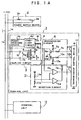
- FIG. 1A is a block diagram of a first example of a further prior art information transmission system as described, for example, in "Reports from Investigation and Research Commission on Household Intelligent System (Final Reports) - Section: Technical Standardization” (published in March 1986, by the Investigation and Research Commission on Household Intelligent System).
- FIG. 2 is an explanatory drawing of packet structure and character structure for information transmission
- FIG. 3 is an explanatory drawing of the relation between a signal transmitted over a transmission line and a signal delivered from a terminal unit.
- reference numeral 1 denotes a transmission line consisting of a positive line 1a and a negative line 1b for making power supply and signal transmission
- 2 denotes a power supply device consisting of a D.C. power source 2b and an inductance 2a serving as a high impedance to the transmitted signal for supplying power to various units connected to the transmission line
- 3 and 13 denote terminal units connected to the transmission line 1.
- the terminal unit 3 receives power from the transmission line 1 through a power receiving device 4 and makes transmission and reception of signals through a coupling circuit 5.
- the transmission circuit 8 and reception circuit 11 under the control of a transmission control device 12 exercising control for transmission and reception of signals in accordance with a protocol for the signal transmission, perform transmission to and reception from the transmission line 1 of signals through the coupling circuit 5.
- the power receiving device 4 is made up of an inductance 4b connected with the positive line 1a of the transmission line 1 for serving as a high impedance to the transmission signal and a stabilizer circuit 4a for voltage stabilization and takes in power from transmission line 1.
- the coupling circuit 5 consists of capacitors 7a and 7b, whose ends on one side are connected with both terminals of a winding 6a of a transformer 6, including winding 6a, 6b, and 6c, and the ends on the other side are connected with the positive line 1a and negative line 1b of the transmission line 1, respectively.
- the windings 6b and 6c are connected in series and the middle point thereof is connected with the positive terminal of the power receiving device 4.
- the transmission circuit 8 includes transistors 9a and 10a, with the collectors of the transistors 9a and 10a connected with one ends of the winding 6b and 6c of the transformer 6, respectively, with the emitters connected with ground of the power receiving device 4, and with the bases connected with output terminals 12a and 12b of the transmission control device 12 through resistors 9c and 10c, respectively.
- bases of the transistors 9a and 10a are connected with the power source positive line of the power receiving device 4 through resistors 9b and 10b, respectively.
- the reception circuit 11 includes two comparators 11c and 11d, and one input terminals of the comparators 11c and 11d are supplied with a reference voltage obtained from divided voltage by resistors 11a and 11b, while the other input terminals are connected with the windings 6b and 6c of the coupling circuit 5, respectively.
- Output terminals of the comparators 11c and 11d are joined together and connected with the power source positive line of the power receiving device 4 through a resistor 11e and also connected with an input terminal 12c of the transmission control device 12.
- the input terminals of the power receiving device 4 and the capacitors 7a and 7b as input terminals to the coupling circuit 5 are connected with each other and connected with the positive line 1a and negative line 1b of the transmission line 1, respectively.
- the transmission control device 12 in order to transmit the signal of packet structure and character structure as shown in FIGs. 2(a) and 2(b) in the AMI code, delivers its outputs to the output terminals 12a and 12b, alternately switched therebetween each time the code "0" is transmitted.
- the signal as shown in FIG. 2(a) is structured of priority code PR, self address SA, destination address DA, control code CW, message length BC, data DATA, and check code FCC. Since such a signal is transmitted in an asynchronous manner, the ST bit, or start bit, as shown in Fig. 2(b), is made to be "0" for each terminal unit and the polarity of the transmission line 1 is made to be of the same polarity as that of the supply voltage.
- the terminal unit 13 is of the same structure as that of the terminal unit 3.
- the transmission control device 12 After confirming that the transmission line 1 is in an idle state according to a signal from the reception circuit 11, delivers, according to the packet structure as shown in Fig. 2(a), the polarity making the positive line 1a positive.
- the voltage that is generated in the winding 6b at the time of transmission of the code "0" of the start bit is subjected to level comparison in the comparator 11c, and a voltage as the result of the comparison is applied to the input terminal 12c, whereby the fact that the delivered code is correctly transmitted is verified.
- the code "1" is then transmitted, it is achieved by bringing both of the output terminals 12a and 12b to a low level, thereby causing both the transistors 9a and 10a turned OFF. That is, since nothing is output to the transmission line 1, it goes to the voltage level of the power supply unit 2.
- the output terminal 12a is brought to a high level, whereby the transistor 9a is turned ON and a voltage with the reverse polarity to that of the start bit is generated to that a voltage with the reverse polarity to that of the supply voltage is applied to the transmission line 1.
- serial transmission of an AMI coded baseband signal can be performed.
- reception of a signal is performed such that the signal transmitted, for example, only by the terminal unit 13 is received by means of the winding 6a through the capacitors 7a and 7b, the level is compared by the comparators 11c, 11d the same as in the case of transmission, and the voltage as the result of the comparison is applied to the input terminal 12c, whereby the transmission control device 12 receives the signal.
- Fig. 3(a) and Fig. 3(b) show signals which the terminal units 3 and 13 desire to transmit, respectively, and Fig. 3(c) shows the signal actually impressed on the transmission line 1.
- the code "0" of the start bit transmitted at first is output from each of the terminal units 3 and 13, with the same polarity, and therefore, the output voltage is correctly superposed on the supply voltage in the same polarity so as to be transmitted as the code "0".
- both the terminal units 3 and 13 also operate equally so as not to superpose any signal on the transmission line 1.
- both the terminal units 3 and 13 output a signal of the reverse polarity to that of the start bit, and therefore, the transmitted signal and received signal agree with each other and the transmission is carried out correctly.
- the terminal unit 3 tries to transmit the code "0" while the terminal unit 13 tries to transmit the code "1", and as a result, the transmission line 1 comes into a state transmitting the code "0", whereupon since the transmitted signal and received signal are not in agreement for the terminal unit 13, it stops its transmission, while only the terminal unit 3 continues its transmission.
- CSMA/CD carrier sense multiple access/collision detection
- the terminal units 3 and 13 In order that the CSMA/CD transmission control is performed for certain, the terminal units 3 and 13 must deliver the code "0" of the start bit in the same polarity to the transmission line 1.
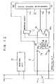
- Fig. 1B is a circuit diagram showing an example of a prior art information transmission apparatus as described, for example, in "Reports from Investigation and Research Commission on Household Intelligent System (Final Reports) - Section: Technical Standardization” (published in March, 1986, by the Investigation and Research Commission on Household Intelligent System.)
- reference numeral 1 denotes an information transmission line (hereinafter to be called the transmission line), and the transmission line 1 consists of a signal line 1a to which the transmitted signal has positive polarity relation and a signal line 1b to which it has negative polarity relation.
- Reference numerals 3 and 13 denote terminal units connected with each other through the transmission line 1 and transmitting information in an AMI coded baseband signal.
- the terminal units 3, 13 each include a coupling circuit 5 coupling itself with the transmission line 1, transmission circuit 8, reception circuit 11, and a transmission control device 12.
- the coupling circuit 5 consists of terminals 51, 52 serving as input terminals, capacitors 7a, 7b connected in series with the terminals 51, 52, respectively, and a coupling transformer having windings 6a, 6b, and 6c.
- the transmission circuit 8 consists of transistors 9a, 10a, of which collectors are connected with the windings 6b, 6c of the coupling transformer and emitters are grounded, and base resistors 9c, 10c. The other ends of the resistors 9c, 10c are connected with the transmission control device 12.
- the AMI code is transmitted by turning the transistors 9a, 10a ON and OFF each time the code "0" is transmitted.
- the reception circuit 11 consists of comparators 11c, 11d of which one input terminals are connected with the windings 6b, 6c of the coupling transformer 6 and the other input terminals are connected with a reference voltage generating terminal constituted of a series circuit of resistors 11a, 11b, and an OR circuit having the outputs of the comparators 11c, 11d as its input terminals.
- the output terminal of the OR circuit 11f is connected with the transmission control device 12.
- the reception circuit 11 is a circuit to convert an AMI code into an NRZ code.
- the transmission control device 12 is constituted of a microcomputer and the like and includes a start bit transmission terminal 12b for transmitting a signal in positive polarity relation to the signal line 1a, and a transmission terminal 12a for transmitting a signal in negative polarity relation thereto, both the terminals delivering their outputs alternately each time the code "0" is transmitted in order to transmit an AMI code through the transmission circuit 8 to the transmission line 1, and it also includes a reception terminal 12c connected with the output of the reception circuit 11 for receiving a signal transmitted over the transmission line 1.
- the information transmission apparatus of the above described organization while assembling and disassembling the transmission packet as shown in Fig. 2, detects collision by comparing the transmitted data from the transmission terminals 12a, 12b with the data transmitted over the transmission line 1 as shown in Fig. 3, and when it loses in the competition of the collision, it stops its transmission.
- the transmission control circuit 12 Upon receipt of a request for transmission, the transmission control circuit 12 confirms that the transmission line 1 is in an idle state from a signal from the reception terminal 12c, and then, performs data transmission in the AMI code according to the packet structure as shown in Fig. 2(a) from the start bit (SB) for character synchronization.
- PR denotes priority code
- SA denotes self address
- DA denotes destination address
- CW denotes control code
- BC denotes message length
- DATA denotes data
- FCC denotes check code.
- the transmission control circuit 12 keeps its transmission terminal 12b at a high level during a one bit period corresponding to the start bit, whereby the transistor 10a is turned ON and the source voltage is applied to the winding 6c.
- a voltage corresponding to the source voltage is induced in the winding 6a and applied through the capacitors 7a, 7b to the transmission line 1 with the polarity as shown in the figure, that is, with positive polarity to the signal line 1a.
- the transmission terminal 12a In transmitting the code "0" in the next place, the transmission terminal 12a is brought to a high level, whereby the transistor 9a is turned ON, reverse voltages to the above are generated in the windings of the coupling transformer 6, and as a result, a signal is transmitted to the transmission line 1 with the polarity in positive relation to the signal line 1b.
- both the transmission terminals 12a and 12b are brought to a low level.
- the codes "0" and “1" transmitted by turning the transistors 9a and 9b ON/OFF are subjected to level comparison in the comparators 11c, 11d at all times, converted into NRZ signals by the OR circuit 11f, and the transmitted data and the received data of the transmitted data over the transmission line 1 obtained through the reception circuit 11 are compared and detection of collision is performed as shown in Fig. 3.
- the next code is equally “1" for both the terminal units 3 and 13 and it is transmitted as the code "1" over the transmission line 1. Then, when the terminal unit 3 delivers the code "0" and the terminal unit 13 delivers the code "1", the code "0" is transmitted over the transmission line 1. Therefore, the terminal unit 13 detects a collision from the difference between the delivered data and the received data from the transmission line 1, and hence, it thereafter performs only signal reception.
- Fig. 1C is a circuit diagram of a prior art information transmission apparatus as described, for example, in "Reports from Investigation and Research Commission on Household Intelligent System (Final Reports) - Section: Technical Standardization” published in March, 1986, by the Investigation and Research Commission on Household Intelligent System.
- Fig. 2 is a drawing showing packet structure and character structure for information transmission
- Fig. 3 is a time chart indicating the relationship between a signal transmitted over a transmission line and signals delivered from terminal units.
- reference numeral 1 denotes a transmission line for signal transmission consisting of a positive signal line 1a of the positive polarity and a negative signal line 1b of the negative polarity.
- Reference numerals 3, 13 denote terminal units connected to the transmission line 1 and of the following construction.
- Reference numeral 12 denotes a transmission control device for transmission and reception of information in accordance with a predetermined protocol, and the same is provided with a transmission data positive output terminal 12a and a transmission data negative output terminal 12b for transmitting signals of the packet structure and character structure as shown in Figs. 2(a), 2(b) in alternate mark inversion code (AMI code) having redundancy in the direction of the amplitude and alternately delivers its outputs at these output terminals 12a, 12b each time the code "0" is output.
- Reference numerals 9a, 10a denote transistors, with their respective base terminals connected with the transmission data positive output transistor 12a and the transmission data negative output terminal 12b and form a common-emitter amplifier.
- Reference numeral 6 denots a coupling transformer, with windings 6b, 6c connected with the collector terminals of the transistors 9a, 10a, and the center tap of the windings 6a, 6b supplied with the source voltage. Therefore, according to turning ON/OFF of the transistors 9a, 10a, collector-emitter current flows and thereby an AMI coded signal (hereinafter to be called the AMI signal) appears across the winding 6a.
- Reference numerals 7a, 7b denote capacitors for delivering the AMI signal appeared across the winding 6a of the transformer 6 to the transmission line 1 therethrough.
- Reference numeral 11 denotes a reception circuit made up of an AMI decoder circuit or the like and is connected with the side of the windings 6b, 6c of the transformer 6.
- the AMI signal over the transmission line 1 is input by way of the capacitors 7a, 7b and the transformer 6 to the reception circuit 11 made up of an AMI decoder circuit or the like, and the result of the decoding is input to the received signal input terminal 12c of the transmission control device 12.
- the transmission control device 12 After confirming that the transmission line 1 is in an idle state according to a signal from the reception circuit 11 made up of an AMI decoder circuit or the like, delivers, according to the packet structure as shown in Fig. 2(a), the start bit "0" of each character with the polarity making the positive signal line 1a positive.
- the voltage generated in the transformer 6 at the time the code "0" of the start bit is transmitted is also input to the reception circuit 11 made up of an AMI decoder circuit or the like and the result of decoding is read into the received signal input terminal 12c, whereby the fact that the delivered code is correctly transmitted is verified.
- the code "1" is then transmitted, it is achieved by bringing both of the output terminals 12a and 12b to a low level, thereby causing both the transistors 9a and 10a turned OFF. That is, since nothing is output to the transmission line 1, it exhibits zero voltage.
- the output terminal 12b is brought to a high level, whereby the transistor 10a is turned ON and a voltage with the reverse polarity to that for the start bit is generated, so that a corresponding signal is output to the transmission line 1.
- serial transmission of an AMI coded baseband signal is carried out.
- reception of a signal is performed such that the signal transmitted, for example, only by the terminal unit 13 is received by the transformer 6 through the capacitors 7a, 7b, the signal is decoded in the reception circuit 11 made up of an AMI decoder circuit or the like the same as in the case of transmission, and the decoded signal is input to the received signal input terminal 12c, whereby the transmission control device 12 receives the signal.
- Fig. 3(a) and Fig. 3(b) show signals which the terminal units 3 and 13 attempt to transmit and Fig. 3(c) shows the signal actually impressed on the transmission line 1.
- the code "0" of the start bit to be transmitted at first is output with the same polarity by each of the terminal units 3 and 13, and therefore, the same is correctly transmitted over the transmission line 1 as the code "0".
- both the terminal units 3 and 13 also operate equally so as not to deliver any signal to the transmission line 1.
- both the terminal units output a signal of the reverse polarity to that of the start bit, and, when both the terminal units deliver the same code, the transmitted signal and received signal agree with each other, and therefore the transmission is carried out correctly.
- the terminal unit 3 tries to transmit the code "0" while the terminal unit 13 tries to transmit the code "1".
- the transmission line 1 comes to be transmitting the code "0", whereupon since the transmitted signal and received signal are detected to be in disagreement by the terminal unit 13, it stops its transmission, while the terminal unit 3 continues its transmission since the transmitted signal and received signal are in agreement.
- a transmission control system such that, when a collision occurs between a terminal unit 3 and another terminal unit 13, one of them remains undefeated, or "CSMA/CD system with one unit remaining undefeated", can be attained.
- the terminal units 3 and 13 In order that the "CSMA/CD system with one unit remaining undefeated" is performed for certain, the terminal units 3 and 13 must deliver the start bit code "0" in the same polarity relation to the transmission line 1. If there is a unit connected in reverse polarity relation, the signal level of the transmission line 1 becomes unstable when the start level is transmitted, whereby it occurs that neither of the collided terminal units can confirm agreement between the transmitted and received signals and the condition of the "one unit remaining undefeated" becomes unachievable.
- a terminal unit for use in an information transmission system disposed between an information transmission line in the information transmission system constituted of signal lines for transmitting a signal by conduction therethrough of a direct current having positive polarity and negative polarity and a controlled equipment as one terminal of the system and including at least a coupling circuit for transmitting and receiving a signal to and from the transmission line by converting the signal into a dirct current as aforesaid and converting such a direct current into the signal, a transmission control circuit controlling transmission and reception of a signal according to a protocol for signal transmission, and a transmission circuit and a reception circuit disposed between said coupling circuit and transmission control circuit for mailing signal transmission and reception, respectively, characterized by a polarity detection circuit for detecting the polarity of the direct current voltage supplied to each of said signal lines, and a polarity switching circuit for switching polarities of the signal delivered to said transmission line depending upon the result of detection in said polarity detection circuit.
- An information transmission system comprises a transmission line for supplying D.C. power to terminal units connected thereto and also for transmitting thereover a signal from a terminal unit, a polarity identification means for identifying the polarity of a D.C. voltage supplied to the transmission line, and a switching means for switching the polarities of a signal to be transmitted to the transmission line depending upon the output of the polarity identification means.
- An information transmission apparatus includes a plurality of terminal units connected to an information transmission line, each of the terminal units serially transmitting an encoded baseband signal with a predetermined polarity and in a start-stop synchronization system, and provides each of the terminal units with a polarity detection circuit for detecting the polarity of a start bit which is received at first after the power source is turned on and a switching circuit for switching the polarities of the encoded baseband signal depending upon the output of the polarity detection circuit.
- An information transmission apparatus is adapted such that a signal indicating a polarity is output from its polarity setting device to the transmission line for information transmission, an encoded baseband signal is serially transmitted from its terminal unit connected to the transmission line with the polarity in predetermined relation to the polarity that is indicated by the polarity fretting device, the polarity of the transmission line is detected by a polarity detection circuit according to the signal output from the polarity setting circuit, and the polarities of the baseband signal is switched by a polarity switching circuit depending upon the output of the polarity detection circuit.
- Fig. 4 is a block diagram of an information transmission apparatus according to a first embodiment of the present invention.
- a power receiving device 4 includes an inductance 4b disposed on its input side for serving as a high impedance to the transmitted signal and a full-wave rectifier circuit 4c connected in series therewith having a stabilizer circuit 4a connected to its output.
- a resistor 14 connected at its one end with one input terminal of the full-wave rectifier circuit 4c and at its other end with the anode of a light emitting diode of a photocoupler 15.
- the cathode of the photocoupler 15 is connected with the other input terminal of the full-wave rectifier circuit 4c.
- the emitter of the photocoupler 15 and the emitter of a transistor 18 together are connected with the ground of the power receiving device 4 and the collector thereof is connected through a resistor 16 with the positive line of the power receiving device 4 and also connected through a resistor 17 with the base of the transistor 18.
- the collector of the transistor 18 is connected through a relay 19 with the positive line of the power receiving device 4.
- Contacts 20 and 21 of the relay 19 are connected, respectively, between output terminals 12a, 12b of a transmission control device 12 and resistors 9c, 10c connected in series with the bases of transistors 9a, 10a.
- a normally open contact 20a is connected with a normally closed contact 21b and a normally closed contact 20b is connected with a normally open contact 21a.
- the normally open contact 20a and normally closed contact 21b are connected with the output terminal 12a of the transmission control device 12
- the normally closed contact 20b and normally open contact 21a are connected with the output terminal 12b of the transmission control device 12.
- a supply voltage from the power supply unit 2 is full-wave rectified in the full-wave rectifier circuit 4c and converted to a predetermined voltage value by the stabilizer circuit 4a to be supplied to every circuit of the terminal unit 3.
- the supply voltage from the transmission line 1 is applied through the resistor 14 to the light emitting diode of the photocoupler 15 in the forward direction whereby the phototransistor is turned ON. Hence, no base current flows in the transistor 18, and thereby, the transistor 18 remains OFF and the relay 19 is held in an unoperating state. Therefore, relative to the contact 20, the normally closed contact 20b is in connection with the common contact 20c, and relative to the contact 21, the normally closed contact 21b is in connection with the common contact 21C.
- the output terminal 12a of the transmission control device 12 is connected through the contact 20 and resistor 9c with the base of the transistor 9a, while the output terminal 12b is connected through the contact 21 and resistor 10c with the base of the transistor 10a.
- the output from the output terminal 12a of the transmission control device 12 can deliver a signal of the polarity reverse to that of the supply voltage to the transmission line 1.
- the output from the output terminal 12a of the transmission control device 12 can deliver a signal of the polarity reverse to that of the supply voltage to the transmission line 1.
- the output terminal 12b of the transmission control device 12 is connected through the contact 20 and resistor 9c to the base of the transistor 9a, while the output terminal 12a is connected through the contact 21 and resistor 10c to the base of the transistor 10a.
- the signal generated in the winding 6a of the transformer 6 caused by the output from the output terminal 12b of the transmission control device 12, which is for outputting the signal of the same polarity as that of the supply voltage becomes that of the polarity reverse to the arrow X in Fig. 4.
- the signal of the same polarity as the supply voltage can be delivered to the transmission line 1 and the delivered signal becomes that of the same polarity as the code "0" of the start bit of each character.
- the output terminal 12a of the transmission control device 12 is enabled to deliver to the transmission line 1 the signal of the reverse polarity to that of the supply voltage.
- the contacts 20, 21 may be disposed between the winding 6a of the transformer 6 and the capacitors 7a, 7b, between the capacitors 7a, 7b and the input terminal of the terminal unit 3, or between the collectors of the transistors 9a, 10a and the transformer 6.
- the arrangement adapted such that the polarities of the transmission signal are switched by contacts of the relay 19 it is also possible to arrange an apparatus such that, as shown in the block diagram of a second embodiment of Fig. 5, the output of the phototransistor of the photocoupler 15 is output to a control terminal 12d provided on the transmission control device 12, whereby the polarity of each of the outputs of the output terminal 12a and the output terminal 12b is determined.
- the transmission control device 12 is provided with a program as shown in the flow chart of Fig.
- the power receiving device 4 including the full-wave rectifier 4c was arranged so as to use the voltage supplied to the transmission line 1 for supplying power to the terminal unit 3, but the power operating the terminal unit 3 can be supplied from other system using such as the commercial power source without impairing the applicability of the present invention.
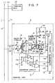
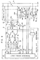
- FIG. 7 wherein like reference numeral to those in the above described Fig. 1B denote corresponding parts, 11 denotes a reception circuit and output terminals of comparators 11d, 11c as the constituents of the reception circuit 11 are connected with polarity identification terminals 12d, 12e of the transmission control device 12. That is, when the signal line 1a of the transnission line 1 is of the positive polarity, the terminal 12d goes to a high level, and when it is of the reverse polarity, the terminal 12e goes to a high level.
- Reference numeral 40 denotes a polarity switching circuit, and this polarity switching circuit 40 is made up of a transistor 43 whose base terminal is connected through a resistor 44 with a switching terminal 12f provided on the transmission control device 12 and emitter is grounded, a relay 45 connected with the collector of the transistor 43, and two poles of contacts 41, 42 of the relay 45.
- the normally open contact 41a of the contact 41 and the normally closed contact 42b of the contact 42 are joined together and connected with the transmission terminal 12a. And, the normally closed contact 41b of the contact 41 and the normally open contact 42a of the contact 42 are joined together and connected with the transmission terminal 12b.
- the common contact 41c, 42c of the contacts 41, 42 are, respectively, connected through resistors 9c, 10c with bases of transistors 9a, 10a of the transmission circuit 8.
- the switching terminal 12f after power-on resetting, outputs a high level when the polarity identification terminal 12e has gone to a high level earlier than the identification terminal 12d, and outputs a low level when reversely the identification terminal 12d has gone to a high level earlier.
- the transmission control device 12 is constituted of a microcomputer and the like and the identification of the polarity and outputting signals to the switching terminal 12f and transmission terminals 12a, 12b are achieved by software.
- the transmission terminal 12b is that for transmitting the start bit, which goes to a high level during the one-bit period when the code "0" as the start bit is transmitted. And, when the code "0" is transmitted in the next place, the transmission terminal 12a goes to a high level, and thereafter, each time the code "0" is transmitted, they alternately go to a high level, whereby an AMI signal is transmitted over the transmission line 1.
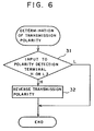
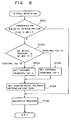
- Fig. 8 is a flow chart showing the relative operation. Description of the operation will be given below with reference to the flow chart.
- a signal of the packet structure and character structure as shown in Fig. 2 is transmitted from another terminal unit 13 to the transmission line 1. That is, the code "0" as the start bit (SB) transmitted in positive polarity relation to the signal line 1a is applied through the capacitors 7a, 7b to the winding 6a.
- the signal for the start bit (SB) is turned to an induced voltage in the winding 6b and compared in thc comparator 11c with a reference voltage obtained by means of resistors 11a, 11b for identification of its level.
- the received voltage is higher than that, it is taken as a transmission of a code "0" and a high level is output to the polarity identification terminal 12d for identification of the code "0" of the transmission polarity, and also, it is applied as a received signal to the signal reception terminal 12c through the OR circuit 11f.
- the transmission control device 12 in a stand-by state for signal reception, is monitoring the polarity identification terminals 12d, 12c at all times.
- the transmission control device 12 starts a reception process and sees a transmission polarity determination flag (step ST-21).
- step ST-22 If the flag is "0", that is, if the transmission polarity is not yet determined, then it is identified on which terminal of the polarity identification terminals 12d, 12e a start bit (SB) is impressed (step ST-22).
- step ST-23 the control terminal 12f is set to a high level (step ST-23), whereby the transistor 43 is turned ON and the relay 9 is operated.
- the normally open contacts 41a, 42a are closed and the transmission terminal 12a is connected to the base of the transistor 9a and the transmission terminal 12b is connected to the base of the transistor 10a, respectively.
- the transmission polarity determination flag is set (step ST-25) and data are received from the reception terminal (step ST-26).
- the transmission control device 12 After confirming that the transmission line 1 is idle the same as in the case of the prior art, transmits the code "0" as the start bit of the PR (priority code) as shown in the above Fig. 2. That is, the start bit transmission terminal 12b is held at a high level for a one-bit period and the transistor 10a is turned ON, whereby the start bit is transmitted in such polarity that the signal line 1a of the transmission line 1 is provided with positive polarity. Thereafter, the transmission terminals 12a, 12b are alternately brought to a high level each time the code "0" is transmitted according to the AMI code, and thereby a signal is transmitted in the AMI code.
- the input terminals 51, 52 of the terminal unit 3 are connected in the reverse polarity to that shown in the figure, namely, the input terminal 51 is connected to the signal line 1b and the input terminal 52 is connected to the signal line 1a, and the power supply is turned on, and if then the signal from the terminal unit 13 the same as that in the above described embodiment is transmitted, the start bit (SB) is given in positive polarity relation to the signal line 1a.
- the winding 6a is impressed thereon with a voltage of the positive polarity relative to the capacitor 7b and the voltage induced in the winding 6c is subjected to level comparison in the comparator 11d, whereby the polarity identification terminal 12e is brought to a high level.
- the control terminal 12f is set to a low level (step ST-24), whereby the relay 45 is turned OFF. That is, the start bit transmission terminal 12b is connected through the normally closed contact 41b and resistor 9c to the base of the transistor 9a.
- the start bit transmission terminal 12b is brought to a high level, the transistor 9a is turned ON, and the code "0" of the start bit providing the capacitor 7b with positive polarity is transmitted to the winding 6a of the coupling transformer 6.
- the input terminal 52 is connected with the signal line 1a, it is made possible to transmit the start bit so that the signal oine 1a is provided with positive polarity.
- the switching of the transmission polarities for the start bit is adapted to be performed by the relay contacts as the switching element inserted between the transmission terminals 12a, 12b and the transmission circuit 8, the switching element may be inserted between the transmission circuit 8 and the coupling circuit 5 or between the input terminals 51, 52 and the transmission line 1.
- the switching of the polarities may be carried out by software provided in the transmission control device 12 adapted such that, in the process after the identification of the polarity of the start bit (SB) as shown in Fig. 8 (step ST-22), the transmission terminal 12b is provided with the function of the start bit transmission terminal instead of the setting of the control terminal 12f to a high level (step ST-23), and the transmission terminal 12a is provided with the function of the start bit transmission terminal instead of the setting of the control terminal 12f to a low level (step ST-23).
- terminal units When power are turned on simultaneously for all the terminal units, some terminal units become unable to make transmission, and therefore, it may be arranged such that certain terminal units will transmit a signal indicating the start bit for polarity identification when a predetermined period has elapsed after the turning on of the power.
- the polarity identification signal may be transmitted, for example, with one character of the packet as shown in Fig. 2(a) set to the codes "0" or with the start bit (SB) and the 0-th bit (b0) of the character as shown in Fig. 2(b) set to the codes "0". It will work well only by setting the period longer than the maximum length of the packet.
- a baseband signal was transmitted coded in the AMI mode but other way of coding such as the NRZ mode may also be used.
- reference numeral 120 denotes a polarity detection signal output terminal newly provided on the transmission control device 12, from which the signal is output when the transmission control device 12 read the polarity of the transmission line 1.
- Reference numeral 63 denotes a transistor, base terminal thereof being connected with the polarity detection output terminal 120, for driving a relay 64 connected with its collector terminal.
- Reference numerals 64a, 64b are contacts of the relay 64, of which the contact 64a is a make contact and the contact 64b is a break contact.
- Reference numeral 65 denotes a polarity setting device and a case where a polarity is indicated by a D.C. current is illustrated.
- Reference numeral 65a denotes a power source for supplying the transmission line 1 with a D.C. current
- 65b denotes a current limiting resistor connected with the power source 65a
- 65c denotes a switch for switching on and off the D.C. current indicating the polarity
- 65d denotes a current detector connected across the current limiting resistor 65b for detecting the current quantity.
- Reference numeral 66 denotes a current limiting resistor, whereby too large an amount of D.C. current indicating the polarity is prevented from flowing into the terminal unit 3, and it is connected with light emitting diodes constituting photocouplers 67, 68.
- the photocouplers 67, 68 provide a polarity detection circuit of the transmission line 1, whose output terminals 67a, 68a are connected through pull-up resistors 69, 61 with the power source and also connected with polarity detection input terminals 121, 122 of the transmission control device 12.
- Reference numeral 123 denotes an output terminal of a polarity setting signal for switching the transmission polarities of the baseband signal depending upon signals input to the polarity detection input terminals 121, 122 and it is connected with a control input terminal 70a of a polarity switching circuit 70.
- Reference numeral 70b, 70c denote output terminals of the polarity switching circuit 70 and these are connected with the base terminals of transistors 9a, 10a, respectively.
- the output terminals 70b, 70c deliver outputs of a transmission data positive output terminal 12a and a transmission data negative output terminal 12b selected by the control input terminal 70a.
- the transmission control device 12 is initialized upon turning on of the power source and then a polarity setting sequence of the transmission line as shown in Fig. 10 is executed.
- the transmission control device 12 outputs a high level signal from the polarity detection signal output terminal 120 and supplies a base current to the transistor 63.
- the transistor 63 is thereby turned ON and the relay 64 is operated (step ST-1).
- the contact 64a is closed, while the contact 64b is opened, and a loop passing through the positive line 1a of the transmission line 1 ⁇ contact 64a ⁇ LEDs of the photocouplers 67, 68 ⁇ current limiting resistor 66 ⁇ negative line 1b is thereby formed. Since, in the present situation, no current is supplied from the polarity setting device 65, outputs of the photocouplers are both at a high level, and the transmission control device 12, reading the input levels at the polarity detection input terminal 121, 122, detects the fact of there being no current supply (step ST-2). If then the switch 65c of the polarity setting device 65 for indicating the polarity is closed, a current is supplied through the transmission line 1 to the terminal unit 3.
- the transmission control device 12 detects the start of the current supply by reading the levels of the polarity detection input terminals 121, 122, and further reads the polarity detection input terminals 121, 122 several times, and thereby reads the polarity of the transmission line 1 indicated by the polarity setting device 65 (step ST-3).
- the transmission control device 12 according to the read value, brings the output of the polarity setting signal output terminal 123 to a high level and supplies it to the control input terminal 70a of the polarity switching circuit 70.
- the polarity switching circuit 70 operates such that the signal of the output terminal 12a is delivered to the output terminal 70c and the signal of the output terminal 12b is delivered to the output terminal 70b. That is, the polarity setting is carried out (step ST-4). Then, the transmission control device 12 brings the polarity detection output terminal 120 to a low level and turns OFF the transistor 63 (step ST-5), whereby the contacts 64a, 64b of the relay 64 are reset. Thus, the polarity for the transnission line 1 is set up. When the setting of polarity of both the terninal units 3, 13, is finished, the current ceases to flow through the transmission line 1.
- the polarity setting device 65 detects there being no current flowing by the current detector and thereby recognizes completion of the polarity setting and makes a display of the fact (step ST-6). After the recognition of the completion of the setting, the polarity setting device 65 opens the switch 65c to get isolated from the transmission line 1. If, in the present situation, a request for transmission is made to the transmission control device 12, the signal at the output terminal 12a is applied to the base of the transistor 9a the same as in the prior art terminal unit as shown in Fig. 1c, whereby the start bit is output to the positive signal line 1a. In the case where the terminal unit 3 is connected in polarity relation reverse to that in Fig.
- the polarity setting is similarly made, whereby each of the terminal units 3, 13 is enabled to transmit a baseband signal in the polarity as indicated by the polarity setting device 65 and the "CSMA/CD with one unit remaining undefeated" is achieved. And, since the polarity detection portion unnecessary for signal transmission is cut off after the polarity setting, it does not adversely affect the signal transmission and information transmission is smoothly carried out. Further, the power needed for setting the polarity is only required at the time of the setting up and it needs not be supplied from outside at all times.
- a fifth embodiment of the present invention wherein, when the power is supplied to the terminal unit 3, a flip-flop 82 is reset by a power-on reset circuit 83 connected with its reset input terminal R , whereby the negative logical output Q is brought to a high level and the transistor 63 is turned ON, and thus, a polarity detection circuit similar to that in the above described fourth embodiment is formed.
- Outputs of the photocouplers 67, 68 are input to an AND gate 81, and also, to the set terminal S and reset terminal R of a flip flop 84. If a current is supplied from the polarity setting device 65 to the transmission line 1, either one of the outputs of the photocouplers 67, 68 is brought to a low level and the output Q of the flip-flop 84 supplies a signal corresponding to the polarity of the transmission line 1 to the polarity switching circuit 70. Meanwhile, the output of the AND gate 81 is also brought to a low level and input through a delay element 85 to the set terminal S of the flip-flop 82.
- the negative logical output Q of this flip-flop 82 goes to a low level, whereby the transistor 63 is turned OFF and the polarity detection circuit is cut off, and thus, the polarity setting operation is completed.
- the polarity setting device 65 detects the fact that a current is not flowing any more by means of a current detector 65d, opens the switch 65c, and ends its operation.
- an information transmission apparatus which enhances workability at the time of its installation and reliability on its functioning is made obtainable, since the apparatus is provided with a means to detect the polarity of the voltage supplied to the transmission line and a switching arrangement for switching the polarities of a signal to be transmitted superposed on the supply voltage over the transmission line depending upon the detection signal, and a non-polarized connection between the transmission line and terminal unit is thereby achieved.
- such an effect is made obtainable that trouble in the transmission system due to errors in installation work of the terminal unit can be prevented, since a normal information transmission is made achievable without confirming polarity relation between the terminal unit and the transmission line when they are connected by constituting the terminal unit of a device for detecting a signal from a polarity setting unit connected to the transmission line and a circuit for switching the polarities of the transmission signal depending upon the detection output.
Landscapes
- Engineering & Computer Science (AREA)
- Computer Networks & Wireless Communication (AREA)
- Signal Processing (AREA)
- Automation & Control Theory (AREA)
- Power Engineering (AREA)
- Multimedia (AREA)
- Physics & Mathematics (AREA)
- Spectroscopy & Molecular Physics (AREA)
- Dc Digital Transmission (AREA)
Claims (15)
- Endgerät zur Verwendung in einem Informationsübertragungssystem, wobei das Gerät zwischen einer Informationsübertragungsleitung (1) im Informationsübertragungssystem und einer gesteuerten Einrichtung zur Bildung einer Endstelle (3) des Systems angeordnet ist, wobei die Übertragungsleitung aus Signalleitungen (1a, b) zur Übertragung eines Signals mittels Durchleitung eines Gleichstroms mit positiver Polarität und negativer Polarität besteht und das Gerät mindestens eine Kopplungsschaltung (5) zur Übermittlung und zum Empfang eines Signals an die und von der Übertragungsleitung (1) durch Wandeln des Signals in einen Gleichstrom, wie zuvor erwähnt, und Wandeln eines solchen Gleichstroms in das Signal, eine Übertragungssteuerungsschaltung (12), die die Übertragung und den Empfang eines Signals gemäß einem Protokoll für Signalübermittlung steuert, und eine Sendeschaltung (8) und eine Empfangsschaltung (11), die zwischen der Kopplungsschaltung (5) und der Übertragungssteuerungsschaltung (12) angeordnet sind, zum Senden und Empfangen eines Signals aufweist,
gekennzeichnet durch
eine Polaritätserfassungsschaltung (11c, d; 12d, e; 14, 15; 61, 66 bis 69) zur Erfassung der Polarität der an jede der Signalleitungen (1a, b) angelegten Gleichspannung; und
eine Polaritätsumschalt-Schaltung (12; 16 bis 21; 40; 70) zum Umschalten der Polaritäten des an die Übertragungsleitung (1) gelieferten Signals in Abhängigkeit von dem Ergebnis der Erfassung in der Polaritätserfassungsschaltung (11c, d; 12; 12d, e; 14, 15; 61, 66 bis 69). - Endgerät nach Anspruch 1,
welches außerdem eine zwischen der Kopplungsschaltung (5) und der Polaritätserfassungsschaltung (14, 15) angeordnete Spannungsempfangsschaltung (4) mit mindestens einer als hohe Impedanz für ein übermitteltes Signal dienenden Induktivität (4b) und einer Stabilisierungsschaltung (4a) zur Spannungsstabilisierung aufweist, wobei die Spannungsempfangsschaltung (4) mit einer Vollwellen-Gleichrichterschaltung (4c) versehen ist, die in Reihe mit der Induktivität (4b) geschaltet ist und deren Ausgang an den Eingang der Stabilisierungsschaltung (4a) angeschlossen ist. - Endgerät nach Anspruch 2, bei welchem
die Polaritätserfassungsschaltung (14, 15) aus einem Widerstand (14), der parallel zur Induktivität (4b) der Spannungsempfangsschaltung (4) geschaltet ist und einem Optokoppler (15) besteht, dessen Anode an den Widerstand (14) angeschlossen ist und dessen Kathode an den Eingang der Vollwellen-Gleichrichterschaltung (4c) angeschlossen ist und der eine Licht emittierende Diode und einen Phototransistor enthält, und
die Polaritätsumschalt-Schaltung (16 bis 21) aus einem Schalttransistor (18), dessen Emitter an den Emitter des Optokopplers (15) angeschlossen ist und dessen Basis an den Kollektor des Optokopplers (15) angeschlossen ist, und einem zwischen dem Kollektor des Transistors (18) und dem Verbindungspunkt des Optokopplers (15) und der Basis des Transistors (18) geschalteten Relais (19) besteht, dessen Kontakte (20, 21) zwischen den Ausgängen der Übertragungssteuerungsschaltung (12) und den Eingängen der Sendeschaltung (8) geschaltet sind. - Endgerät nach Anspruch 3,
bei welchem die Kontakte (21, 22) des Relais aus einem ersten Kontakt (20), der einen normalerweise geöffneten Kontakt (20a), einen normalerweise geschlossenen Kontakt (20b) und einen gemeinsamen Kontakt (20c) besitzt, der mit einem von beiden Kontakten in Abhängigkeit von einem Umschaltausgangssignal zu verbinden ist, und einem zweiten Kontakt (21) bestehen, der einen normalerweise geöffneten Kontakt (21a), der in Juxtaposition mit dem normalerweise geschlossenen Kontakt (20b) des ersten Kontaktes (20) geschaltet ist, einen an den normalerweise geöffneten Kontakt (20a) des ersten Kontaktes (20) angeschlossenen normalerweise geschlossenen Kontakt (21b) und einen gemeinsamen Kontakt (21c) besitzt, und Ausgangssignale von zwei Ausgangsanschlüssen (12a, b) der Übertragungssteuerungsschaltung (12) an die Sendeschaltung (8) durch Umschalten der Kontakte (20, 21) in Abhängigkeit vom Ergebnis der Erfassung in der Polarisationserfassungsschaltung (14, 15) geschaltet werden, wodurch die Polaritäten eines an die Übertragungsleitung (1) übermittelten Signals umgeschaltet werden. - Endgerät nach Anspruch 2, bei welchem
die Polaritätserfassungsschaltung (14, 15) aus einem Widerstand (14), der parallel zur Induktivität (4b) der Spannungsempfangsschaltung (4) geschaltet ist und einem Optokoppler (15) besteht, dessen Anode an dem Widerstand (14) angeschlossen ist und dessen Kathode an den Eingang der Vollwellen-Gleichrichterschaltung (4c) angeschlossen ist und der eine Licht emittierende Diode und einen Phototransistor enthält,
die Polaritätsumschalt-Schaltung aus einem Steueranschluß (12d) zur Polaritätserfassung, welcher an der Übertragungssteuerungsschaltung (12) angeordnet ist, um ein Erfassungsausgangssignal des Optokopplers (15) zu empfangen, und einem logischen Operator besteht, der innerhalb der Übertragungssteuerungsschaltung (12) angeordnet ist und mit einem Polaritätsumschaltungsprogramm mit mindestens einer Routine zur Identifizierung, ob der Pegel des Erfassungsausgangssignals "high" oder "low" ist, und einer Routine zur Umkehrung der Übertragungspolarität in Abhängigkeit vom Ergebnis der in der Identifizierungsroutine durchgeführten Identifikation versehen ist. - Endgerät nach Anspruch 1,
bei welchem die Polaritätserfassungsschaltung (12) die Polarität eines Start-Bit erfaßt, das zunächst erscheint, nachdem die Spannungsquelle (2) eingeschaltet wurde, und die Polaritätsumschalt-Schaltung (40) die Polaritäten eines an die Informationsübertragungsleitung zu liefernden codierten Basisbandsignals in Abhängigkeit vom Ausgangssignal der Polaritätserfassungsschaltung umschaltet. - Endgerät nach Anspruch 6,
bei welchem die Polaritätserfassungsschaltung aus zwei an der Übertragungssteuerungsschaltung (12) vorgesehenen Polaritätsidentifikationsanschlüssen (12d, e) zum Empfang von Ausgangssignalen von zwei in der Empfangsschaltung (11) vorgesehenen Komparatoren (11c, d) und einem logischen Operator (11f) zur Identifizierung der Polarität eines Signals über der Übertragungsleitung (1) in Abhängigkeit von den zwei Eingangssignalen an den Polaritätserfassungsanschlüssen (12d, e) besteht und
die Polaritätsumschalt-Schaltung aus einem an der Übertragungssteuerungsschaltung (12) vorgesehenen Schaltanschluß (12f) zur Erzeugung eines Schaltsignals in Abhängigkeit von dem Ausgang des logischen Operators (11f), einem Schalttransistor (43), dessen Basis an den Schaltanschluß (12f) angeschlossen ist, und einem an den Kollektor des Schalttransistors (45) angeschlossenen Relais (45) besteht, dessen Kontakte (41, 42) zwischen den Ausgangsanschlüssen (12a, b) der Übertragungssteuerungsschaltung (12) und den Eingangsanschlüssen der Sendeschaltung (8) geschaltet sind. - Endgerät nach Anspruch 7,
bei welchem die Polaritätserfassungsschaltung aus einem Mikrocomputer (12) mit einer Routine zur Ermittlung der Polarität eines Signals und ebenfalls mit einer Routine zur Steuerung der an den Schaltanschluß (12f) und den Ausgangsanschlüssen (12a, b) übermittelten Ausgangssignale besteht. - Endgerät nach Anspruch 6,
bei welchem das an die Informationsübertragungsleitung (1) gelieferte Basisbandsignal im "Alternate-Mark-Inversion"-(AMI)-Modus codiert ist. - Endgerät nach Anspruch 9,
bei welchem die Polaritätserfassungsschaltung (12) ausgeführt ist, um ein Start-Bit-Identifizierungssignal zur Identifizierung des Start-Bit an die Übermittlungsleitung (1) zu senden. - Endgerät nach Anspruch 1, bei welchem
die Polaritätserfassungsschaltung (61, 66 bis 69) ausgeführt ist, um die Signalpolarität der Übertragungsleitung (1) in Abhängigkeit eines Ausgangssignals einer das Signal zur Anzeige der Polarität an die Übertragungsleitung (1) ausgebenden Polaritätseinstelleinrichtung (65) zu erfassen, und
die Polaritätsumschaltschaltung (70) ausgeführt ist, um die Polarität eines codierten Basisbandsignals auf die Polarität mit einem vorbestimmten Verhältnis umzuschalten, wobei die Polarität von der Polaritätseinstelleinrichtung (65) angezeigt wird. - Endgerät nach Anspruch 11,
bei welchem die Polaritätserfassungsschaltung (61, 66 bis 69) einen Strombegrenzungswiderstand (66) zur Unterdrückung eines hohen Gleichstroms, einen mit einer Licht emittierenden Diode versehenen Optokoppler (67, 68) zur Polaritätserfassung, an der Ausgangsseite (67a, 68a) des Optokopplers (67, 68) vorgesehene Pull-Up-Widerstände (61, 69) und an der Übertragungssteuerungsschaltung (12) vorgesehene Polaritätserfassungseingangsanschlüsse (121, 122) zum Empfang von Ausgangssignalen des Optokopplers (67, 68) umfaßt. - Endgerät nach Anspruch 11,
bei welchem die Polaritätsumschalt-Schaltung (70) mit ihrer Eingangsseite an Ausgangsanschlüssen (12a, b) der Übertragungssteuerungsschaltung (12) angeschlossen ist und mit ihrer Ausgangsseite (70b, c) an die Sendeschaltung angeschlossen ist und aus einem Paar von NICHT-Schaltungen, von denen jede das Polaritätseinstellausgangssignal empfängt, einem Paar von ersten NAND-Schaltungen, die ein Ausgangssignal der NICHT-Schaltung und ein Ausgangssignal von einem der Ausgangsanschlüsse (12a, 12b) empfängt, einem Paar von zweiten NAND-Schaltungen, die das Polaritätseinstellausgangssignal und ein Ausgangssignal vom anderen der Ausgangsanschlüsse (12a, 12b) empfängt, und einem Paar von NAND-Schaltungen besteht, von denen jede ein Ausgangssignal von jeder der ersten und zweiten NAND-Schaltungen empfängt. - Endgerät nach Anspruch 11,
bei welchem die Polaritätseinstelleinrichtung aus einer Gleichspannungsguelle (65a) zur Zuführung von Gleichstrom in die Übertragungsleitung (1), einem an die positive Elektrode der Gleichspannungsquelle (65a) angeschlossenen Strombegrenzungswiderstand (65b), einem an beide Enden des Widerstands (65b) parallelgeschalteten Stromdetektor (65d) zur Erfassung der Stärke eines Gleichstroms und einem Paar von zwischen dem Widerstand (65b) und der positiven Signalleitung (1a) und zwischen der negativen Elektrode der Spannungsquelle (65a) und der negativen Signalleitung (1b) geschalteten Schaltern (65c) zum Ausschalten des Stroms besteht. - Endgerät nach Anspruch 11,
bei welchem ein Schalttransistor (63) und ein Relais (64) zwischen einem am Ausgang der Polaritätsumschalt-Schaltung (70) vorgesehenen Koppeltransformator (6) und der Übertragungsleitung (1) geschaltet sind, wobei der Transistor (63) mit seiner Basis an einen an der Übertragungssteuerschaltung (12) vorgesehenen Polaritätserfassungssignalausgangsanschluß (120) angeschlossen ist und mit seinem Emitter geerdet ist und das Relais (64) an den Kollektor des Transistor (63) und mit seinen Kontakten zwischen dem Transformator (6) und der Übertragungsleitung (1) angeschlossen ist.
Applications Claiming Priority (6)
| Application Number | Priority Date | Filing Date | Title |
|---|---|---|---|
| JP62286943A JPH0681159B2 (ja) | 1987-11-13 | 1987-11-13 | 情報伝送装置 |
| JP286943/87 | 1987-11-13 | ||
| JP302964/87 | 1987-11-30 | ||
| JP62302964A JPH0710071B2 (ja) | 1987-11-30 | 1987-11-30 | 情報伝送装置 |
| JP32863/88 | 1988-02-17 | ||
| JP63032863A JPH0691557B2 (ja) | 1988-02-17 | 1988-02-17 | 情報伝送装置 |
Publications (3)
| Publication Number | Publication Date |
|---|---|
| EP0316536A2 EP0316536A2 (de) | 1989-05-24 |
| EP0316536A3 EP0316536A3 (en) | 1990-09-26 |
| EP0316536B1 true EP0316536B1 (de) | 1993-12-08 |
Family
ID=27287877
Family Applications (1)
| Application Number | Title | Priority Date | Filing Date |
|---|---|---|---|
| EP19880115164 Expired - Lifetime EP0316536B1 (de) | 1987-11-13 | 1988-09-16 | Endgerät in einem Informationsübertragungssystem |
Country Status (4)
| Country | Link |
|---|---|
| US (1) | US4910628A (de) |
| EP (1) | EP0316536B1 (de) |
| DE (1) | DE3886173T2 (de) |
| HK (1) | HK1003816A1 (de) |
Families Citing this family (34)
| Publication number | Priority date | Publication date | Assignee | Title |
|---|---|---|---|---|
| FI81225C (fi) * | 1988-09-30 | 1990-09-10 | Kone Oy | Foerfarande och anordning foer att saenda meddelande i binaerform i en serietrafikbuss. |
| GB8920261D0 (en) * | 1989-09-07 | 1989-10-18 | Verran Electronics Limited | Computer communications system |
| US5257287A (en) * | 1990-02-15 | 1993-10-26 | Advanced Micro Devices, Inc. | Automatic polarity detection and correction method and apparatus employing linkpulses |
| US5418820A (en) * | 1990-02-15 | 1995-05-23 | Advanced Micro Devices, Inc. | Automatic polarity detection and correction method and apparatus employing linkpulses |
| US5164960A (en) * | 1990-02-15 | 1992-11-17 | Advanced Micro Devices Inc. | Medium attachment unit for use with twisted pair local area network |
| FR2661793B1 (fr) * | 1990-05-02 | 1992-07-17 | Aries Sa Groupe | Systeme de transmission de donnees entre un frontal et des terminaux. |
| DE59008980D1 (de) * | 1990-11-26 | 1995-06-01 | Siemens Ag | Verpolschutz. |
| JP3021803B2 (ja) * | 1991-05-30 | 2000-03-15 | 富士電機株式会社 | 信号伝送方法 |
| EP0579922B1 (de) * | 1992-07-14 | 1998-03-11 | Landis & Gyr Technology Innovation AG | Datenübertragungsanordnung für ein lokales Datennetzwerk |
| US5644286A (en) * | 1993-10-04 | 1997-07-01 | Lockheed Martin Corporation | Power bus digital communication system |
| US5652755A (en) * | 1994-02-03 | 1997-07-29 | Boehringer Mannheim Corporation | Printer interface system |
| US6028446A (en) * | 1995-06-06 | 2000-02-22 | Advanced Micro Devices, Inc. | Flexible synchronous and asynchronous circuits for a very high density programmable logic device |
| US5551304A (en) * | 1995-10-27 | 1996-09-03 | Motorola, Inc. | Method for setting sensing polarity of a sensor device |
| US6029058A (en) * | 1996-07-19 | 2000-02-22 | The Board Of Trustee Of The Leland Stanford Junior University | Spectrum control for direct conversion radio frequency reception |
| SE9903936D0 (sv) * | 1999-10-29 | 1999-10-29 | Regis Munoz | Yarn processing system |
| JP4567153B2 (ja) * | 2000-07-07 | 2010-10-20 | 株式会社アイオイ・システム | 二線式遠隔制御システム及び二線式表示装置 |
| FR2854002B1 (fr) * | 2003-04-17 | 2007-01-19 | Seb Sa | Appareil electrodomestique comportant deux elements distincts relies par une liaison electrique |
| CN103066662B (zh) | 2013-01-07 | 2015-08-05 | 雷星亮 | 应急电源 |
| WO2016003471A1 (en) * | 2014-07-03 | 2016-01-07 | The Noco Company | Portable vehicle battery jump start apparatus with safety protection |
| US11458851B2 (en) | 2014-07-03 | 2022-10-04 | The Noco Company | Jump starting apparatus |
| US9007015B1 (en) | 2014-07-03 | 2015-04-14 | The Noco Company | Portable vehicle battery jump start apparatus with safety protection |
| EP3264515B1 (de) | 2016-06-30 | 2019-04-03 | Shenzhen Carku Technology Co., Ltd. | Smartstarthilfekabel |
| US12074434B2 (en) | 2017-09-22 | 2024-08-27 | The Noco Company | Portable vehicle battery jump starter with air pump |
| JP7018507B2 (ja) | 2017-12-14 | 2022-02-10 | ザ・ノコ・カンパニー | エアポンプを備えた携帯型車両バッテリジャンプスタート装置 |
| USD867985S1 (en) | 2017-12-21 | 2019-11-26 | The Noco Company | Combination jump starter and display |
| USD913935S1 (en) | 2018-10-01 | 2021-03-23 | The Noco Company | Battery clamp |
| USD913934S1 (en) | 2018-10-01 | 2021-03-23 | The Noco Company | Battery clamp |
| USD913938S1 (en) | 2018-10-03 | 2021-03-23 | The Noco Company | Battery clamp |
| USD997102S1 (en) | 2018-10-03 | 2023-08-29 | The Noco Company | Battery clamp |
| USD913937S1 (en) | 2018-10-03 | 2021-03-23 | The Noco Company | Battery clamp |
| USD967025S1 (en) | 2018-10-05 | 2022-10-18 | The Noco Company | Battery clamp |
| USD984381S1 (en) | 2020-11-25 | 2023-04-25 | The Noco Company | Battery cable assembly for jump starting device |
| USD991186S1 (en) | 2020-12-11 | 2023-07-04 | The Noco Company | Battery cable assembly |
| USD991185S1 (en) | 2020-12-11 | 2023-07-04 | The Noco Company | Battery cable assembly |
Family Cites Families (7)
| Publication number | Priority date | Publication date | Assignee | Title |
|---|---|---|---|---|
| US3973202A (en) * | 1975-05-16 | 1976-08-03 | Trans-Comm Mfg. Inc. | Portable electronic system for use with a direct current source having a ground of either positive or negative polarity |
| US4027223A (en) * | 1976-07-06 | 1977-05-31 | Renz Frank G | Transceiver polarity protector |
| US4180746A (en) * | 1978-11-06 | 1979-12-25 | Giuffra William E | Interlocked battery jumper cable assembly |
| DE2947283B1 (de) * | 1979-11-20 | 1981-06-11 | Krone Gmbh, 1000 Berlin | Verlustfreie automatische Verpolungsschutzvorrichtung |
| FR2518858A1 (fr) * | 1981-12-23 | 1983-06-24 | Jeumont Schneider | Dispositif de transmission de signaux sur une ligne assurant egalement une alimentation en tension continue |
| US4584690A (en) * | 1984-05-07 | 1986-04-22 | D.A.V.I.D. Systems, Inc. | Alternate Mark Invert (AMI) transceiver with switchable detection and digital precompensation |
| JPH0611124B2 (ja) * | 1985-04-24 | 1994-02-09 | 松下電工株式会社 | バスライン誤結線検知テスタ |
-
1988
- 1988-09-13 US US07/243,848 patent/US4910628A/en not_active Expired - Lifetime
- 1988-09-16 EP EP19880115164 patent/EP0316536B1/de not_active Expired - Lifetime
- 1988-09-16 DE DE3886173T patent/DE3886173T2/de not_active Expired - Lifetime
-
1998
- 1998-04-07 HK HK98102897A patent/HK1003816A1/en not_active IP Right Cessation
Also Published As
| Publication number | Publication date |
|---|---|
| EP0316536A2 (de) | 1989-05-24 |
| DE3886173D1 (de) | 1994-01-20 |
| DE3886173T2 (de) | 1994-06-30 |
| US4910628A (en) | 1990-03-20 |
| HK1003816A1 (en) | 1998-11-06 |
| EP0316536A3 (en) | 1990-09-26 |
Similar Documents
| Publication | Publication Date | Title |
|---|---|---|
| EP0316536B1 (de) | Endgerät in einem Informationsübertragungssystem | |
| HK1003816B (en) | Terminal unit in information transmission system | |
| USRE45242E1 (en) | Radio transmission method and radio transmission device | |
| US6411912B1 (en) | Voltage level bus translator and safety interlock system for battery modules | |
| US5048014A (en) | Dynamic network reconfiguration technique for directed-token expanded-address LAN | |
| US20060079971A1 (en) | Method of communication and home automation installation for its implementation | |
| US4800384A (en) | Arrangement for identifying peripheral apparatus such as work stations printers and such like, which can optionally be connected in geographically different locations to a communication network by means of local coupling units | |
| JPH0124387B2 (de) | ||
| US5077552A (en) | Interface for coupling audio and video equipment to computer | |
| US6694377B1 (en) | Communications interface for the serial transmission of digital data, and corresponding data transmission method | |
| CN113098809A (zh) | 一种软件自适应解码方法、装置及无线充电系统 | |
| US5977865A (en) | Bit encoding in home control systems | |
| CN101841393A (zh) | 基于mvb接口的pwm输入模块及mvb设备 | |
| US12355585B2 (en) | Subscriber station for a serial bus system, and method for communication in a serial bus system | |
| US20230283451A1 (en) | Subscriber station for a serial bus system, and method for communication in a serial bus system | |
| JPH0691557B2 (ja) | 情報伝送装置 | |
| CN114064533A (zh) | 一种rs-485信号极性的识别方法 | |
| JP2720513B2 (ja) | 通信方法及びその通信方法に用いられる通信システム装置 | |
| CN114172620B (zh) | 一种用于igbt驱动的通信方法、装置及设备 | |
| JPH0681159B2 (ja) | 情報伝送装置 | |
| US20250132949A1 (en) | Transmitting/receiving device for selectively waking up a subscriber station of a serial bus system and method for selectively waking up a subscriber station in a serial bus system | |
| JPH066357A (ja) | 伝送装置 | |
| JPH01144753A (ja) | 情報伝送装置 | |
| GB2186157A (en) | Terminal for a packet switching network | |
| JPH05199245A (ja) | 情報伝送システム |
Legal Events
| Date | Code | Title | Description |
|---|---|---|---|
| PUAI | Public reference made under article 153(3) epc to a published international application that has entered the european phase |
Free format text: ORIGINAL CODE: 0009012 |
|
| AK | Designated contracting states |
Kind code of ref document: A2 Designated state(s): DE FR GB IT |
|
| PUAL | Search report despatched |
Free format text: ORIGINAL CODE: 0009013 |
|
| AK | Designated contracting states |
Kind code of ref document: A3 Designated state(s): DE FR GB IT |
|
| 17P | Request for examination filed |
Effective date: 19901011 |
|
| 17Q | First examination report despatched |
Effective date: 19920723 |
|
| GRAA | (expected) grant |
Free format text: ORIGINAL CODE: 0009210 |
|
| AK | Designated contracting states |
Kind code of ref document: B1 Designated state(s): DE FR GB IT |
|
| ITF | It: translation for a ep patent filed | ||
| REF | Corresponds to: |
Ref document number: 3886173 Country of ref document: DE Date of ref document: 19940120 |
|
| ET | Fr: translation filed | ||
| PLBE | No opposition filed within time limit |
Free format text: ORIGINAL CODE: 0009261 |
|
| STAA | Information on the status of an ep patent application or granted ep patent |
Free format text: STATUS: NO OPPOSITION FILED WITHIN TIME LIMIT |
|
| 26N | No opposition filed | ||
| ITPR | It: changes in ownership of a european patent |
Owner name: OFFERTA DI LICENZA AL PUBBLICO |
|
| REG | Reference to a national code |
Ref country code: GB Ref legal event code: 746 Effective date: 19960611 |
|
| REG | Reference to a national code |
Ref country code: FR Ref legal event code: D6 |
|
| REG | Reference to a national code |
Ref country code: GB Ref legal event code: IF02 |
|
| PGFP | Annual fee paid to national office [announced via postgrant information from national office to epo] |
Ref country code: DE Payment date: 20070913 Year of fee payment: 20 |
|
| PGFP | Annual fee paid to national office [announced via postgrant information from national office to epo] |
Ref country code: GB Payment date: 20070912 Year of fee payment: 20 |
|
| PGFP | Annual fee paid to national office [announced via postgrant information from national office to epo] |
Ref country code: IT Payment date: 20070927 Year of fee payment: 20 |
|
| PGFP | Annual fee paid to national office [announced via postgrant information from national office to epo] |
Ref country code: FR Payment date: 20070914 Year of fee payment: 20 |
|
| REG | Reference to a national code |
Ref country code: GB Ref legal event code: PE20 Expiry date: 20080915 |
|
| PG25 | Lapsed in a contracting state [announced via postgrant information from national office to epo] |
Ref country code: GB Free format text: LAPSE BECAUSE OF EXPIRATION OF PROTECTION Effective date: 20080915 |