EP0317071A2 - Regelungssystem für eine regelbare Kraftfahrzeugaufhängungseinheit - Google Patents
Regelungssystem für eine regelbare Kraftfahrzeugaufhängungseinheit Download PDFInfo
- Publication number
- EP0317071A2 EP0317071A2 EP88309355A EP88309355A EP0317071A2 EP 0317071 A2 EP0317071 A2 EP 0317071A2 EP 88309355 A EP88309355 A EP 88309355A EP 88309355 A EP88309355 A EP 88309355A EP 0317071 A2 EP0317071 A2 EP 0317071A2
- Authority
- EP
- European Patent Office
- Prior art keywords
- suspension unit
- signal
- handwheel
- steering
- adjustable
- Prior art date
- Legal status (The legal status is an assumption and is not a legal conclusion. Google has not performed a legal analysis and makes no representation as to the accuracy of the status listed.)
- Granted
Links
Images


Classifications
-
- B—PERFORMING OPERATIONS; TRANSPORTING
- B60—VEHICLES IN GENERAL
- B60G—VEHICLE SUSPENSION ARRANGEMENTS
- B60G17/00—Resilient suspensions having means for adjusting the spring or vibration-damper characteristics, for regulating the distance between a supporting surface and a sprung part of vehicle or for locking suspension during use to meet varying vehicular or surface conditions, e.g. due to speed or load
- B60G17/015—Resilient suspensions having means for adjusting the spring or vibration-damper characteristics, for regulating the distance between a supporting surface and a sprung part of vehicle or for locking suspension during use to meet varying vehicular or surface conditions, e.g. due to speed or load the regulating means comprising electric or electronic elements
- B60G17/016—Resilient suspensions having means for adjusting the spring or vibration-damper characteristics, for regulating the distance between a supporting surface and a sprung part of vehicle or for locking suspension during use to meet varying vehicular or surface conditions, e.g. due to speed or load the regulating means comprising electric or electronic elements characterised by their responsiveness, when the vehicle is travelling, to specific motion, a specific condition, or driver input
- B60G17/0162—Resilient suspensions having means for adjusting the spring or vibration-damper characteristics, for regulating the distance between a supporting surface and a sprung part of vehicle or for locking suspension during use to meet varying vehicular or surface conditions, e.g. due to speed or load the regulating means comprising electric or electronic elements characterised by their responsiveness, when the vehicle is travelling, to specific motion, a specific condition, or driver input mainly during a motion involving steering operation, e.g. cornering, overtaking
-
- B—PERFORMING OPERATIONS; TRANSPORTING
- B60—VEHICLES IN GENERAL
- B60G—VEHICLE SUSPENSION ARRANGEMENTS
- B60G2400/00—Indexing codes relating to detected, measured or calculated conditions or factors
- B60G2400/10—Acceleration; Deceleration
- B60G2400/106—Acceleration; Deceleration longitudinal with regard to vehicle, e.g. braking
-
- B—PERFORMING OPERATIONS; TRANSPORTING
- B60—VEHICLES IN GENERAL
- B60G—VEHICLE SUSPENSION ARRANGEMENTS
- B60G2400/00—Indexing codes relating to detected, measured or calculated conditions or factors
- B60G2400/20—Speed
- B60G2400/204—Vehicle speed
-
- B—PERFORMING OPERATIONS; TRANSPORTING
- B60—VEHICLES IN GENERAL
- B60G—VEHICLE SUSPENSION ARRANGEMENTS
- B60G2400/00—Indexing codes relating to detected, measured or calculated conditions or factors
- B60G2400/25—Stroke; Height; Displacement
- B60G2400/252—Stroke; Height; Displacement vertical
-
- B—PERFORMING OPERATIONS; TRANSPORTING
- B60—VEHICLES IN GENERAL
- B60G—VEHICLE SUSPENSION ARRANGEMENTS
- B60G2400/00—Indexing codes relating to detected, measured or calculated conditions or factors
- B60G2400/40—Steering conditions
- B60G2400/41—Steering angle
-
- B—PERFORMING OPERATIONS; TRANSPORTING
- B60—VEHICLES IN GENERAL
- B60G—VEHICLE SUSPENSION ARRANGEMENTS
- B60G2400/00—Indexing codes relating to detected, measured or calculated conditions or factors
- B60G2400/40—Steering conditions
- B60G2400/44—Steering speed
-
- B—PERFORMING OPERATIONS; TRANSPORTING
- B60—VEHICLES IN GENERAL
- B60G—VEHICLE SUSPENSION ARRANGEMENTS
- B60G2401/00—Indexing codes relating to the type of sensors based on the principle of their operation
- B60G2401/14—Photo or light sensitive means, e.g. Infrared
-
- B—PERFORMING OPERATIONS; TRANSPORTING
- B60—VEHICLES IN GENERAL
- B60G—VEHICLE SUSPENSION ARRANGEMENTS
- B60G2500/00—Indexing codes relating to the regulated action or device
- B60G2500/10—Damping action or damper
-
- B—PERFORMING OPERATIONS; TRANSPORTING
- B60—VEHICLES IN GENERAL
- B60G—VEHICLE SUSPENSION ARRANGEMENTS
- B60G2500/00—Indexing codes relating to the regulated action or device
- B60G2500/20—Spring action or springs
- B60G2500/22—Spring constant
-
- B—PERFORMING OPERATIONS; TRANSPORTING
- B60—VEHICLES IN GENERAL
- B60G—VEHICLE SUSPENSION ARRANGEMENTS
- B60G2600/00—Indexing codes relating to particular elements, systems or processes used on suspension systems or suspension control systems
- B60G2600/12—Sampling or average detecting; Addition or substraction
-
- B—PERFORMING OPERATIONS; TRANSPORTING
- B60—VEHICLES IN GENERAL
- B60G—VEHICLE SUSPENSION ARRANGEMENTS
- B60G2800/00—Indexing codes relating to the type of movement or to the condition of the vehicle and to the end result to be achieved by the control action
- B60G2800/01—Attitude or posture control
- B60G2800/014—Pitch; Nose dive
Definitions
- This invention relates to a control system for use with an adjustable automotive suspension unit and a method for controlling an adjustable automotive vehicle suspension unit.
- U.S. patent 4,555,126 discloses and claims a system for adjusting the suspension characteristics of at least the front or rear wheels of a vehicle, such that the oversteer or understeer characteristic of the vehicle is altered. This alteration is done when the steering angle exceeds a predetermined value.
- Such a system suffers from the inability to anticipate changes in a vehicle attitude resulting from the steering angle. In other words, by the time the adjustable system reacts to a change in steering angle, that change in steering angle may have already caused a change in vehicle attitude and as a result, much of the efficiency of the system is lost.
- French Patent Application 2,362,017 discloses a steering responsive system in which an off-center movement of the steering rack triggers a control signal to the system controller.
- This type of system suffers from yet another deficiency inasmuch as if the system is adjusted to produce a control signal with only minimal displacements of the steering handwheel, one result will be that even unintended motion of the steering handwheel will trigger a control system response. If, on the other hand, this system is adjusted such that a more exaggerated movement of the steering handwheel is required to trigger a controlled response, then it is Possible that steering handwheel movements which normally and desirably would demand a controlled response will be unmet by such a response.
- European Patent Application 0,145,013 discloses a roll-suppressive control system for an automotive suspension system with a variable suspension unit in which the damping capability of the suspension unit is increased in the event that steering angular displacement within a given period exceeds a reference value which varies as a function of vehicle speed.
- This system suffers from a significant drawback inasmuch as it responds only to the average steering rate value calculated during the variable time period and is therefore unable to respond to instantaneously detected steering rates exceeding a critical value.
- European Patent Application 0,157,576 discloses yet another steering control algorithm for use with an adjustable suspension unit in which the onset of a turn is used to trigger a firmer suspension setting, whereas the detection of the completion of a turn is used to trigger a return to a normal or softer suspension setting.
- This system utilizes steering handwheel angular rate as an input to the control algorithm. As such, it may be expected to suffer from the previously described defect residing in any system which utilizes solely steering system angular rate as its primary steering input.
- a control system includes fifth means responsive to said second signal for adjusting the adjustable suspension unit.
- the suspension unit will usually be maintained in an adjusted state for a predetermined adjustment period of time following any particular adjustment. At the conclusion of the predetermined adjustment period, the suspension unit will be returned to its original state unless the excursion angle exceeds a specified reference value at the conclusion of the predetermined time period.
- the reference value for the excursion angle measured from the initiation position may be selected from a range of values including a critical value according to a pseudo position algorithm.
- damping force is rendered adjustable by a rotary valve positioned within a passageway extending through the damper's piston.
- the rotary valve is connected to a potentiometer which is arranged such that its output matches that of a reference signal when the desired position of the shock absorber has been reached.
- a further example of a shock absorber or suspension strut suitable for practicing the present invention is disclosed in U.S. patent 4,621,833, which is assigned to the assignee of the present invention.
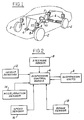
- a control system further comprises suspension control module 6 and steering sensor 8 which is coupled to steering handwheel 10.
- suspension units 4 have only two stable operating states, i.e., in the event that the suspension units are bistable, the previously described sensors and suspension control module may be interconnected and programmed such that the adjustable suspension units will be directed into a firm, as opposed to a soft, position whenever firm operation is indicated by any one of the individual sensors. If, for example, the brake sensor determines that the vehicle's service brakes have been applied at a level exceeding a threshold amount, is is usually desirable to place the adjustable suspension units in a firm position so as to avoid the known phenomenon "brake dive.” Similarly, to avoid pitching of the vehicle, the adjustable suspension units may be placed in the firm position when speed sensor 16 detects that the vehicle has exceeded a given rate of forward velocity. Similar action is indicated in the event that acceleration sensor 14 detects operation of the vehicle's engine in a mode tending to yield vehicle acceleration. Finally, should height sensors 12 detect certain road conditions, such as a rough road surface, it may be desirable to change adjustment of suspension units 4.
- steering sensor 8 includes shutter wheel 20 which is attached to and rotatable with steering shaft 22.
- steering shaft 22 runs between steering handwheel 10 and the steering gear which is connected by means of an appropriate linkage to the steerable wheels of the vehicle.
- Shutter wheel 20 has a plurality of apertures -- in this. case, 40 in number -- which apertures serve to trigger the activity of detectors A and B as shutter wheel 20 is rotated with the steering system of the vehicle. Because there are 40 apertures contained within shutter wheel 20, the steering sensor provides a signal 80 times during one revolution of the steering wheel, and as a result, each of the 80 signals or steps indicates 4.5° of rotation of the steering system.
- Each of detectors A and B includes a light emitting diode (LED) paired with a photo diode.
- the photo diode of each diode pair turns on and off according to the presence or absence of light from its paired LED, which impinges upon the photo diode after passing though one of apertures 24.
- the steering sensor could employ any of a variety of detection schemes other than a photo diode pair. For example, magnetic reed switches or Hall Effect switches could be used.
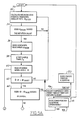
- FIG. 5A and 5B a simplified logic flow diagram for the operation of a control system according to the present invention is shown.
- the computer calculates an instantaneous steering handwheel angular rate ⁇ STEER .
- the control module calculates this instantaneous steering handwheel angular rate by counting the amount of time required for one of apertures 24 to produce a two-state change in one of detectors A or B. Having calculated instantaneous steering handwheel angular rate, ⁇ STEER , the algorithm passes to block 34, wherein ⁇ STEER is compared to an initiation value.
- a return is made to the beginning of the algorithm in the event of a steering reversal because a reversal indicates that it is highly unlikely that the vehicle's driver intended to make a meaningful steering correction; in the event that the driver moves the wheel off its starting point ( ⁇ BASE ) and then back through the starting point in the opposite direction within the space of, say, .3 seconds, this type of movement is more likely indicative of a nervous driver who tends to "saw” the wheel back and forth excessively than it is an indicator of a driver who is purposively attempting to make a vehicular course change.
- the computer transfers to block 44, wherein the difference between ⁇ and ⁇ BASE , which difference equals the excursion angle through which the handwheel has been moved, is compared to a critical reference value.
- the algorithm will adjust the suspension units at block 46.
- the computer will return to block 30 and continue to monitor steering rate.
- the computer will reset the timeout timer which keeps track of the amount of time the suspension has been in the adjusted state. If the computer detects the appropriate condition calling for an adjustment during any subsequent time in which the suspension units are in an adjusted state, it will again reset the timeout timer to register zero elapsed time. All this is possible because the computer performs the operations contained in blocks 30-46 in a background loop which cycles at a rate which substantially exceeds the rate at which the suspension units are adjusted and readjusted.
- the Intel type 8797 microprocessor useful for practicing this invention will cycle through the background loop in no more than 16 milliseconds, whereas the suspension unit will be maintained in an adjusted position for approximately 1.5-2.0 seconds before any further adjustment is performed.
- ⁇ CRITICAL or the critical reference value, will generally depend upon the individual tuning characteristics of the vehicle under consideration.
- ⁇ CRITICAL represents a steering handwheel angle of sufficient magnitude to indicate that an evasive maneuver is likely being attempted by the driver. Such a maneuver could, for example, comprise a sudden lane change necessitated by an obstruction in the roadway.
- ⁇ CRITICAL is selected to be of such a magnitude that there is little doubt that the driver wishes to achieve a rapid and severe change in the vehicle direction, as signified by his severe input into the steering system.
- the computer continues to block 52 wherein the time remaining from the original block of time T D is compared with a nullity. In the event that time remains on T D , the amount of time remaining on the timer will be decremented by a finite amount at block 54 and the algorithm will return to block 40, read steering wheel angle ⁇ once again and continue with the remainder of the algorithm. At the conclusion of the period T D , the computer will set a new time period T D and begin again with the sequence starting with block 30.
- ⁇ THRESHOLD is selected to represent a minimum angle through which the steering handwheel must be turned within time period T D to warrant adjustment of adjustable suspension units 4. In other words, in the event that the driver does not move the steering handwheel through an angle equal to at least the magnitude of ⁇ THRESHOLD , no adjustment will be made and the computer at block 58 will return to the start block.
- ⁇ THRESHOLD is selected to correspond to the minimum steering excursion angle for which an adjustment will produce improved vehicle ride and/or handling characteristics.
- the computer Upon adjusting the suspension units, the computer begins counting time with the previously mentioned timeout timer and will maintain the suspension units in their adjusted state for a predetermined adjustment period of time. As related previously, the computer will return to block in a background loop and continue to monitor steering rate. The timeout timer will be reset to zero elapsed time whenever steering rate conditions indicate that adjustment is warranted. In this manner the control system is able to maintain the adjustable suspension units in an adjusted condition when the vehicle driver is making appropriate steering inputs, without excessive switching from the adjusted to the unadjusted state and vice-versa.
- the suspension units At the conclusion of the predetermined adjustment period, the suspension units will be returned to their original state unless the excursion angle at the conclusion of the predetermined adjustment period exceeds a retention reference value.
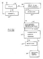
- the retention reference value is embodied in the pseudo position algorithm shown in Figure 6. This pseudo position algorithm is reached by the computer from either block 48 or block 62. For the sake of clarity, it should be noted that the operation of the steering position algorithm alluded to in blocks 48 and 62 will be discussed below.
- sample timer T D is started again with a finite amount of time registered within the timer.
- the amount of time remaining within sample timer T D is compared to a nullity. If the amount of time is not greater than zero, the suspension units will be adjusted and the computer will return to the start block of the main algorithm. If, however, time remains on sample timer T D , the computer will read excursion angle ⁇ at block 78 and compare ⁇ to ⁇ BASE at block 80. In the event that the difference between ⁇ and ⁇ BASE exceeds ⁇ CRITICAL , the suspension units will be maintained at block 84 in their adjusted setting.
- the computer will then transfer to block 86 where T D will be decremented and control transferred to block 74. If the difference between ⁇ and ⁇ BASE does not exceed ⁇ CRITICAL , the suspension units will be adjusted in block 82 and the algorithm will pass to start block 30.
- suspension units will be adjusted at blocks 76 and 82 to a less firm setting because in each case, the situation is identifiable as one in which a less firm setting is desirable.
- a control system may preferably further comprise means for finding an instantaneous steering handwheel angle measured from a dynamically determined steering center position. Such instantaneous handwheel position may be compared with a position reference value. If the position reference value is exceeded, this will indicate that the vehicle driver has moved the steering handwheel to a sufficiently great angle that the adjustable suspension units should be placed in another setting.
- a position reference value is exceeded, this will indicate that the vehicle driver has moved the steering handwheel to a sufficiently great angle that the adjustable suspension units should be placed in another setting.
- the computer will then transfer to block 32 and begin recalculating instantaneous handwheel angular rate. This will enable the computer to control the suspension units with either of the previously described steering algorithms. In other words, the suspension units may be adjusted based upon either handwheel position, or upon the handwheel's angular velocity as defined by the more complicated velocity algorithm.
- the suspension units will be maintained in an adjusted state at the conclusion of a predetermined adjustment period either in the event that the pseudo position algorithm indicates that the adjusted state is required, or in the event that the steering position algorithm indicates that the instantaneous steering handwheel angle exceeds a predetermined position reference value.
- the suspension units could be maintained in an adjusted state at the conclusion of a predetermined time period of adjustment based upon the additional inputs of brake actuation, sensed lateral acceleration, longitudinal acceleration, or other control inputs.
- the predetermined time period for sample timer T D may be adjusted as a function of the forward velocity of the vehicle.
- the magnitudes of the critical and threshold reference values may be adjusted as a function of the forward velocity of the vehicle.
- time T D for the steering system excursion angle to reach the threshold value recognizes the fact that instantaneous steering angular rate may not, in certain cases, produce a reliable indicator of the need for firmer adjusted suspension setting.
- the provision of time period T D and ⁇ THRESHOLD thus allows the use of an average rate calculation in addition to the instantaneous rate or angle capability enabled by the ⁇ CRITICAL portion of the algorithm.
Landscapes
- Engineering & Computer Science (AREA)
- Mechanical Engineering (AREA)
- Vehicle Body Suspensions (AREA)
Applications Claiming Priority (2)
| Application Number | Priority Date | Filing Date | Title |
|---|---|---|---|
| US122313 | 1987-11-18 | ||
| US07/122,313 US4853860A (en) | 1987-11-18 | 1987-11-18 | Control system for adjustable automotive suspension unit |
Publications (3)
| Publication Number | Publication Date |
|---|---|
| EP0317071A2 true EP0317071A2 (de) | 1989-05-24 |
| EP0317071A3 EP0317071A3 (en) | 1990-10-03 |
| EP0317071B1 EP0317071B1 (de) | 1993-11-18 |
Family
ID=22401979
Family Applications (1)
| Application Number | Title | Priority Date | Filing Date |
|---|---|---|---|
| EP88309355A Expired - Lifetime EP0317071B1 (de) | 1987-11-18 | 1988-10-07 | Regelungssystem für eine regelbare Kraftfahrzeugaufhängungseinheit |
Country Status (4)
| Country | Link |
|---|---|
| US (1) | US4853860A (de) |
| EP (1) | EP0317071B1 (de) |
| CA (1) | CA1314959C (de) |
| DE (1) | DE3885716T2 (de) |
Cited By (4)
| Publication number | Priority date | Publication date | Assignee | Title |
|---|---|---|---|---|
| EP0416556A3 (en) * | 1989-09-05 | 1992-09-02 | Toyota Jidosha Kabushiki Kaisha | Fluid pressure type active suspension having variable performance responsive to front to rear wheel steering angle ratio |
| GB2282784A (en) * | 1993-10-08 | 1995-04-19 | Acg France | Vehicle suspension system |
| EP0706905A3 (de) * | 1994-10-14 | 1997-07-09 | Unisia Jecs Corp | Steuerung für die Radaufhängung eines Kraftfahrzeugs |
| WO2004022365A3 (de) * | 2002-09-05 | 2004-05-13 | Continental Teves Ag & Co Ohg | Verfahren zur steuerung und regelung von digital oder analog einstellbaren stossdämpfern |
Families Citing this family (23)
| Publication number | Priority date | Publication date | Assignee | Title |
|---|---|---|---|---|
| JPH0818484B2 (ja) * | 1988-01-25 | 1996-02-28 | 日産自動車株式会社 | サスペンション及び操舵力制御装置 |
| DE3810638C1 (de) * | 1988-03-29 | 1989-08-10 | Boge Ag, 5208 Eitorf, De | |
| DE3818188A1 (de) * | 1988-05-28 | 1989-12-07 | Daimler Benz Ag | Aktives federungssystem |
| US5004265A (en) * | 1988-09-20 | 1991-04-02 | Tokico Ltd. | Suspension system |
| DE3937841A1 (de) * | 1988-11-14 | 1990-05-17 | Atsugi Unisia Corp | System zur erfassung von strassenunebenheit fuer eine aufhaengungssteuerung und kraftfahrzeug-aufhaengungssteuerungsystem, welches die erfasste strassenunebenheit als steuerparameter verwendet |
| JPH02270619A (ja) * | 1989-04-13 | 1990-11-05 | Mitsubishi Electric Corp | ショックアブソーバ制御装置 |
| JPH02303912A (ja) * | 1989-05-17 | 1990-12-17 | Mazda Motor Corp | 車両のサスペンション装置 |
| US5071158A (en) * | 1989-08-28 | 1991-12-10 | Toyota Jidosha Kabushiki Kaisha | Fluid pressure type active suspension responsive to change of rate of change of vehicle height or change of acceleration of vehicle body |
| DE69029628T2 (de) * | 1989-09-11 | 1997-05-22 | Nippon Denso Co | Aufhängungsregelsystem |
| EP0417695B1 (de) * | 1989-09-11 | 1997-12-10 | Toyota Jidosha Kabushiki Kaisha | Aufhängungssteuersystem |
| US5104143A (en) * | 1989-09-27 | 1992-04-14 | Toyota Jidosha Kabushiki Kaisha | Vehicle suspension system with roll control variable according to vehicle speed |
| JPH03136915A (ja) * | 1989-10-24 | 1991-06-11 | Matsushita Electric Ind Co Ltd | サスペンション制御装置 |
| GB2239506B (en) * | 1989-12-08 | 1993-08-25 | Toyota Motor Co Ltd | Suspension control system |
| JP3017512B2 (ja) * | 1990-04-27 | 2000-03-13 | アイシン精機株式会社 | 車輌のロール制御装置 |
| US5321616A (en) * | 1990-08-10 | 1994-06-14 | Matsushita Electric Industrial Co., Ltd. | Vehicle control apparatus |
| JP3083113B2 (ja) * | 1991-12-17 | 2000-09-04 | 株式会社ユニシアジェックス | 車両懸架装置 |
| US5367459A (en) * | 1992-02-10 | 1994-11-22 | Trw Inc. | Apparatus for controlling dampers in a vehicle suspension system |
| JP3080274B2 (ja) * | 1992-09-16 | 2000-08-21 | 株式会社ユニシアジェックス | 車両懸架装置 |
| US5979616A (en) * | 1993-07-12 | 1999-11-09 | Cloud Farm Associates, L.P. | Tilt control apparatus for vehicles |
| US5422810A (en) * | 1994-05-05 | 1995-06-06 | Ford Motor Company | Method and apparatus for determining steering position of automotive steering mechanism |
| US5570287A (en) * | 1994-12-16 | 1996-10-29 | Ford Motor Company | Speed dependent suspension control |
| US5765115A (en) * | 1995-08-04 | 1998-06-09 | Ford Motor Company | Pneumatic tilt stabilization suspension system |
| US7941256B2 (en) * | 2007-10-12 | 2011-05-10 | GM Global Technology Operations LLC | Method for vehicle suspension wear prediction and indication |
Family Cites Families (10)
| Publication number | Priority date | Publication date | Assignee | Title |
|---|---|---|---|---|
| DE2736026C2 (de) * | 1976-08-19 | 1985-10-24 | Honda Giken Kogyo K.K., Tokio/Tokyo | Hydropneumatische Federung für Fahrzeuge |
| JPS5565741A (en) * | 1978-11-10 | 1980-05-17 | Tokico Ltd | Shock absorber |
| US4555126A (en) * | 1982-10-18 | 1985-11-26 | Mazda Motor Corporation | Vehicle suspension system |
| JPS59120509A (ja) * | 1982-12-27 | 1984-07-12 | Toyota Motor Corp | 車両のサスペンシヨン機構におけるシヨツクアブソ−バの減衰力制御装置 |
| EP0115202B1 (de) * | 1982-12-27 | 1988-03-02 | Nippondenso Co., Ltd. | System zum Steuern eines Stossdämpfers |
| JPS59186713A (ja) * | 1983-03-18 | 1984-10-23 | Mazda Motor Corp | 自動車のサスペンシヨン |
| JPS60128011A (ja) * | 1983-12-12 | 1985-07-08 | Nissan Motor Co Ltd | 車両におけるロ−ル剛性制御装置 |
| JPS60203510A (ja) * | 1984-03-27 | 1985-10-15 | Mitsubishi Motors Corp | 自動車の懸架装置 |
| US4697237A (en) * | 1984-11-21 | 1987-09-29 | Mitsubishi Jidosha Kogyo Kabushiki Kaisha | Vehicle suspension apparatus |
| US4621833A (en) * | 1985-12-16 | 1986-11-11 | Ford Motor Company | Control system for multistable suspension unit |
-
1987
- 1987-11-18 US US07/122,313 patent/US4853860A/en not_active Expired - Lifetime
-
1988
- 1988-10-07 DE DE88309355T patent/DE3885716T2/de not_active Expired - Lifetime
- 1988-10-07 EP EP88309355A patent/EP0317071B1/de not_active Expired - Lifetime
- 1988-10-13 CA CA000579998A patent/CA1314959C/en not_active Expired - Lifetime
Cited By (5)
| Publication number | Priority date | Publication date | Assignee | Title |
|---|---|---|---|---|
| EP0416556A3 (en) * | 1989-09-05 | 1992-09-02 | Toyota Jidosha Kabushiki Kaisha | Fluid pressure type active suspension having variable performance responsive to front to rear wheel steering angle ratio |
| GB2282784A (en) * | 1993-10-08 | 1995-04-19 | Acg France | Vehicle suspension system |
| EP0706905A3 (de) * | 1994-10-14 | 1997-07-09 | Unisia Jecs Corp | Steuerung für die Radaufhängung eines Kraftfahrzeugs |
| US5691899A (en) * | 1994-10-14 | 1997-11-25 | Unisia Jecs Corporation | Automotive vehicle suspension control system |
| WO2004022365A3 (de) * | 2002-09-05 | 2004-05-13 | Continental Teves Ag & Co Ohg | Verfahren zur steuerung und regelung von digital oder analog einstellbaren stossdämpfern |
Also Published As
| Publication number | Publication date |
|---|---|
| EP0317071B1 (de) | 1993-11-18 |
| DE3885716D1 (de) | 1993-12-23 |
| CA1314959C (en) | 1993-03-23 |
| EP0317071A3 (en) | 1990-10-03 |
| DE3885716T2 (de) | 1994-03-17 |
| US4853860A (en) | 1989-08-01 |
Similar Documents
| Publication | Publication Date | Title |
|---|---|---|
| US4853860A (en) | Control system for adjustable automotive suspension unit | |
| EP0492782B1 (de) | Vorrichtung und Methode zur dynamischen Ermittlung der Zentripetalkraft einer Fahrzeugs | |
| CA2201196C (en) | Method for determining steering position of automotive steering mechanism | |
| US5787375A (en) | Method for determining steering position of automotive steering mechanism | |
| EP0227343B2 (de) | Steuerung für eine einstellbare Radaufhängung | |
| EP1445130B1 (de) | Verfahren und Vorrichtung zur Fahrwerkregelung eines Kraftfahrzeuges | |
| CA1288513C (en) | Method and apparatus for determining the center position of a vehicular steering system | |
| KR930010592B1 (ko) | 서스펜션제어장치 | |
| GB2253460A (en) | Controlling a vibration damper | |
| JPH02270619A (ja) | ショックアブソーバ制御装置 | |
| US5138554A (en) | Suspension controller | |
| EP0321082B1 (de) | Verfahren und Vorrichtung zur Bestimmung der Mittelstelle eines Fahrzeuglenkungssystems | |
| US6626563B2 (en) | Automatic optical-axis adjusting device for automatically adjusting optical axes of front lights of vehicle with reduced number of signals | |
| US4848791A (en) | Method and apparatus for determining steering position of automotive steering mechanism | |
| US7239951B2 (en) | Apparatus for automatically adjusting direction of light axis of vehicle headlight | |
| CA2028371C (en) | Suspension control apparatus | |
| JPH04303007A (ja) | 車両制御装置 | |
| US6158746A (en) | Suspension control apparatus | |
| JPH09113535A (ja) | 加速度センサの異常検出装置 | |
| KR100556030B1 (ko) | 반능동 현가장치의 댐퍼 감쇠력 선택 방법 | |
| KR100361712B1 (ko) | 액티브써스펜션의제어방법및그장치 | |
| JPH042513A (ja) | サスペンション制御装置 | |
| GB2279425A (en) | Controlling a vibration damper | |
| JPH0435278Y2 (de) | ||
| JPH06270637A (ja) | サスペンション制御装置 |
Legal Events
| Date | Code | Title | Description |
|---|---|---|---|
| PUAI | Public reference made under article 153(3) epc to a published international application that has entered the european phase |
Free format text: ORIGINAL CODE: 0009012 |
|
| AK | Designated contracting states |
Kind code of ref document: A2 Designated state(s): DE FR GB IT |
|
| PUAL | Search report despatched |
Free format text: ORIGINAL CODE: 0009013 |
|
| AK | Designated contracting states |
Kind code of ref document: A3 Designated state(s): DE FR GB IT |
|
| 17P | Request for examination filed |
Effective date: 19901221 |
|
| 17Q | First examination report despatched |
Effective date: 19910422 |
|
| GRAA | (expected) grant |
Free format text: ORIGINAL CODE: 0009210 |
|
| AK | Designated contracting states |
Kind code of ref document: B1 Designated state(s): DE FR GB IT |
|
| ET | Fr: translation filed | ||
| REF | Corresponds to: |
Ref document number: 3885716 Country of ref document: DE Date of ref document: 19931223 |
|
| ITF | It: translation for a ep patent filed | ||
| REG | Reference to a national code |
Ref country code: GB Ref legal event code: 746 Effective date: 19940816 |
|
| PLBE | No opposition filed within time limit |
Free format text: ORIGINAL CODE: 0009261 |
|
| STAA | Information on the status of an ep patent application or granted ep patent |
Free format text: STATUS: NO OPPOSITION FILED WITHIN TIME LIMIT |
|
| 26N | No opposition filed | ||
| REG | Reference to a national code |
Ref country code: FR Ref legal event code: D6 |
|
| REG | Reference to a national code |
Ref country code: FR Ref legal event code: TP Ref country code: FR Ref legal event code: CD |
|
| REG | Reference to a national code |
Ref country code: GB Ref legal event code: IF02 |
|
| PG25 | Lapsed in a contracting state [announced via postgrant information from national office to epo] |
Ref country code: IT Free format text: LAPSE BECAUSE OF NON-PAYMENT OF DUE FEES;WARNING: LAPSES OF ITALIAN PATENTS WITH EFFECTIVE DATE BEFORE 2007 MAY HAVE OCCURRED AT ANY TIME BEFORE 2007. THE CORRECT EFFECTIVE DATE MAY BE DIFFERENT FROM THE ONE RECORDED. Effective date: 20051007 |
|
| REG | Reference to a national code |
Ref country code: FR Ref legal event code: CA Ref country code: FR Ref legal event code: CD |
|
| PGFP | Annual fee paid to national office [announced via postgrant information from national office to epo] |
Ref country code: GB Payment date: 20070918 Year of fee payment: 20 |
|
| PGFP | Annual fee paid to national office [announced via postgrant information from national office to epo] |
Ref country code: DE Payment date: 20071031 Year of fee payment: 20 |
|
| PGFP | Annual fee paid to national office [announced via postgrant information from national office to epo] |
Ref country code: FR Payment date: 20071004 Year of fee payment: 20 |
|
| REG | Reference to a national code |
Ref country code: GB Ref legal event code: PE20 Expiry date: 20081006 |
|
| PG25 | Lapsed in a contracting state [announced via postgrant information from national office to epo] |
Ref country code: GB Free format text: LAPSE BECAUSE OF EXPIRATION OF PROTECTION Effective date: 20081006 |