EP0317110A2 - Verfahren zur gleichzeitigen Erzeugung von elektrischer und thermischer Energie mit niedriger NOx-Produktion - Google Patents
Verfahren zur gleichzeitigen Erzeugung von elektrischer und thermischer Energie mit niedriger NOx-Produktion Download PDFInfo
- Publication number
- EP0317110A2 EP0317110A2 EP88310217A EP88310217A EP0317110A2 EP 0317110 A2 EP0317110 A2 EP 0317110A2 EP 88310217 A EP88310217 A EP 88310217A EP 88310217 A EP88310217 A EP 88310217A EP 0317110 A2 EP0317110 A2 EP 0317110A2
- Authority
- EP
- European Patent Office
- Prior art keywords
- stream
- fuel
- oxygen
- produce
- gaseous
- Prior art date
- Legal status (The legal status is an assumption and is not a legal conclusion. Google has not performed a legal analysis and makes no representation as to the accuracy of the status listed.)
- Granted
Links
- 238000000034 method Methods 0.000 title claims abstract description 32
- 230000008569 process Effects 0.000 title claims abstract description 25
- 239000007789 gas Substances 0.000 claims abstract description 85
- 239000000446 fuel Substances 0.000 claims abstract description 65
- 239000001301 oxygen Substances 0.000 claims abstract description 50
- 229910052760 oxygen Inorganic materials 0.000 claims abstract description 50
- QVGXLLKOCUKJST-UHFFFAOYSA-N atomic oxygen Chemical compound [O] QVGXLLKOCUKJST-UHFFFAOYSA-N 0.000 claims abstract description 46
- 239000003054 catalyst Substances 0.000 claims abstract description 34
- 238000002485 combustion reaction Methods 0.000 claims abstract description 25
- 230000005611 electricity Effects 0.000 claims abstract description 14
- 230000001590 oxidative effect Effects 0.000 claims abstract description 8
- 238000013022 venting Methods 0.000 claims abstract 2
- 230000001351 cycling effect Effects 0.000 claims 2
- 230000000694 effects Effects 0.000 claims 1
- QGZKDVFQNNGYKY-UHFFFAOYSA-N Ammonia Chemical compound N QGZKDVFQNNGYKY-UHFFFAOYSA-N 0.000 description 22
- IJGRMHOSHXDMSA-UHFFFAOYSA-N Atomic nitrogen Chemical compound N#N IJGRMHOSHXDMSA-UHFFFAOYSA-N 0.000 description 22
- VNWKTOKETHGBQD-UHFFFAOYSA-N methane Chemical compound C VNWKTOKETHGBQD-UHFFFAOYSA-N 0.000 description 20
- 238000011282 treatment Methods 0.000 description 14
- MWUXSHHQAYIFBG-UHFFFAOYSA-N Nitric oxide Chemical compound O=[N] MWUXSHHQAYIFBG-UHFFFAOYSA-N 0.000 description 12
- 229910021529 ammonia Inorganic materials 0.000 description 11
- 229910052757 nitrogen Inorganic materials 0.000 description 11
- 238000002347 injection Methods 0.000 description 10
- 239000007924 injection Substances 0.000 description 10
- 239000003345 natural gas Substances 0.000 description 10
- 239000000203 mixture Substances 0.000 description 9
- BASFCYQUMIYNBI-UHFFFAOYSA-N platinum Chemical compound [Pt] BASFCYQUMIYNBI-UHFFFAOYSA-N 0.000 description 9
- 230000009467 reduction Effects 0.000 description 9
- 238000006722 reduction reaction Methods 0.000 description 9
- XLYOFNOQVPJJNP-UHFFFAOYSA-N water Substances O XLYOFNOQVPJJNP-UHFFFAOYSA-N 0.000 description 9
- PNEYBMLMFCGWSK-UHFFFAOYSA-N aluminium oxide Inorganic materials [O-2].[O-2].[O-2].[Al+3].[Al+3] PNEYBMLMFCGWSK-UHFFFAOYSA-N 0.000 description 8
- 239000002918 waste heat Substances 0.000 description 8
- 230000003197 catalytic effect Effects 0.000 description 7
- MGWGWNFMUOTEHG-UHFFFAOYSA-N 4-(3,5-dimethylphenyl)-1,3-thiazol-2-amine Chemical compound CC1=CC(C)=CC(C=2N=C(N)SC=2)=C1 MGWGWNFMUOTEHG-UHFFFAOYSA-N 0.000 description 6
- JCXJVPUVTGWSNB-UHFFFAOYSA-N nitrogen dioxide Inorganic materials O=[N]=O JCXJVPUVTGWSNB-UHFFFAOYSA-N 0.000 description 6
- VYPSYNLAJGMNEJ-UHFFFAOYSA-N Silicium dioxide Chemical compound O=[Si]=O VYPSYNLAJGMNEJ-UHFFFAOYSA-N 0.000 description 5
- 238000006243 chemical reaction Methods 0.000 description 5
- KDLHZDBZIXYQEI-UHFFFAOYSA-N Palladium Chemical compound [Pd] KDLHZDBZIXYQEI-UHFFFAOYSA-N 0.000 description 4
- 230000015572 biosynthetic process Effects 0.000 description 4
- 238000010531 catalytic reduction reaction Methods 0.000 description 4
- 230000004048 modification Effects 0.000 description 4
- 238000012986 modification Methods 0.000 description 4
- 150000002926 oxygen Chemical class 0.000 description 4
- UGFAIRIUMAVXCW-UHFFFAOYSA-N Carbon monoxide Chemical compound [O+]#[C-] UGFAIRIUMAVXCW-UHFFFAOYSA-N 0.000 description 3
- 230000002411 adverse Effects 0.000 description 3
- 239000000567 combustion gas Substances 0.000 description 3
- 238000010304 firing Methods 0.000 description 3
- 239000003546 flue gas Substances 0.000 description 3
- 229910044991 metal oxide Inorganic materials 0.000 description 3
- 150000004706 metal oxides Chemical class 0.000 description 3
- 229910000510 noble metal Inorganic materials 0.000 description 3
- 229910052697 platinum Inorganic materials 0.000 description 3
- PXXKQOPKNFECSZ-UHFFFAOYSA-N platinum rhodium Chemical compound [Rh].[Pt] PXXKQOPKNFECSZ-UHFFFAOYSA-N 0.000 description 3
- 238000011084 recovery Methods 0.000 description 3
- 230000008901 benefit Effects 0.000 description 2
- AMWRITDGCCNYAT-UHFFFAOYSA-L hydroxy(oxo)manganese;manganese Chemical compound [Mn].O[Mn]=O.O[Mn]=O AMWRITDGCCNYAT-UHFFFAOYSA-L 0.000 description 2
- 238000004519 manufacturing process Methods 0.000 description 2
- 229910001092 metal group alloy Inorganic materials 0.000 description 2
- 229910052763 palladium Inorganic materials 0.000 description 2
- 239000000377 silicon dioxide Substances 0.000 description 2
- 239000002699 waste material Substances 0.000 description 2
- QPLDLSVMHZLSFG-UHFFFAOYSA-N Copper oxide Chemical compound [Cu]=O QPLDLSVMHZLSFG-UHFFFAOYSA-N 0.000 description 1
- 239000005751 Copper oxide Substances 0.000 description 1
- 238000010793 Steam injection (oil industry) Methods 0.000 description 1
- 229910052770 Uranium Inorganic materials 0.000 description 1
- 238000003916 acid precipitation Methods 0.000 description 1
- 239000010953 base metal Substances 0.000 description 1
- 238000011955 best available control technology Methods 0.000 description 1
- 230000033228 biological regulation Effects 0.000 description 1
- 150000001875 compounds Chemical class 0.000 description 1
- 239000000356 contaminant Substances 0.000 description 1
- 229910000431 copper oxide Inorganic materials 0.000 description 1
- QDOXWKRWXJOMAK-UHFFFAOYSA-N dichromium trioxide Chemical compound O=[Cr]O[Cr]=O QDOXWKRWXJOMAK-UHFFFAOYSA-N 0.000 description 1
- -1 e.g. Substances 0.000 description 1
- 238000010438 heat treatment Methods 0.000 description 1
- 230000001965 increasing effect Effects 0.000 description 1
- 230000007246 mechanism Effects 0.000 description 1
- 238000013021 overheating Methods 0.000 description 1
- 238000007254 oxidation reaction Methods 0.000 description 1
- 230000001105 regulatory effect Effects 0.000 description 1
- 230000001629 suppression Effects 0.000 description 1
- 238000011144 upstream manufacturing Methods 0.000 description 1
Images
Classifications
-
- F—MECHANICAL ENGINEERING; LIGHTING; HEATING; WEAPONS; BLASTING
- F01—MACHINES OR ENGINES IN GENERAL; ENGINE PLANTS IN GENERAL; STEAM ENGINES
- F01K—STEAM ENGINE PLANTS; STEAM ACCUMULATORS; ENGINE PLANTS NOT OTHERWISE PROVIDED FOR; ENGINES USING SPECIAL WORKING FLUIDS OR CYCLES
- F01K23/00—Plants characterised by more than one engine delivering power external to the plant, the engines being driven by different fluids
- F01K23/02—Plants characterised by more than one engine delivering power external to the plant, the engines being driven by different fluids the engine cycles being thermally coupled
- F01K23/06—Plants characterised by more than one engine delivering power external to the plant, the engines being driven by different fluids the engine cycles being thermally coupled combustion heat from one cycle heating the fluid in another cycle
- F01K23/10—Plants characterised by more than one engine delivering power external to the plant, the engines being driven by different fluids the engine cycles being thermally coupled combustion heat from one cycle heating the fluid in another cycle with exhaust fluid of one cycle heating the fluid in another cycle
- F01K23/103—Plants characterised by more than one engine delivering power external to the plant, the engines being driven by different fluids the engine cycles being thermally coupled combustion heat from one cycle heating the fluid in another cycle with exhaust fluid of one cycle heating the fluid in another cycle with afterburner in exhaust boiler
-
- F—MECHANICAL ENGINEERING; LIGHTING; HEATING; WEAPONS; BLASTING
- F22—STEAM GENERATION
- F22B—METHODS OF STEAM GENERATION; STEAM BOILERS
- F22B1/00—Methods of steam generation characterised by form of heating method
- F22B1/02—Methods of steam generation characterised by form of heating method by exploitation of the heat content of hot heat carriers
- F22B1/18—Methods of steam generation characterised by form of heating method by exploitation of the heat content of hot heat carriers the heat carrier being a hot gas, e.g. waste gas such as exhaust gas of internal-combustion engines
- F22B1/1861—Waste heat boilers with supplementary firing
-
- F—MECHANICAL ENGINEERING; LIGHTING; HEATING; WEAPONS; BLASTING
- F23—COMBUSTION APPARATUS; COMBUSTION PROCESSES
- F23C—METHODS OR APPARATUS FOR COMBUSTION USING FLUID FUEL OR SOLID FUEL SUSPENDED IN A CARRIER GAS OR AIR
- F23C6/00—Combustion apparatus characterised by the combination of two or more combustion chambers or combustion zones, e.g. for staged combustion
- F23C6/04—Combustion apparatus characterised by the combination of two or more combustion chambers or combustion zones, e.g. for staged combustion in series connection
- F23C6/042—Combustion apparatus characterised by the combination of two or more combustion chambers or combustion zones, e.g. for staged combustion in series connection with fuel supply in stages
-
- F—MECHANICAL ENGINEERING; LIGHTING; HEATING; WEAPONS; BLASTING
- F23—COMBUSTION APPARATUS; COMBUSTION PROCESSES
- F23C—METHODS OR APPARATUS FOR COMBUSTION USING FLUID FUEL OR SOLID FUEL SUSPENDED IN A CARRIER GAS OR AIR
- F23C9/00—Combustion apparatus characterised by arrangements for returning combustion products or flue gases to the combustion chamber
-
- F—MECHANICAL ENGINEERING; LIGHTING; HEATING; WEAPONS; BLASTING
- F23—COMBUSTION APPARATUS; COMBUSTION PROCESSES
- F23J—REMOVAL OR TREATMENT OF COMBUSTION PRODUCTS OR COMBUSTION RESIDUES; FLUES
- F23J15/00—Arrangements of devices for treating smoke or fumes
- F23J15/006—Layout of treatment plant
-
- F—MECHANICAL ENGINEERING; LIGHTING; HEATING; WEAPONS; BLASTING
- F23—COMBUSTION APPARATUS; COMBUSTION PROCESSES
- F23J—REMOVAL OR TREATMENT OF COMBUSTION PRODUCTS OR COMBUSTION RESIDUES; FLUES
- F23J2215/00—Preventing emissions
- F23J2215/20—Sulfur; Compounds thereof
-
- F—MECHANICAL ENGINEERING; LIGHTING; HEATING; WEAPONS; BLASTING
- F23—COMBUSTION APPARATUS; COMBUSTION PROCESSES
- F23J—REMOVAL OR TREATMENT OF COMBUSTION PRODUCTS OR COMBUSTION RESIDUES; FLUES
- F23J2219/00—Treatment devices
- F23J2219/10—Catalytic reduction devices
Definitions
- This invention relates to cogeneration and is more particularly concerned with a cogeneration process which ensures low NOX content of the evolved gases.
- oxides of nitrogen are one of the principal contaminants emitted by combustion processes.
- the high temperatures at the burner result in the fixation of some oxides of nitrogen.
- These compounds are found in stack gases mainly as nitric oxide (NO) with lesser amounts of nitrogen dioxide (NO2) and only traces of other oxides. Since nitric oxide (NO) continues to oxidize to nitrogen dioxide (NO2) in the air at ordinary temperatures, there is no way to predict with accuracy the amounts of each separately in vented gases at a given time.
- NOX oxygen-oxides of nitrogen
- Cogeneration is a process which emits stack gases of undesirable NOX content.
- Cogeneration is the simultaneous production of both useful thermal energy (usually steam) and electrical energy from one source of fuel.
- One or more gas turbines followed by a waste heat boiler using natural gas as fuel for both the turbines and to heat the exhaust gases from the turbines represent a typical system.
- NOX emissions generated with the combined firing cycle.
- Cogeneration plants using conventional gas turbines and auxiliary fuel fired heat recovery boilers to produce electricity and steam are being subjected to stringent NO X emission standards requiring levels below the 150 ppm range.
- New Source Performance Standards (NSPS) strictly limit NOX emission.
- NPS New Source Performance Standards
- Injection methods include injection of either water or steam into the combustion zone to lower the flame temperature and retard the formation of NOX, since the amount of NOX formed generally increases with increasing temperatures, or injection of ammonia to selectively reduce NOX.
- Equipment modifications include modifications to the burner or firebox to reduce the formation of NOX. Although these methods do reduce the level of NOX, each has its own drawbacks. Combustion equipment modification affects the performance of the turbines and limits the range of operations. Moreover, cogeneration plants of this type employed for generating electric power and steam are being subjected to increasingly stringent NOX emission standards, and a satisfactory emission control system is required to minimize the undesirable emissions exhausted to the atmosphere. A selective catalytic reduction system is presently considered by some authorities to be the best available control technology for the reduction of NOX from the exhaust gas of a cogeneration plant, and as a consequence is required equipment.
- the turbine exhaust temperature of most gas turbine cogeneration plants, at full or rated load of the gas turbine engine, is conventionally between approximately 775°F and 1050°F. Since the exhaust gas temperature is above the optimum temperature range of the usual selective catalytic reduction system, it is necessary to reduce the temperature of the exhaust gas stream before it passes through the system.
- Current practice is to provide steam superheater and/or steam generating tubes upstream of the system to withdraw heat from the exhaust gas stream to cool the gas to a preselected desired nominal temperature before it passes through the system. This imposes various operating limitations on the cogeneration plant which either seriously limit the operating range of the gas turbine engine or require an undesirable exhaust gas bypass or other mechanism for diverting a portion of the exhaust gas stream. Where supplementary firing is provided to increase steam production, the supplementary firing is conventionally carried out with an excess of air.
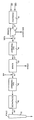
- a cogeneration system wherein electrical power is generated by a gas turbine, the gaseous effluent together with sufficient additional fuel to produce a fuel-rich, fuel-air mixture is either combusted, e.g. in an afterburner, or is catalytically treated in a reducing atmosphere and is then fed to a boiler to generate steam. Air is added to the gaseous effluent from the boiler to form a lean fuel-air mixture, and this mixture is passed over an oxidizing catalyst, with the resultant gas stream then passing to an economizer or low pressure waste boiler for substantial recovery of its remaining heat content, and the gas, now meeting NOX emission standards, is thereafter vented to the atmosphere.
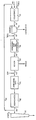
- at least some of the final effluent i.e., the effluent from the economizer or low-pressure waste-heat boiler, is circulated to the combustor supplying gas to the turbine.
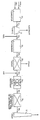
- the reference numeral 10 designates a combustor or burner which receives fuel such as gas or naptha and compressed air and burns the air-fuel mixture to produce a gaseous effluent which passes into a duct 12 which directs it to a gas turbine 14 which is coupled to a generator (not shown), to produce electrical power.
- the turbine exhaust gas leaves through a duct 16 into which are introduced further amounts of fuel, the amount depending upon the fuel-air ratio in the exhaust gas from the turbine. Since there will be ample air, only fuel is injected at this point.
- the amount of fuel added is selected so that there will be 10 to 25% stoichiometric excess fuel relative to the available oxygen in the exhaust gas from the gas turbine.
- the fuel added is ordinarily gas, such as natural gas.
- the exhaust gaseous stream from the turbine is treated, i.e., has fuel added to it, to produce a fuel-rich, fuel-air mixture containing 10% to 25% excess of fuel over the oxygen stoichiometrically present.
- the thus-treated exhaust gas from the turbine is then passed to an afterburner 18 wherein it is burned at a temperature of about 2000 to 3000°F.
- a residence time of 0.5 seconds is required to ensure that the desired reduction of the oxides of nitrogen will occur.
- a greater residence time can be employed, e.g., 1 minute or more, but serves no useful purpose.
- the afterburner of unit 18 can be replaced by a reducing catalyst treatment.
- the fuel-enriched exhaust gas from the turbine at about 800°F. to about 1050°F. is passed to a catalytic treatment zone 18, wherein the fuel-rich stream is passed over a reducing catalyst, e.g., platinum-rhodium in the zero-valent state supported on a carrier such as alumina, silica or a metal alloy.
- a reducing catalyst e.g., platinum-rhodium in the zero-valent state supported on a carrier such as alumina, silica or a metal alloy.
- Catalyst volumes will vary depending on the particular catalyst used. Ordinarily, the quantity of catalyst and the flow rate are such that the space velocity is typically in the range of 30,000 to 50,000 hr. ⁇ 1 preferably 30,000 to 40,000 hr. ⁇ 1.
- the afterburner 18 when used and the waste-heat boiler 22 can, of course, be combined in the form of a fuel-burning boiler wherein the added fuel and the exhaust gas from the turbine are combusted to produce steam directly.
- the boiler 22 discharges a waste effluent gas into a duct 24. Because of the addition of fuel to the duct 16 and the burning or catalytic treatment of the turbine exhaust gas in the presence of this fuel with significantly less than the stoichiometric requirement of oxygen, i.e., under reducing conditions, the exhaust gas in duct 24 from the boiler 22 contains not only combustion gases, but some unburned fuel. It is, however, low in NOX and the treatment of the gases flowing through the system has brought about a reduction of any NOX formed, or a suppression of the formation of the NOX, without the use of ammonia or like treating system widely used in the prior art.
- air is added to the stream in conduit 24 and the resulting gaseous stream is passed to a gas treatment unit 26 wherein the gas stream is passed over an oxidizing catalyst.
- the amount of air is added in an amount relative to the stream in conduit 24 such that the resulting stream will contain oxygen soichiometrically in excess of the amount needed to burn any fuel which may be present in the stream, e.g., 10% to 50% excess.
- products at the boiler discharge temperature e.g., 500° - 600°F are mixed with air and passed over an oxidizing catalyst.
- noble metal catalyst such as platinum or palladium or base metal oxides, such as copper oxide, chrome oxide, or manganese oxide, or the like, may be used for this purpose.
- the noble metal catalysts e.g., platinum or palladium catalysts, are most suitable the noble metals deposited in the zero valent state upon a support, such as alumina, silica, kiesel-guhr, or a metal alloy, and the like.
- the metal oxide catalysts are also most suitably the metal oxides supported on supports of this character. The making of such catalysts is well known to persons skilled in the art. Catalyst volumes will vary depending on the particular catalyst used.
- the quantity of catalyst and the flow rate are such that the space velocity is typically in the range of 30,000 to 50,000 hr. ⁇ 1.
- Data indicate that NOX levels in the parts per billion range can be realized by the combined reduction-oxidation operations of this invention.
- the oxidized gaseous effluent from the unit 26 passes into a conduit 27 which leads an economizer or a low-pressure, waste-heat boiler, or the like, indicated at 28, and the heat content of the oxidized gaseous effluent is extracted to the maximum amount economically feasible.
- the cooled gas at a temperature of about 300 to 400°F is then discharged through an outlet conduit 30 into a stack 32 and vented to the atmosphere with the assurance that the vented effluent will complex with NOX emission standards. It will have a NOX content of less than 50 ppm.
- effluent e.g. flue gas
- an appropriate valve controls the recycle rate. At least a portion of the effluent is diverted into line 36 which conducts the diverted effluent to combustor 10.
- the oxygen content of the turbine exhaust will be significantly lower, which will correspondingly lower the fuel requirement for the subsequent reducing step.
- the quantity of effluent diverted can vary but, for best results the quantity of recycled effluent, e.g. flue gas, added to the combustor will be such as is required to produce a turbine exhaust at a temperature of 800-1000°F. with 1-2% 02.
- the gas turbine 14 furnishes the total of the combustion-supporting air for the afterburner 18, if one is used, and that care is taken to maintain reducing conditions during this combustion, or during the catalytic treatment at 18, by appropriate control of the supply of fuel.
- Another aspect of the invention is that heat recovery in a turbine cogeneration system is maximized in a highly economical manner and that NOX content is kept at a minimum without resort to elaborate equipment reconstruction, without heat loss by injecting water into the exhaust gases from the turbine, and without ammonia injection or catalytic reduction in the presence of ammonia.
- gas treatment units can be any containers adapted for gas passage and containing an appropriate catalyst.
- the turbine 14, for example can be of the type which produces substantially the same quantity of exhaust gas throughout the range of its operation, as, for example, a single cycle, single shaft gas turbine.
- Minimizing the formation of oxides of nitrogen in cogeneration offers several advantages over the current state of the art. This process does not require that a potentially obnoxious gas, such as ammonia, be injected into the system; the reaction conditions do not require that a narrowly-controlled temperature be maintained for the reduction of oxides of nitrogen to occur; the operating conditions are compatible with conventional cogeneration conditions; and greater NOX reduction efficiencies can be achieved.
- a potentially obnoxious gas such as ammonia
- a combustor is fed with natural gas to produce a combustible mixture which is combusted at a temperature of 2000°F. to produce a stream of combustion products which are fed to a turbine to generate electricity.
- the exhaust stream from the turbine at a temperature of 800°F. contains about 14% oxygen.
- Natural gas at ambient temperature is injected into this exhaust stream to give the resultant stream a fuel content such that the fuel is 10% in stoichiometric excess relative to the oxygen present.
- the resultant stream is then combusted at a temperature of 3300°F. and since the fuel is in excess, the combustion takes place in a reducing atmosphere.
- Heat present in the combustion products is at least partially converted into steam by heat exchange with water, e.g., in boiler tubes, and the resulting gaseous stream, which is of course, oxygen depleted, has a temperature of 500°F.
- water e.g., in boiler tubes
- oxygen depleted oxygen depleted
- air at ambient temperature in an amount such that the resultant stream has an oxygen content which is 50% stoichiometrically in excess relative to any fuel present in the oxygen-depleted stream to which the air is added.
- the resultant oxygen-rich stream is then fed through a bed of platinum black supported on alumina with a space velocity of 50,000 hr. ⁇ 1. At this point the gaseous stream being processed has a temperature of 500°F. This temperature increases across the catalyst bed to about 750°F.
- Heat is then extracted by appropriate heat exchange to leave a final stream to be vented having a temperature of about 350°F. and a NOX content of less than 50ppm.
- a combustor is fed with natural gas to produce a combustible mixture which is combusted at a temperature of 800-1000°F. to produce a stream of combustion products which are fed to a turbine to generate electricity.
- the exhaust stream from the turbine at a temperature of 800°F. contains about 14% oxygen.
- Natural gas at ambient temperature is injected into this exhaust stream to give the resultant stream a fuel content such that the fuel is 10% in stoichiometric excess relative to the oxygen present.
- the resultant stream is then passed over a platinum-rhodium catalyst ( ⁇ 1% supported on alumina) at a space velocity of 40,000 hr. ⁇ 1 and, since the fuel is in excess, the treatment takes place in a reducing atmosphere.
- This catalytic treatment causes the temperature of the stream to rise to 1400°F.
- Heat present in the combustion products is at least partially converted into steam by heat exchange with water, e.g., in boiler tubes, and the resulting gaseous stream, which is of course, oxygen depleted, has a temperature of 500°F.
- To this oxygen-depleted stream is then added air at ambient temperature in an amount such that the resultant stream has an oxygen content which is 25-50% stoichiometrically in excess relative to any fuel present in the oxygen depleted stream to which the air is added.
- the resultant oxygen-rich stream is then fed through a bed of platinum (1 ⁇ % supported on alumina) with a space velocity of 50,000 hr. ⁇ 1.
- the gaseous stream being processed has a temperature of 500°F. This temperature increases across the catalyst bed to about 750°F. Heat is then extracted by appropriate heat exchange to leave a final stream to be vented having a temperature of about 350°F. and a NOX content of less than 50 ppm.
- a combustor is fed with natural gas and combustion air to produce a combustible mixture which is combusted at a temperature of 1700°F. to produce a stream of combustion products which are fed to a turbine to generate electricity.
- the exhaust stream from the turbine at a temperature of 800-1000°F. contains about 14% oxygen.
- Natural gas at ambient temperature is injected into this exhaust stream to give the resultant stream a fuel content such that the fuel is 10% in stoichiometric excess relative to the oxygen present.
- the resultant stream is then combusted at a temperature of 3300°F. and, since the fuel is in excess, the combustion takes place in a reducing atmosphere.
- Heat present in the combustion products is at least partially converted into steam by heat exchange with water, e.g., in boiler tubes, and the resulting gaseous stream, which is of course, oxygen depleted, has a temperature of 500°F.
- water e.g., in boiler tubes
- oxygen depleted oxygen depleted
- air at ambient temperature in an amount such that the resultant stream has an oxygen content which is 25-50% stoichiometrically in excess relative to any fuel present in the oxygen-depleted stream to which the air is added.
- the resultant oxygen-rich stream is then fed through a bed of platinum black ( ⁇ 1% supported on alumina) with a space velocity of 50,000 hr. ⁇ 1. At this point the gaseous stream being processed has a temperature of 500°F.
- This temperature increases across the catalyst bed to about 750°F. Heat is then extracted by appropriate heat exchange to leave a final stream to be vented having a temperature of about 350°F. and a NOX content of less than 50 ppm.
- 60-65% of the final effluent stream is cycled to provide a ratio of 1.75:1.0 of recycled flue gas to combustion gases.
- a combustor is fed with natural gas to produce a combustible mixture which is combusted at a temperature of 1700°F. to produce a stream of combustion products which are fed to a turbine to generate electricity.
- the exhaust stream from the turbine at a temperature of 800°F. contains about 14% oxygen.
- Natural gas at ambient temperature is injected into this exhaust stream to give the resultant stream a fuel content such that the fuel is 10% in stoichiometric excess relative to the oxygen present.
- the resultant steam is then passed over platinum-rhodium ( ⁇ 1% supported on alumina) at a space velocity of 30,000 hr. ⁇ 1 and, since the fuel is in excess, the treatment takes place in a reducing atmosphere.
- This catalytic treatment causes the temperature of the stream to rise to 1400°F.
- Heat present in the combustion products is at least partially converted into steam by heat exchange with water, e.g., in boiler tubes, and the resulting gaseous stream, which is of course, oxygen depleted, has a temperature of 500°F.
- To this oxygen-depleted stream is then added air at ambient temperature in an amount such that the resultant stream has an oxygen content which is 50% stoichiometrically in excess relative to any fuel present in the oxygen-depleted stream to which the air is added.
- the resultant oxygen-rich stream is then fed through a bed of platinum black ( ⁇ 1% supported on alumina) with a space velocity of 50,000 hr. ⁇ 1.
- the gaseous stream being processed has a temperature of 500°F. This temperature increases across the catalyst bed to about 750°F. Heat is then extracted by appropriate heat exchange to leave a final stream to be vented having a temperature of about 350°F. and a NOX content of less than 50 ppm.
- 65% of the final effluent stream is cycled to provide a ratio of 1.75:1.0 of cycled effluent to combustion gases.
Landscapes
- Engineering & Computer Science (AREA)
- Mechanical Engineering (AREA)
- General Engineering & Computer Science (AREA)
- Chemical & Material Sciences (AREA)
- Combustion & Propulsion (AREA)
- Life Sciences & Earth Sciences (AREA)
- Sustainable Development (AREA)
- Sustainable Energy (AREA)
- Physics & Mathematics (AREA)
- Thermal Sciences (AREA)
- Chimneys And Flues (AREA)
- Exhaust Gas Treatment By Means Of Catalyst (AREA)
Applications Claiming Priority (6)
| Application Number | Priority Date | Filing Date | Title |
|---|---|---|---|
| US252690 | 1981-04-09 | ||
| US252778 | 1981-04-10 | ||
| US07/122,067 US4811555A (en) | 1987-11-18 | 1987-11-18 | Low NOX cogeneration process |
| US122067 | 1987-11-18 | ||
| US07/252,690 US4930305A (en) | 1987-11-18 | 1988-10-03 | Low NOX cogeneration process |
| US07/252,778 US4936088A (en) | 1987-11-18 | 1988-10-03 | Low NOX cogeneration process |
Publications (3)
| Publication Number | Publication Date |
|---|---|
| EP0317110A2 true EP0317110A2 (de) | 1989-05-24 |
| EP0317110A3 EP0317110A3 (en) | 1990-03-07 |
| EP0317110B1 EP0317110B1 (de) | 1992-03-04 |
Family
ID=27382723
Family Applications (1)
| Application Number | Title | Priority Date | Filing Date |
|---|---|---|---|
| EP19880310217 Expired EP0317110B1 (de) | 1987-11-18 | 1988-10-31 | Verfahren zur gleichzeitigen Erzeugung von elektrischer und thermischer Energie mit niedriger NOx-Produktion |
Country Status (4)
| Country | Link |
|---|---|
| EP (1) | EP0317110B1 (de) |
| JP (1) | JPH01193513A (de) |
| DE (1) | DE3868865D1 (de) |
| ES (1) | ES2030871T3 (de) |
Cited By (8)
| Publication number | Priority date | Publication date | Assignee | Title |
|---|---|---|---|---|
| DE3905775A1 (de) * | 1989-02-24 | 1990-08-30 | Kat Tec Ges Fuer Katalysatorte | Verfahren und vorrichtung zur reduzierung von schadstoffen eines verbrennungsverfahrens mit oxidations-wabenkatalysatoren und katalysatoren mit entschwefelungseigenschaften und abgasrueckfuehrung |
| EP0385690A3 (de) * | 1989-03-03 | 1991-01-02 | Radian Corporation | Verbrennungsverfahren mit vermindertem NOx-Ausstoss |
| US5810901A (en) * | 1992-11-27 | 1998-09-22 | Pilkington Glass Limited | Method for reducing NOx emissions from a regenerative glass furnace |
| US5820651A (en) * | 1992-11-27 | 1998-10-13 | Pilkington Glass Limited | Method for reducing CO emissions from a regenerative glass furnace |
| EP0899505A3 (de) * | 1997-08-29 | 2001-10-04 | Mitsubishi Heavy Industries, Ltd. | Kombikraftwerk |
| CN108350806A (zh) * | 2015-11-20 | 2018-07-31 | 西门子股份公司 | 燃气轮机系统 |
| WO2023004073A1 (en) * | 2021-07-21 | 2023-01-26 | Modern Electron, Inc. | Combustion systems including heat modules, and associated devices and methods |
| US12617674B2 (en) | 2024-10-24 | 2026-05-05 | Modern Hydrogen, Inc. | Pyrolysis and combustion control in pyrolysis reactors, and associated systems and methods |
Family Cites Families (4)
| Publication number | Priority date | Publication date | Assignee | Title |
|---|---|---|---|---|
| EP0047346B1 (de) * | 1980-09-01 | 1989-03-15 | John Zink Company | Entfernung von Stickoxiden und Wärmeerzeugung in einer kombinierten Vorrichtung |
| US4405587A (en) * | 1982-02-16 | 1983-09-20 | Mcgill Incorporated | Process for reduction of oxides of nitrogen |
| US4572110A (en) * | 1985-03-01 | 1986-02-25 | Energy Services Inc. | Combined heat recovery and emission control system |
| US4706612A (en) * | 1987-02-24 | 1987-11-17 | Prutech Ii | Turbine exhaust fed low NOx staged combustor for TEOR power and steam generation with turbine exhaust bypass to the convection stage |
-
1988
- 1988-10-31 ES ES88310217T patent/ES2030871T3/es not_active Expired - Lifetime
- 1988-10-31 EP EP19880310217 patent/EP0317110B1/de not_active Expired
- 1988-10-31 DE DE8888310217T patent/DE3868865D1/de not_active Expired - Fee Related
- 1988-11-17 JP JP63291057A patent/JPH01193513A/ja active Pending
Cited By (15)
| Publication number | Priority date | Publication date | Assignee | Title |
|---|---|---|---|---|
| DE3905775A1 (de) * | 1989-02-24 | 1990-08-30 | Kat Tec Ges Fuer Katalysatorte | Verfahren und vorrichtung zur reduzierung von schadstoffen eines verbrennungsverfahrens mit oxidations-wabenkatalysatoren und katalysatoren mit entschwefelungseigenschaften und abgasrueckfuehrung |
| EP0384295A3 (de) * | 1989-02-24 | 1990-12-05 | Kat- Tec Gesellschaft Für Katalysatortechnik Mbh | Verfahren und Vorrichtung zur Reduzierung von Schadstoffen eines Verbrennungsverfahrens mit Oxidations-Wabenkatalysatoren und Katalysatoren mit Entschwefelungseigenschaften und Abgasrückführung |
| EP0385690A3 (de) * | 1989-03-03 | 1991-01-02 | Radian Corporation | Verbrennungsverfahren mit vermindertem NOx-Ausstoss |
| US5837028A (en) * | 1992-11-27 | 1998-11-17 | Pilkington Glass Limited | Method for reducing CO emissions from a regenerative glass furnace |
| US5820651A (en) * | 1992-11-27 | 1998-10-13 | Pilkington Glass Limited | Method for reducing CO emissions from a regenerative glass furnace |
| US5833730A (en) * | 1992-11-27 | 1998-11-10 | Pilkington Glass Limited | Method for reducing NOx emissions from a regenerative glass furnace |
| US5810901A (en) * | 1992-11-27 | 1998-09-22 | Pilkington Glass Limited | Method for reducing NOx emissions from a regenerative glass furnace |
| US5849059A (en) * | 1992-11-27 | 1998-12-15 | Pilkington Glass Limited | Method for reducing NOx emissions from a regenerative glass furnace |
| US5851256A (en) * | 1992-11-27 | 1998-12-22 | Pilkington Glass Limited | Method for reducing NOx emissions from a regenerative glass furnace |
| EP0899505A3 (de) * | 1997-08-29 | 2001-10-04 | Mitsubishi Heavy Industries, Ltd. | Kombikraftwerk |
| CN108350806A (zh) * | 2015-11-20 | 2018-07-31 | 西门子股份公司 | 燃气轮机系统 |
| CN108350806B (zh) * | 2015-11-20 | 2023-05-26 | 西门子能源环球有限责任两合公司 | 燃气轮机系统 |
| WO2023004073A1 (en) * | 2021-07-21 | 2023-01-26 | Modern Electron, Inc. | Combustion systems including heat modules, and associated devices and methods |
| US12253259B2 (en) | 2021-07-21 | 2025-03-18 | Modern Hydrogen, Inc. | Combustion systems including heat modules, and associated devices and methods |
| US12617674B2 (en) | 2024-10-24 | 2026-05-05 | Modern Hydrogen, Inc. | Pyrolysis and combustion control in pyrolysis reactors, and associated systems and methods |
Also Published As
| Publication number | Publication date |
|---|---|
| JPH01193513A (ja) | 1989-08-03 |
| EP0317110B1 (de) | 1992-03-04 |
| DE3868865D1 (de) | 1992-04-09 |
| EP0317110A3 (en) | 1990-03-07 |
| ES2030871T3 (es) | 1992-11-16 |
Similar Documents
| Publication | Publication Date | Title |
|---|---|---|
| EP0648313B1 (de) | Verfahren und system zur gleichzeitigen erzeugung elektrischer und thermischer energie mit geringer nox-produktion | |
| US4811555A (en) | Low NOX cogeneration process | |
| EP0521949B1 (de) | VERFAHREN UND SYSTEM ZUR GLEICHZEITIGEN ERZEUGUNG ELEKTRISCHER UND THERMISCHER ENERGIE MIT GERINGER NOx-PRODUKTION | |
| US4936088A (en) | Low NOX cogeneration process | |
| US5178101A (en) | Low NOx combustion process and system | |
| EP0899505B1 (de) | Kombikraftwerk | |
| US5500194A (en) | Hybrid low NOx process for destruction of bound nitrogen compounds | |
| JP2000240924A (ja) | 鉄鋼作業ガスの処理方法 | |
| US4930305A (en) | Low NOX cogeneration process | |
| EP0317110A2 (de) | Verfahren zur gleichzeitigen Erzeugung von elektrischer und thermischer Energie mit niedriger NOx-Produktion | |
| US4951579A (en) | Low NOX combustion process | |
| EP2686525B1 (de) | Wärmekraftanlage | |
| KR200199659Y1 (ko) | 보일러 배기가스 정화장치 | |
| JPS59191809A (ja) | 蒸気−ガス複合サイクルの低NOx化法およびその装置 | |
| JPH08312310A (ja) | 廃棄物発電システム | |
| JPH09178145A (ja) | 廃棄物発電システム | |
| JPH09250308A (ja) | ディーゼルエンジンを用いたコンバインド発電設備 | |
| RU2293254C2 (ru) | Способ очистки продуктов сгорания газообразного топлива от токсичных веществ | |
| JPH0972204A (ja) | 廃棄物発電システム | |
| JPH09178146A (ja) | 廃棄物発電システム | |
| JPH05272731A (ja) | ゴミ焼却装置 | |
| JPS60159512A (ja) | 原動機の排ガス脱硝方法 | |
| JPH046303A (ja) | 燃焼排ガス循環炉および燃焼方法 | |
| JPH07103409A (ja) | 炉内脱硝式追焚システム | |
| JPH09184609A (ja) | 焼却炉における廃熱発電システム |
Legal Events
| Date | Code | Title | Description |
|---|---|---|---|
| PUAI | Public reference made under article 153(3) epc to a published international application that has entered the european phase |
Free format text: ORIGINAL CODE: 0009012 |
|
| AK | Designated contracting states |
Kind code of ref document: A2 Designated state(s): DE ES FR GB IT NL |
|
| PUAL | Search report despatched |
Free format text: ORIGINAL CODE: 0009013 |
|
| AK | Designated contracting states |
Kind code of ref document: A3 Designated state(s): DE ES FR GB IT NL |
|
| 17P | Request for examination filed |
Effective date: 19900626 |
|
| 17Q | First examination report despatched |
Effective date: 19901116 |
|
| GRAA | (expected) grant |
Free format text: ORIGINAL CODE: 0009210 |
|
| AK | Designated contracting states |
Kind code of ref document: B1 Designated state(s): DE ES FR GB IT NL |
|
| REF | Corresponds to: |
Ref document number: 3868865 Country of ref document: DE Date of ref document: 19920409 |
|
| ITF | It: translation for a ep patent filed | ||
| ET | Fr: translation filed | ||
| REG | Reference to a national code |
Ref country code: ES Ref legal event code: FG2A Ref document number: 2030871 Country of ref document: ES Kind code of ref document: T3 |
|
| PLBE | No opposition filed within time limit |
Free format text: ORIGINAL CODE: 0009261 |
|
| STAA | Information on the status of an ep patent application or granted ep patent |
Free format text: STATUS: NO OPPOSITION FILED WITHIN TIME LIMIT |
|
| 26N | No opposition filed | ||
| PGFP | Annual fee paid to national office [announced via postgrant information from national office to epo] |
Ref country code: ES Payment date: 19931005 Year of fee payment: 6 |
|
| PGFP | Annual fee paid to national office [announced via postgrant information from national office to epo] |
Ref country code: GB Payment date: 19931021 Year of fee payment: 6 |
|
| PGFP | Annual fee paid to national office [announced via postgrant information from national office to epo] |
Ref country code: FR Payment date: 19931022 Year of fee payment: 6 |
|
| PGFP | Annual fee paid to national office [announced via postgrant information from national office to epo] |
Ref country code: NL Payment date: 19931031 Year of fee payment: 6 |
|
| PGFP | Annual fee paid to national office [announced via postgrant information from national office to epo] |
Ref country code: DE Payment date: 19931230 Year of fee payment: 6 |
|
| PG25 | Lapsed in a contracting state [announced via postgrant information from national office to epo] |
Ref country code: GB Effective date: 19941031 |
|
| PG25 | Lapsed in a contracting state [announced via postgrant information from national office to epo] |
Ref country code: ES Free format text: LAPSE BECAUSE OF THE APPLICANT RENOUNCES Effective date: 19941102 |
|
| PG25 | Lapsed in a contracting state [announced via postgrant information from national office to epo] |
Ref country code: NL Effective date: 19950501 |
|
| NLV4 | Nl: lapsed or anulled due to non-payment of the annual fee | ||
| GBPC | Gb: european patent ceased through non-payment of renewal fee |
Effective date: 19941031 |
|
| PG25 | Lapsed in a contracting state [announced via postgrant information from national office to epo] |
Ref country code: FR Effective date: 19950630 |
|
| PG25 | Lapsed in a contracting state [announced via postgrant information from national office to epo] |
Ref country code: DE Effective date: 19950701 |
|
| REG | Reference to a national code |
Ref country code: FR Ref legal event code: ST |
|
| REG | Reference to a national code |
Ref country code: ES Ref legal event code: FD2A Effective date: 19991007 |
|
| PG25 | Lapsed in a contracting state [announced via postgrant information from national office to epo] |
Ref country code: IT Free format text: LAPSE BECAUSE OF NON-PAYMENT OF DUE FEES;WARNING: LAPSES OF ITALIAN PATENTS WITH EFFECTIVE DATE BEFORE 2007 MAY HAVE OCCURRED AT ANY TIME BEFORE 2007. THE CORRECT EFFECTIVE DATE MAY BE DIFFERENT FROM THE ONE RECORDED. Effective date: 20051031 |